Week 8 - Challenge 2 - Switch Bezel Design
AIM:
To Create the Switch Bezel Plastic component through the given Class-A surface. To begin with, the tooling axis for the given Class-A Surface should be created meeting the requirements of the draft angle and at the end perform the Draft analysis on the model.
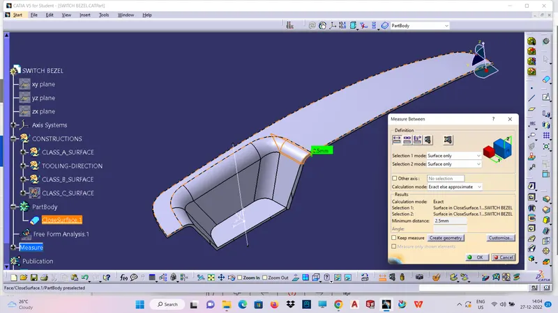
Take the Thickness of the component to be 2.5 mm
REPORT:
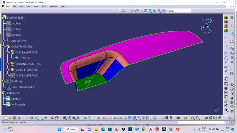
Given class A sufrace:
STEPS:
- Check the connectivity of the Class A Surface .Ensure that there is no gap between the component, using join command check it or by clicking boundary command.
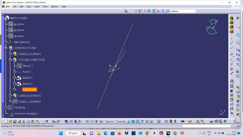
- Find the possible tooling direction for the given component,it is the direction of mould(core or cavity) opening and closing.
- NEXT FIND THE DRAFT ANALYSIS,DRAFT IS required on all the parts in the direction of mould movement in order to allow parts to release (or) eject from the molds properly
- DRAFT NOMINAL VALUE:3 degree is the nominal value,7 degree for textured faces
- colour ranges in draft vanalysis
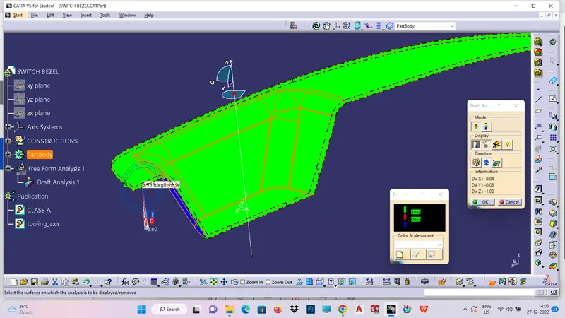
green-draft above 3 degree
red-below 0 degree
blue-0 to 3 degree
Draft is providing angles or tapers on the product engineering features such as ribs,screw bosses,that lie parallel to the direction of release from the mould eases part ejection.
The draft is done based on the tooling direction
THE ORANGE COLOUR BISECTING LINE IS THE MAIN TOOLING AXIS:
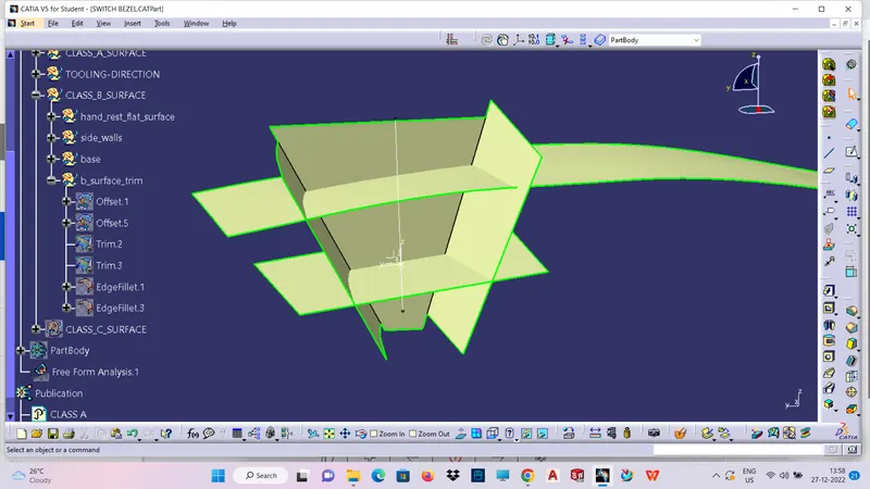
CREATION OF CLASS B SURFACE:
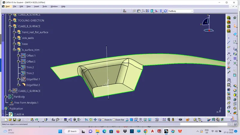
CREATION OF CLASS C SURFACE:
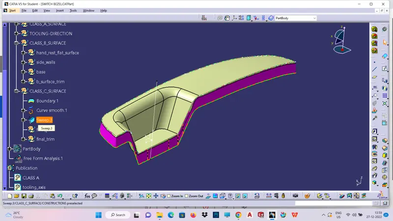
THIS VIEW SHOWS CLASS_A_B_C SURFACE:
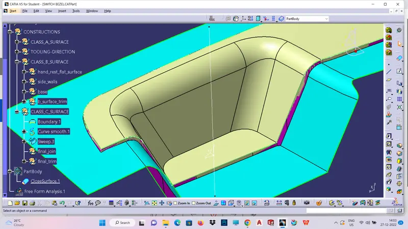
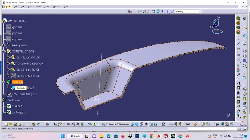
CLOSURE PART BODY OF SWITCH BEZEL:
SHOWS THE THICKNESS OF SWITCH BEZEL IS 2.5
DRAFT ANALYSIS OF SWITCH BEZEL:
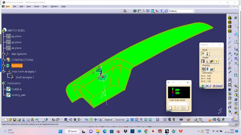
ANALYSIS UNDER THE RESULTING AT A POINT IS APPROXIMATELY AS6.555
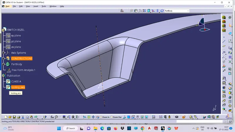
CONCLUSION:
Thus the switch bezel is designed ap per design guuidelines by using given class A surface
and it also satifies and pass the draft analysis.