Week 8 - Challenge 2 - Switch Bezel Design
AIM:
To create the Switch bezel component through the given Class A surface and at the end of the performing the draft analysis on the model.
OBJECTIVE:
To model a Switch bezel and perform draft analysis on the model.
TOOLING AXIS:
Tooling axis defines the mold or core and cavity opening direction. we should create a tooling axis in such a way so that it should cover most of features, holes, geometries and most of the crosssectional area. Here we using Bisecting method to find out tooling direction. we can use any method but the ultimate is to reduce the cost of manufacturing by reducing the complicity in manufacturing the component.
DRAFT ANALYSIS:
Draft Analysis is a method of checking the draft angle on various faces of a part with a particular direction. The draft Analysis command enables you to detect if the part you drafted will be easily removed. Draft analysis helps to detect if your drafted part is easily removable from the mold or die. All plastic components will have a minimum draft of 0.5 to 3 deg.
PROCEDURE:
Creating the Tooling Axis.
- First import the Class a Surface of switch bezel model in CATIA V5.
- Check the connectivity of class A Surface Using Boundary Options.
- Visually check which direction is better for creating tooling axis.
- First Create a dummy Tooling Axis in Z direction.
- Now Using the intersect option, select the YZ plane as first element and base bracket as second Element.
- Now create lines through the walls of a base bracket using point option with the help of intersect 1 where you think the tooling might create problem
- Now using these 2 lines create a bisecting line from reference point in Z direction. This will form a main Tooling Axis in Z direction.
Performing the draft analysis.
- Open Draft Analysis option form Insert>Analysis>Feature draft analysis.
- A new window pops by default it will be in quick analysis mode. Change the range to 2.9 deg.
- Next Position the compass on the tooling axis by dragging the compass from the top right corner of the working area. W axis of the axis system lie on the Tooling Axis.
- Then define the compass by click on the compass icon on the draft analysis window. Then lock the position of the compass by clicking the lock icon.
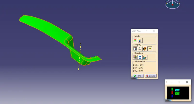
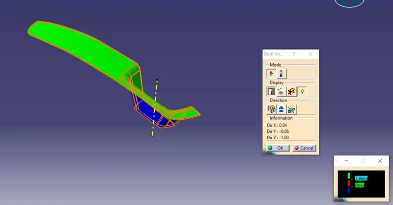
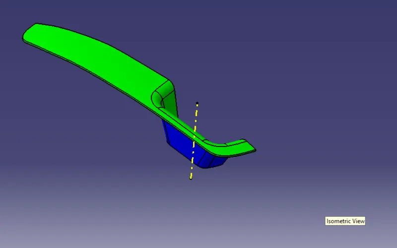
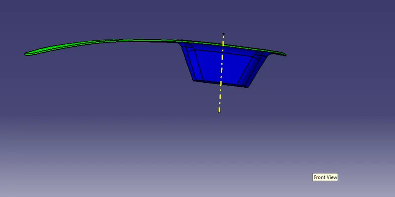
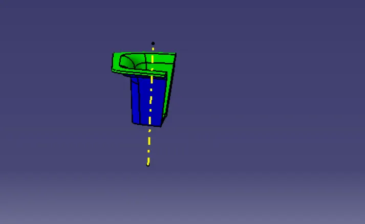
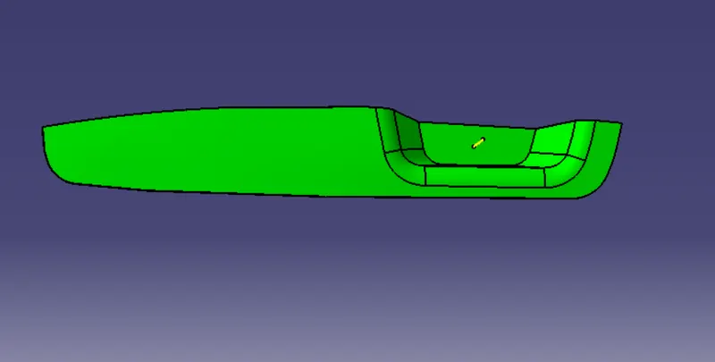
- After that select the surface and the whole surface will show a color range. If it Shows the surface in fully green, which means all faces are having a minium draft angle and its good for manufacturing.If any face is showing blue or red color we have to work on that face to give a good draft.
Result for draft analysis:
Class A surface
Final plastic component
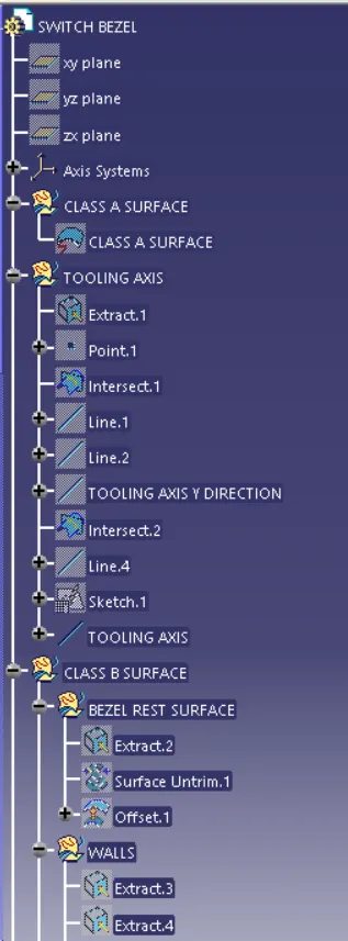
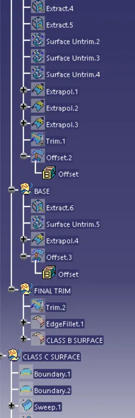
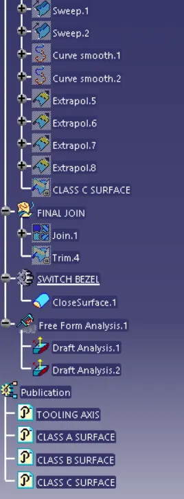
FEATURE TREE:
ORIENTATIONS:
CONCLUSION:
Swith bezel plastic component using class A Surface have been Successfully created and draft analysis also been performed for the same.