Radar Mast & Final Assembly of Yacht
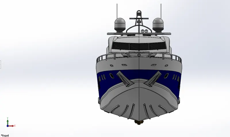
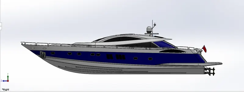
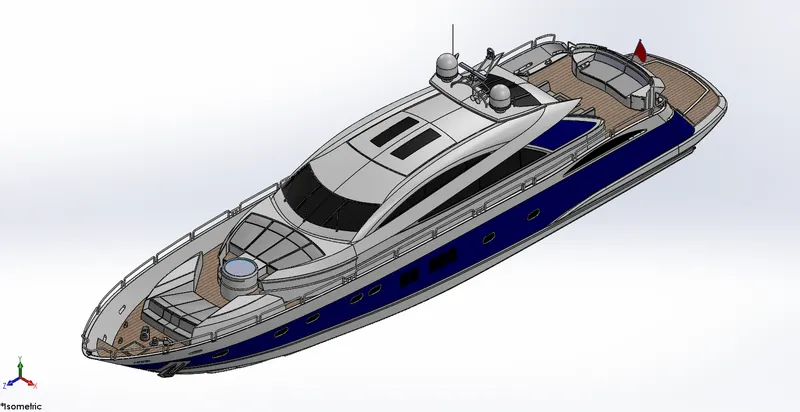
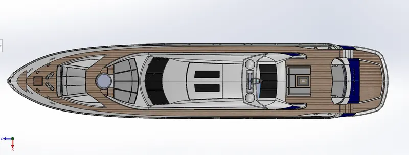
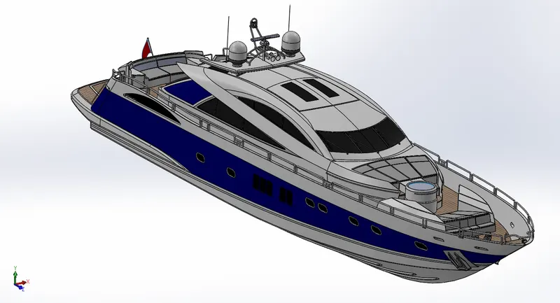
MODELING, ASSEMBLY AND PHOTO REALISTIC RENDERING OF YACHT
1) OBJECTIVE
- To design the individual parts of Yacht with required dimensions in SOLIDWORKS.
- To carryout assembly of designed parts using suitable relations of all part models in SOLIDWORKS.
- To add Decals, Lights, Camera, Appearance and start rendering the assembled model.
- Apply Photoview 360 and SOLIDWORKS Visualize rendering tools, and obtain realistic view of the model.
2) INTRODUCTION
SOLIDWORKS is a CAD modeling software which is used for solid and surface designing various parts. Here with the help of commands we draw the sketches of individual parts of yacht using the given dimensions. Convert those 2D sketches to 3D model in solidworks. After designing all individual parts we carryout assembly of the yacht. Next step is to add decals, lights, camera and do rendering in solidworks. To get the realistic view of the designed model we use Photoview 360 and SOLIDWORKS Visualize rendering tools. Here we add suitable environment, backplates, appearance and set the image quality for getting realistic view.
The various parts of Yacht are as follows:
- Propeller
- Radar
- Hull
- Garage Door
- Rear Seat
- Front Seat
- Middle Seat
- Superstructure
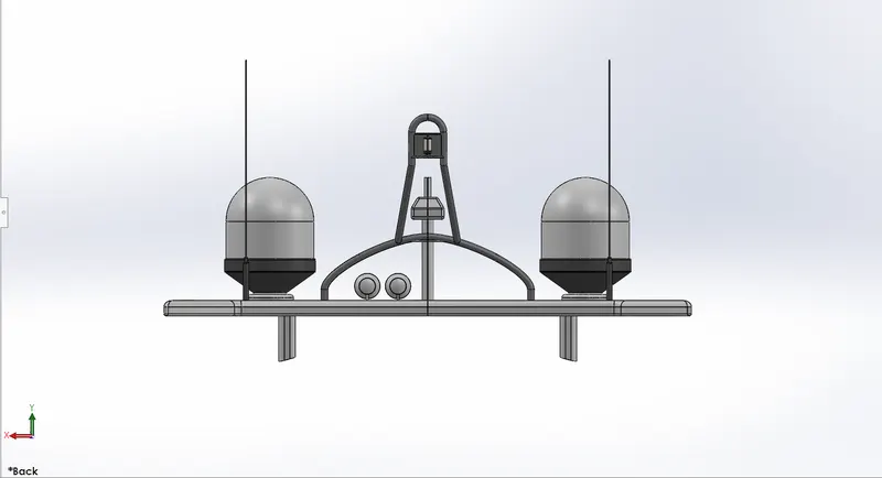
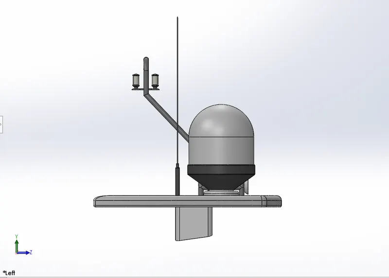
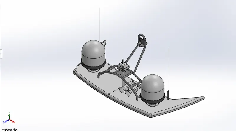
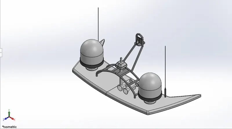
- Radar Mast
3) DESIGN METHODOLOGY
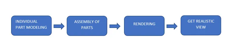
In this project we used bottom-up approach : First we design the individual components and then assemble all the components to make a complete product.
4) FEATURES
Let us discuss the features which are used while designing the individual components of Yacht.
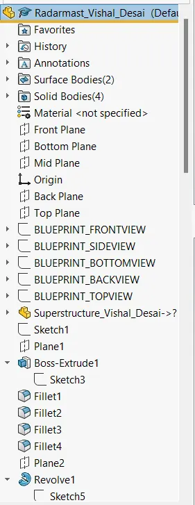
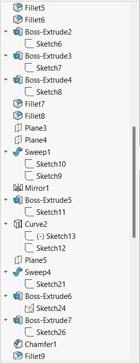
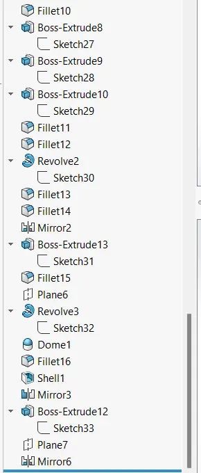
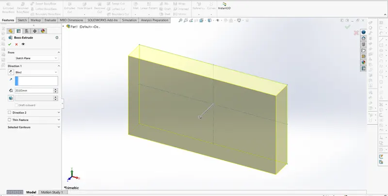
Extruded Boss
It is the basic feature in SOLIDWORKS. To use this feature, first we need to do a fully defined 2D sketch and
then convert the 2D sketch into a solid body. After choosing the extruded boss option a property manager
window pops-up. Here we add dimensions in the required directions and also we need to choose the start
and end point of the feature. Blind, midplane, from the vertex are some of the available options to use.
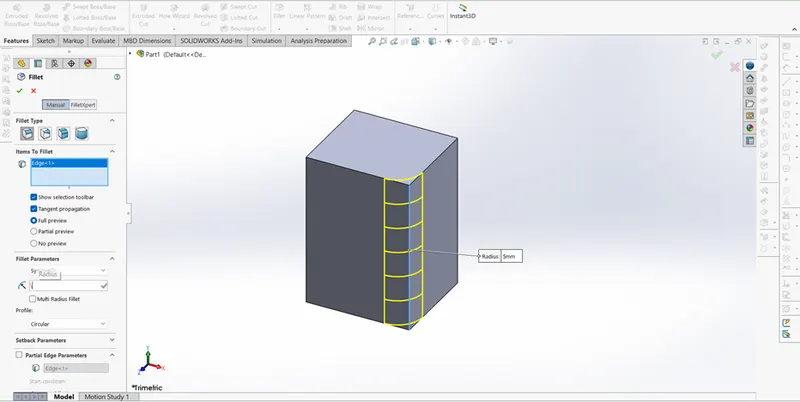
Fillet
Some of the 3D shapes have sharp edges which need to be given smoothness. For this purpose we add fillets.
By using this feature the edges get some roundness with appropriate radius. By this we can delete the unwanted
material from the solid body and give it a nice appearance. Constant size, variable size, face and full round fillets
are the types of fillets used.
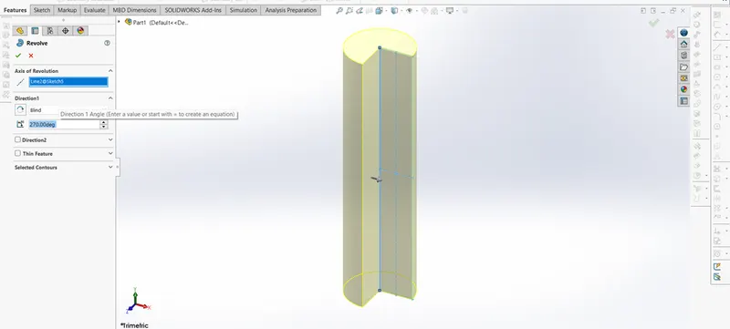
Revolved Boss
It is used to create solid 3D model around an axis. The sketch can be revolved around an axis to add materials
to it. Hollow cylinders, hollow spheres, solid spheres can be created using this feature. We need to select the
axis of rotation and give it a direction to come into existence.
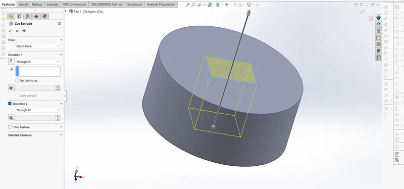
Extrude Cut
Extrude cut feature removes materials from the part. We can use this tool by projecting a sketched section
Normal to the sketching plane. Both open and closed sections can be used to create a cut. Removing material
using a closed section creates a slot.
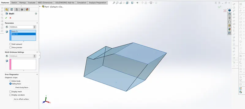
Shell
The shell feature hollows out a part, leaves open faces which are selected, and creates thin walled features on
the remaining faces. To create a closed, hollow model we need to simply do not select any face on the model.
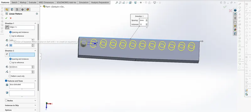
Linear and circular pattern
Linear patterns are used to create multiple instances of one or more featues that can be spaced uniformly along
one or two linear paths.
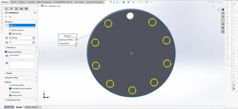
Circular patterns are used to create multiple instances of one or more features that can be spaced uniformly
around an axis.
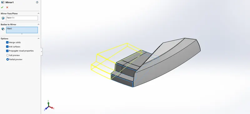
Mirror
Creates a copy of a feature mirrored about a face or a plane. Select the feature or the faces that comprise the
feature. Bodies to mirror. Select a body in a single model or multibody part to create a mirror entity. This gives
a symmetrical part without really drawing a sketch of it.
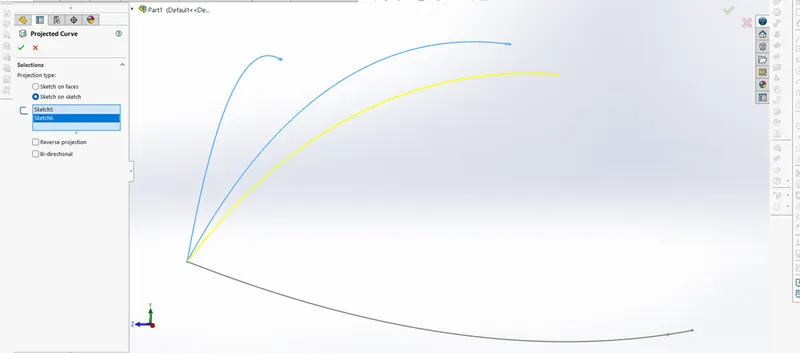
Projected Curve
The project curve feature is to create a 3D curve. We can create multiple closed or open contour projected curves
from a single sketch. Create two 2D curves using spline tool on different planes and the project a 3D curve.
The resulting yellow color curve is the projected ones.
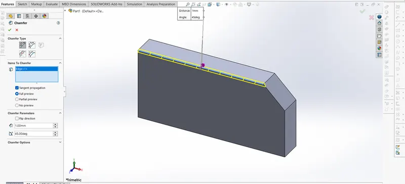
Chamfer
The chamfer tool creates a beveled feature on the selected edges, faces, or a vertex. Angle-distance, Distance-
Distance, Vertex, Offset-face and face-face are the types of chamfers.
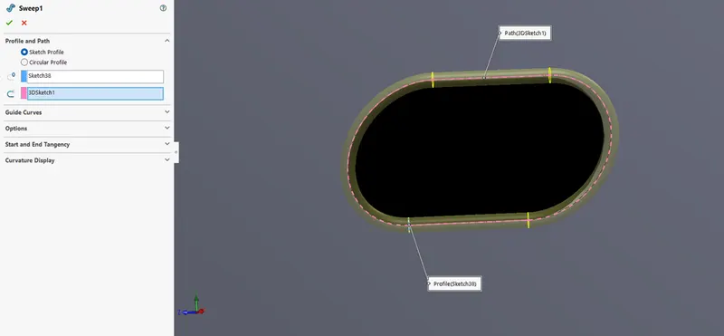
Sweep
This feature helps sweep a closed profile along a closed or open path.
Mate
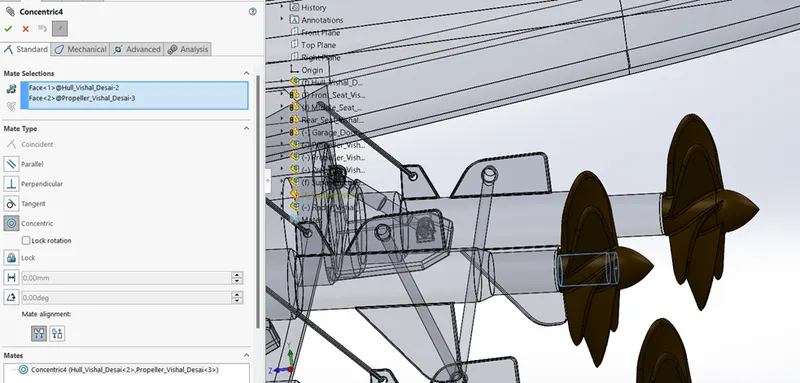
Mate creates geometric relationship between assembly and component. When we add mates, it defines the
allowable direction of linear or rotational motion of component within its degree of freedom, visualizing the
assembly’s behaviour.
The feature includes:
- Coincident mate
- Concentric mate
- Tangent
- Angular mate
Offset
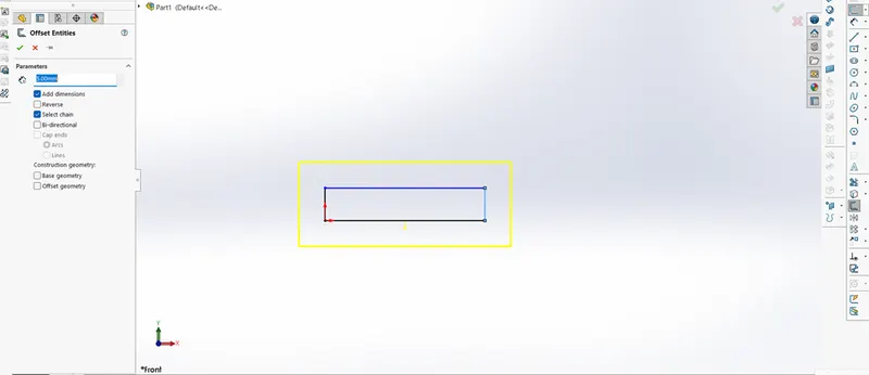
Creates concentric circles, parallel lines, and parallel curves. We can offset an object at a specified distance or through a point.
Offset entities takes a copy of an existing geometry and copies it at an offset.
Spiral/Helix
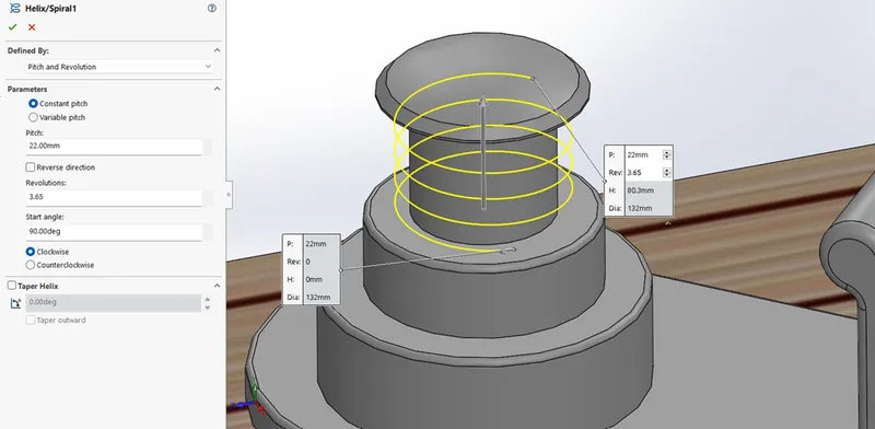
Spiral curve is used as guide curve for sweep feature.
It can be of constant pitch or variable pitch.
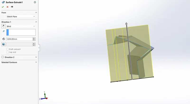
Surface Extrude
After drawing a fully defined 2-D sketch, in reference with that sketch we can extrude surfaces to surrounding features in both the directions.
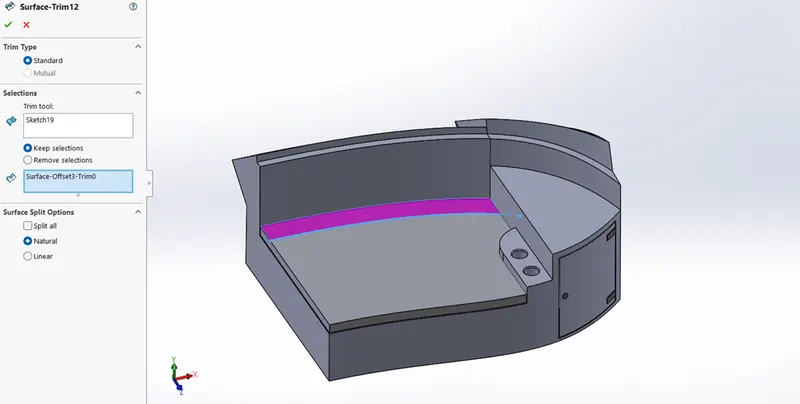
Surface Trim
Using a plane or a sketch (2-D, 3-D) as a trim tool we can trim the unwanted surfaces.
We can also keep the surfaces to be considered by this feature.
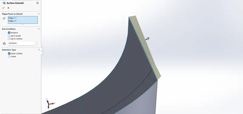
Surface Extend
We can extend any surface by selecting an edge or a face.
In this feature edges or faces can be extended upto certain distance, upto any point or upto any surface.
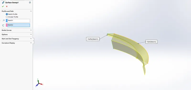
Surface Sweep
By selecting any face, edge or a curve as sweep profiles. Profile may be open or closed for this feature.
Selecting any sketch as a path we can create surface sweep. The start point of the path must lie on the plane of the profile.
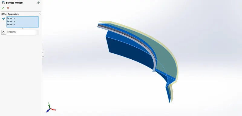
Surface Offset
This is the advanced feature to offset the entities. Just selecting surface offset and choosing the faces
as parameters we can create offset sketch of surfaces.
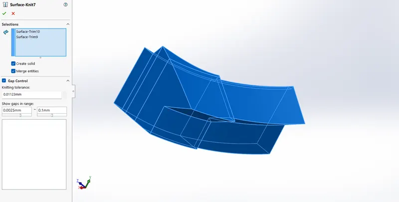
Surface Knit
This tool is to combine two or more surfaces into single entity. With this feature we can convert two or more
entities into single entity and make it a solid part. Here knitting tolerance can also be altered to control the
gaps between the entities.
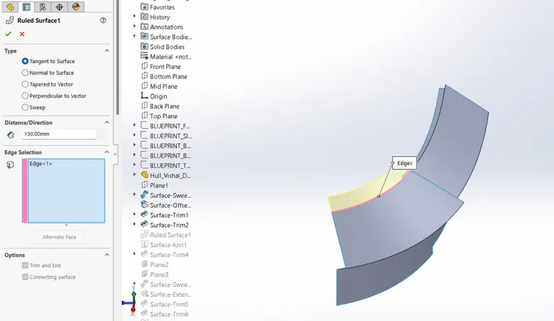
Ruled Surface
Using this feature we can create surface which extends to specified direction.
It may be of tangent to surface, normal to surface, tapered to vector and so on.
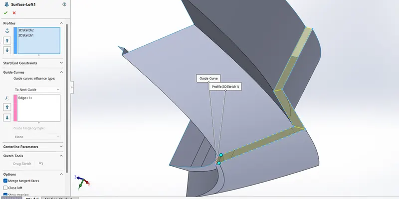
Surface Loft
Surface loft helps to create complex geometry in a single feature. It creates surface between cross-sections of the model. Faces, edges,sketches can be considered as loft profiles.
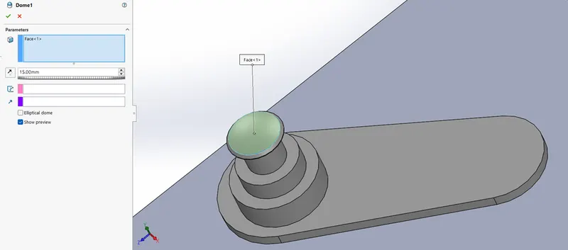
Dome
This feature helps to create a bulged surface at the end of any portion. Eliptical dome can also be applied.
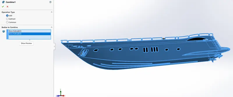
Combine
This feature helps to combine two or more parts of a model to form a single entity.
There are three types in it add, subtract and common. One can add or subtract bodies, or keep material
That is common to the selected bodies.
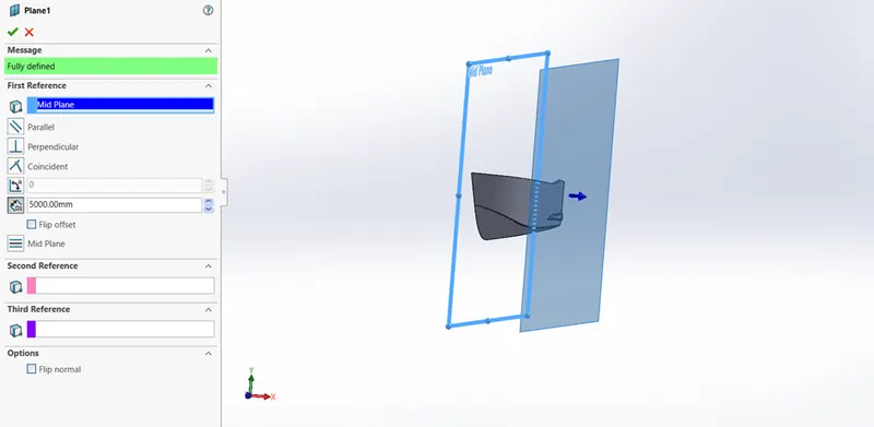
Reference Plane
It includes edges, planes, axes, points to create a plane. Using this reference plane we can create sketches
That are used in lofts, sweeps, patterns etc.
5) MODELING PARTS
Following are the parts of YACHT :
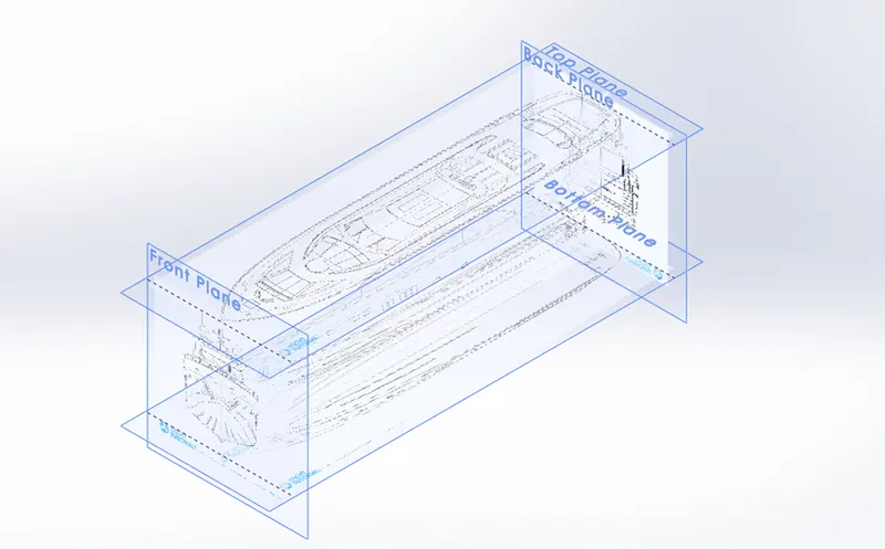
Blueprint Setup
The first step in modeling the yacht is to setup the blueprint. For this go to tools, sketch tools and sketch picture.
Browse the picture that is to be adjusted in particular plane. By this applying all views picture on appropriate
planes we get blueprint setup to proceed further.
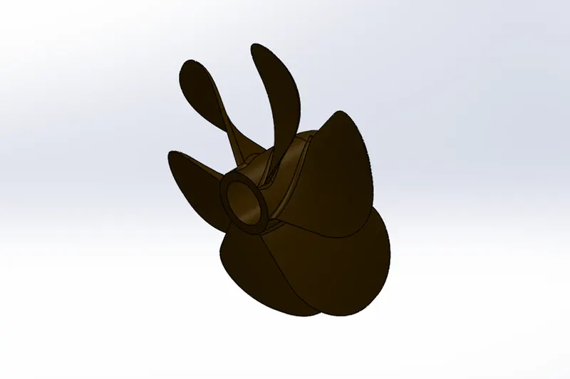
Propeller
It is a mechanical device for propelling a boat, consisting of a revolving shaft with two or more broad, angled
blades attached to it.
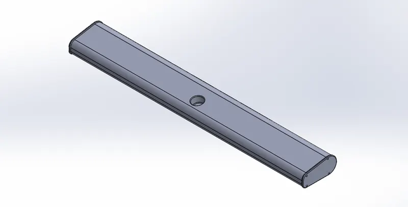
Radar
It is located at the top of the model to detect the presence, direction and objects by sending out pulses of radio waves which are reflected off the object back to the source.
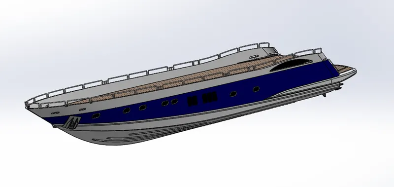
Hull
The main body of a yacht including the bottom, sides, and deck but not the masts, superstructure, engines and other fittings. It acts like protective portion for goods, machinery from natural calamity.
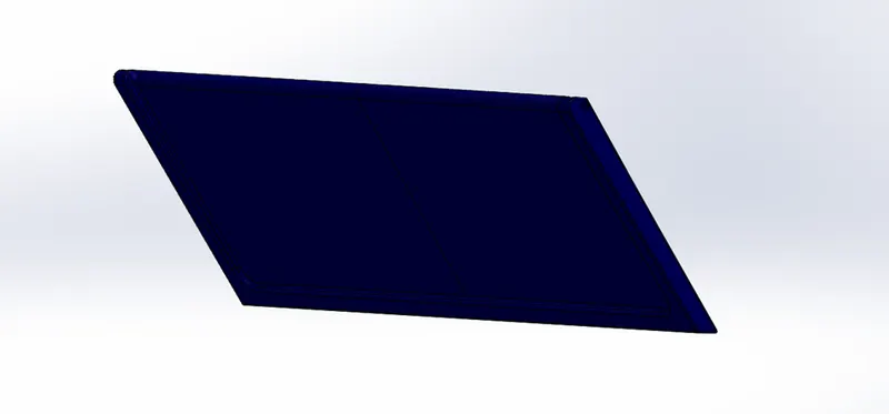
Garage Door
Garage door is located at the back portion of the model used to protect the vehicles parked in the garage.
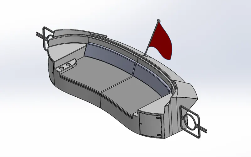
Rear Seat
It is located at the rear side of the yacht.
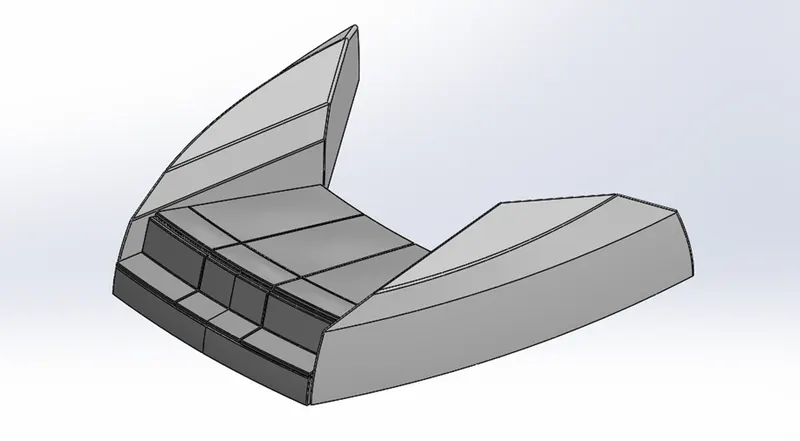
Front Seat
Front seat is located at the front part of the model. It is basically mounted at the front of the superstructure.
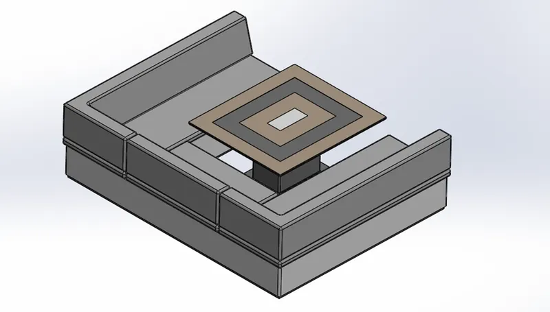
Middle Seat
Middle seat is located at the middle portion of the model.
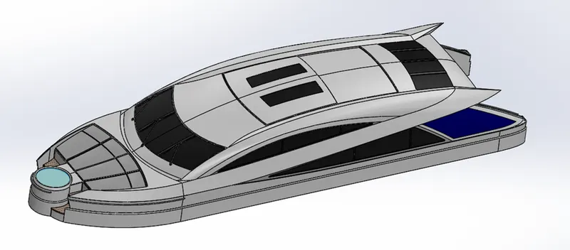
Superstructure
It is the part which consists navigation controls, front seat and pool. It is mounted at the top surface of the hull to give the model a proper shape of a yacht.
Radar Mast
This is an electronic navigation instrument which uses a rotating antenna to sweep a narrow beam of microwaves around the water surface surrounding the yacht.
6) ASSEMBLY
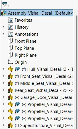
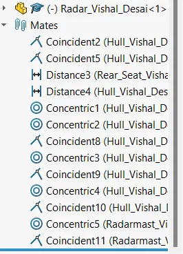
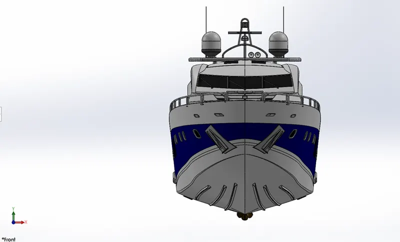
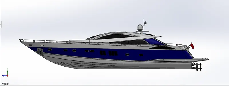
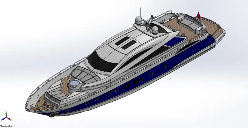
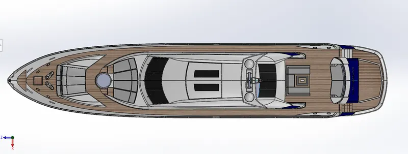
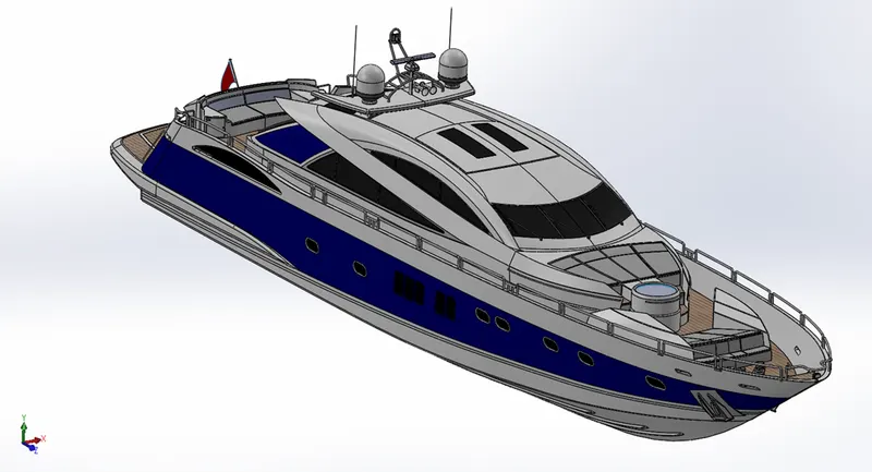
- Now that we have designed all the individual components of the Yacht , we need to assemble them by creating a new assembly file, importing all the parts which are fully modelled.
- In assembly, mate feature is most commonly used to locate and relate the parts with one another.
- Standard mates include angle, coincident, concentric, distance, lock, parallel, perpendicular and tangent mates. Advance mates include limit, linear, path and width mates.
- Hull is the main component which is inserted first. The other components are inserted one by one. By using planes for reference and giving the mate feature once the part gets fixed it floats with the main frame.
- Some parts need to be modified during assembly to make it look accurate.
7) PHOTO REALISTIC RENDERING
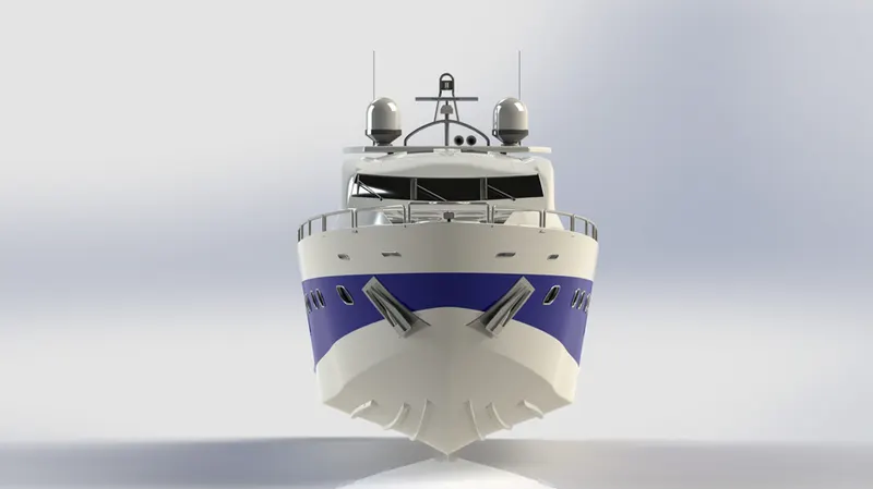
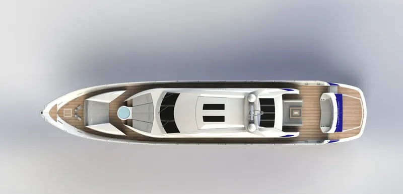
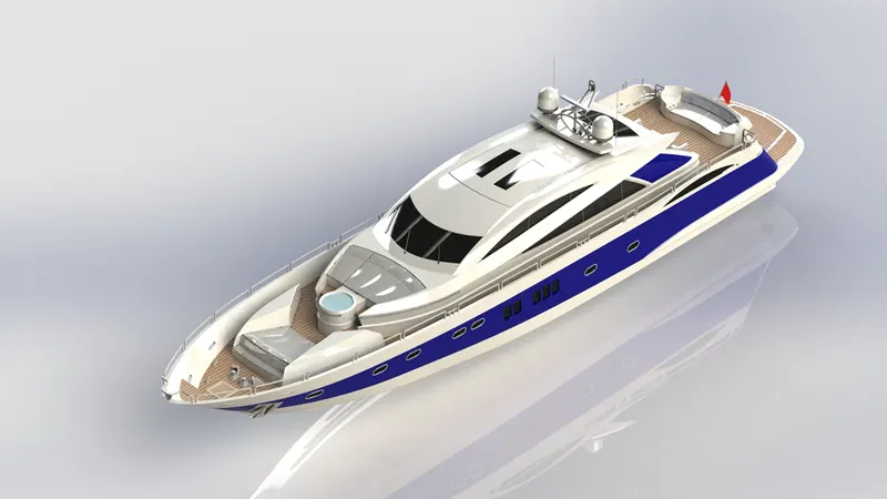
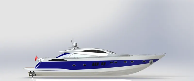
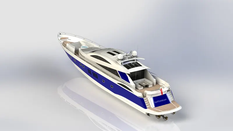
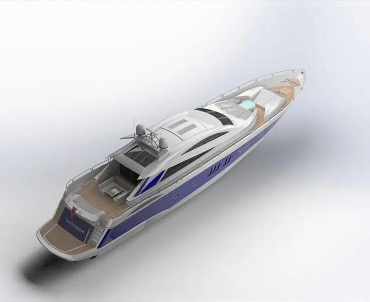
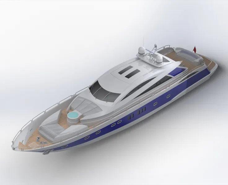
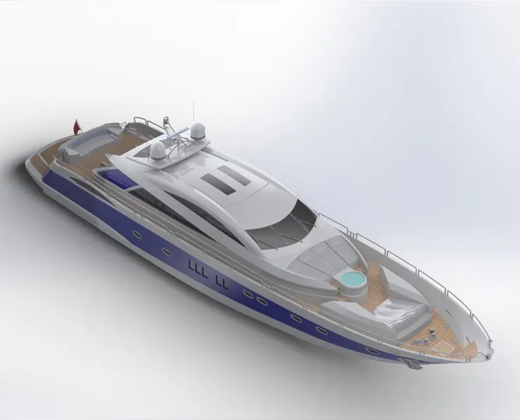
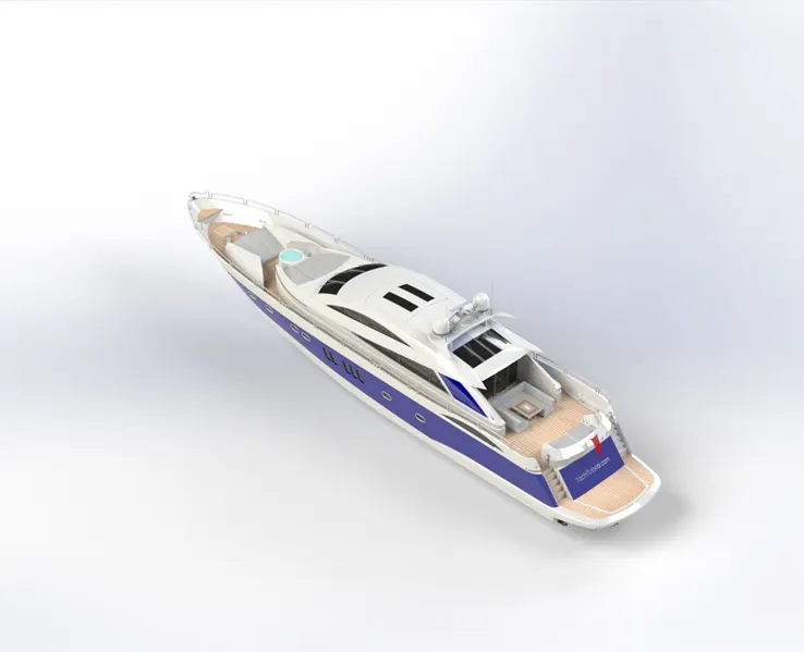
- In this project we use Photoview 360 and SOLIDWORKS Visualize rendering tools, and obtain realistic view of the model.
- PhotoView 360 is a SOLIDWORKS add-in that produces photo-realistic renderings of SOLIDWORKS models. The rendered image incorporates the appearances, lighting, scene, and decals included with the model.
- SOLIDWORKS Visualize is the fastest and easiest way to produce photo quality images by bringing in the YACHT model. It generates photo quality image, interactive animations, and 360 degree spin to effectively communicate the most complex design details.
- In this we can set scenes, backplates, environment, lights and cameras to get the realistic view and obtain the rendered images.
8) CONCLUSION
- All the individual parts of yacht are modelled and assembled using SOLIDWORKS.
- The assembled model is rendered and with the help of PHOTOVIEW 360 and SOLIDWORKS Visualize realistic views of Yacht are obtained.