Advanced Sheet Metal Design Using NX Cad Challenge_2_Box Assembly
BOX ASSEMBLY
OBJECTIVE
To design a sheet metal Box Assembly and carryout drafting using Siemens NX.
INTRODUCTION
- NX, formerly known as “unigraphics”, is an advanced high-end CAD/CAM/CAE, which has been owned since 2007 by Siemens PLM Software.
- Sheet Metal Fabrication is the process of forming parts from a metal sheet by punching, cutting, stamping, and bending.
- The thickness of sheet metal starts from 5 mmand goes up to 6 mm. Anything above that is a metal plate. The thin sheet metal is easy to form, while still providing great strength.
- Drafting is one of the application in NX Sheet Metal used to get 2-D drawings of all the different views of the designed model.
DESIGN METHODOLOGY

DESCRIPTION
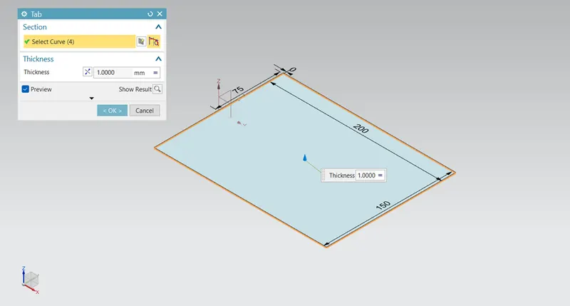
1. Tab - It is used to create a base part by drawing a sketch with required thickness.
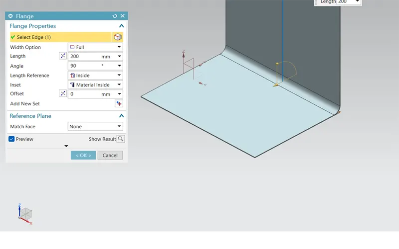
2. Flange – Flange is created using any edge as a reference. Variable length and angle flanges can be created.
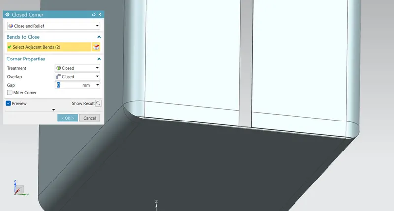
3. Closed corner – This feature is used to close a corner where two adjacent flanges meet. This is done by extending both the flanges.
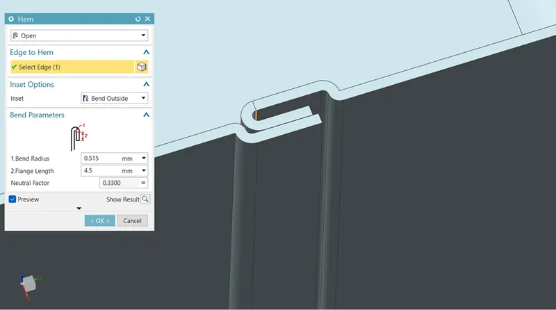
4. Hem flange – This feature is used to fold any edge of the flange. This is done to increase the stiffness of the model.
5. Mirror body – After creating half part of the box model, using the mirror body feature it is then mirrored with reference to suitable plane, to get a closed walled model.
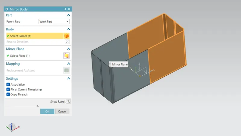
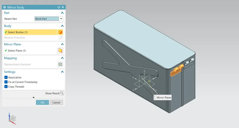
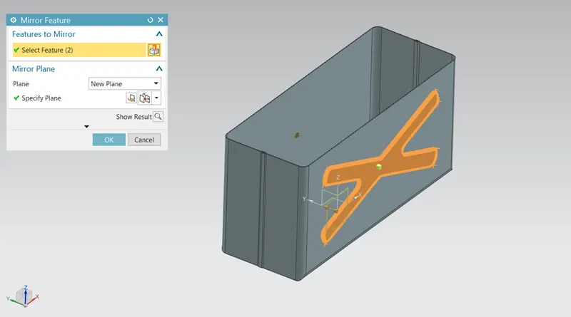
6. Mirror feature – This is used to mirror any feature to the other side of the body with reference to suitable plane.
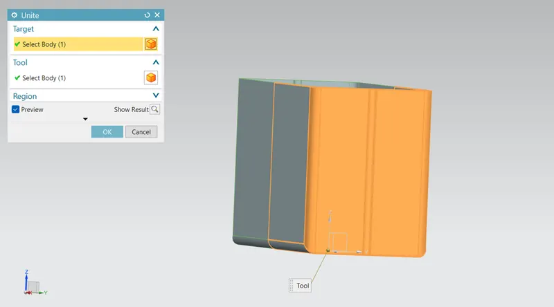
7. Unite – This feature is used to unite/combine two bodies to make them a single body.
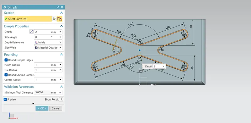
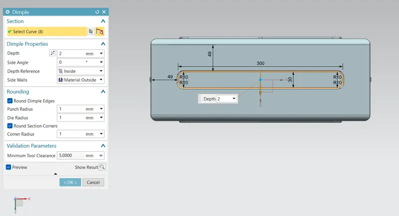
8. Dimple - It is used to lift a portion of model inside or outside by creating a sketch. Basically is is also used to add design or logos.
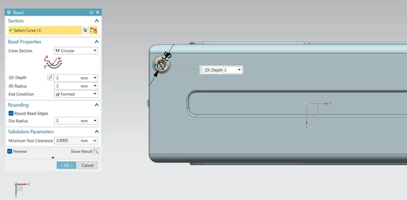
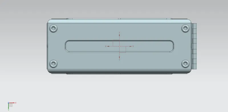
9. Beads - This feature is used to stamp into the sheet metal taking any sketch as a reference to increase the stiffness.
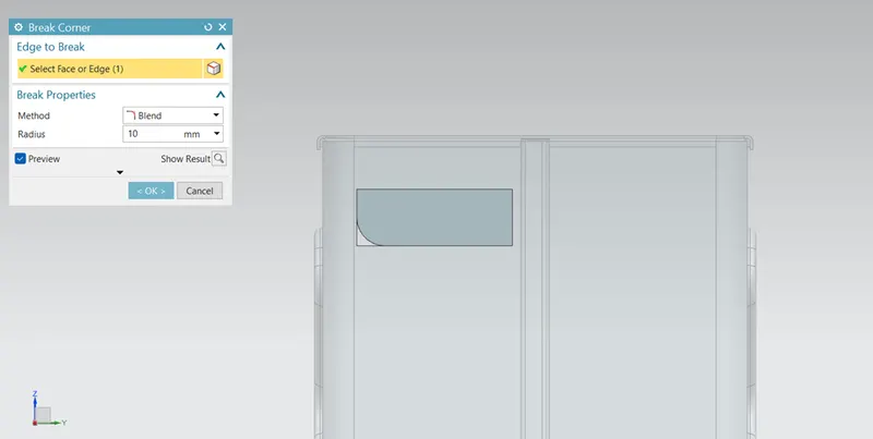
10. Break corner – This feature is used to create a chamfer at the sharp edges in the sheet metal model.
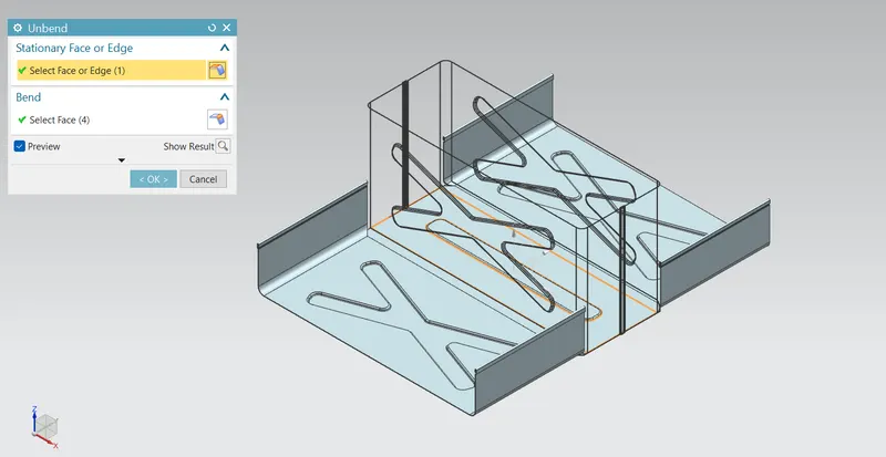
11. Unbend - This feature is used to unbend the bent model. This is done by selecting the central flat face which is to be stationery and select the bent face to be unbent.
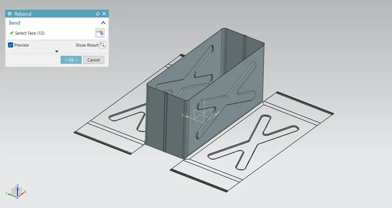
12. Rebend – This feature is to rebend the unbent model. This is done by selecting all the bends.
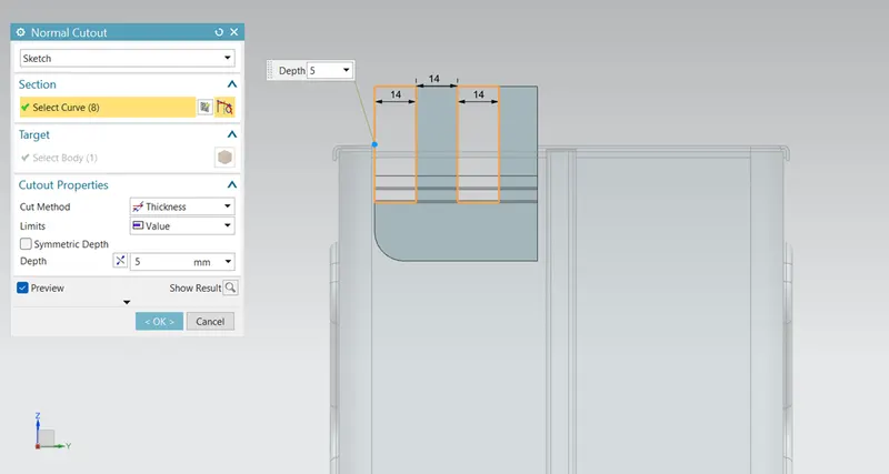
13. Normal cutout – This is used to make a cutout on the sheet metal model to remove the material by creating a sketch.
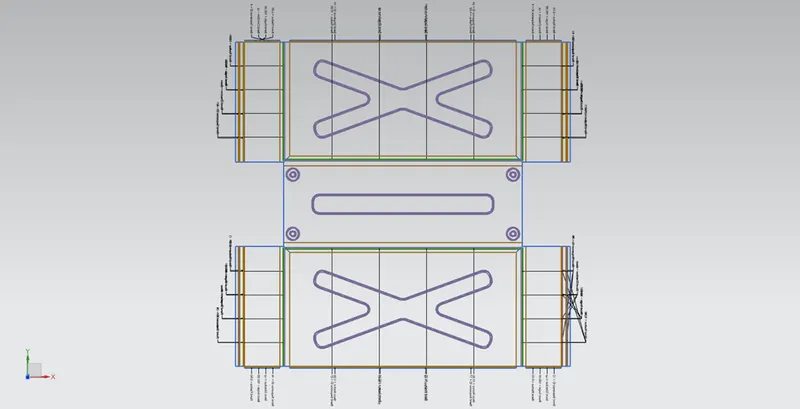
14. Flat pattern – This feature is used to obtain a 2D projection of the flat sheet metal.
VIEWS OF THE MODEL
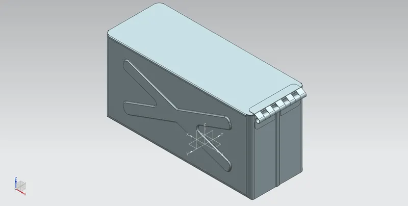
- Isometric view
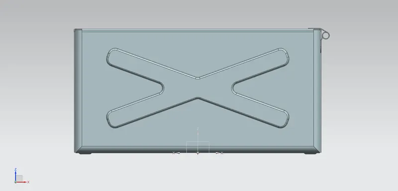
- Front view
- Side view
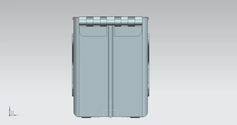
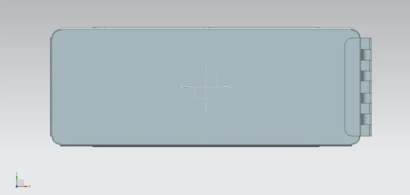
- Top view
DRAWING SHEET
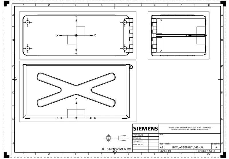
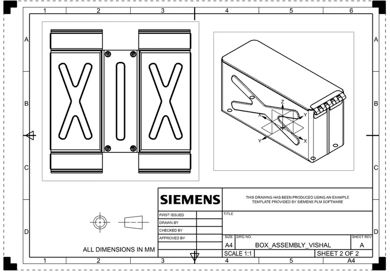
After designing the 3-D model of the box assembly, it is then made as a single sheet by using flat pattern.
Thereafter it is imported in the drafting sheet to get a 2-D drawing for clear understanding. Also all the views of the model are imported into the sheet.
CONCLUSION
- Box assembly in NX sheet metal is created by using the given sketches and procedures.
- Flat pattern of the model is obtained and drafting is done.