Week 8 - Challenge 2 - Switch Bezel Design
AIM: The aim of this project is to develop the product design of the switch bezel with the help of the class A surface following the OEM standards.
INTRODUCTION:
Class A: Class A surface is the term mainly used to automotive design industry. It describes the final production surface data for the aesthetic parts of the car.
Class B: Class B surface is the secondary surfaces which is not visible normally. These must be smooth and “error-free” as well, but not held to the standards that class A surfaces.
Class C: Class C surfaces are the backside surfaces that can have tool marks, flash and other imperfections without hurting appearance function etc.
The steps involved in creation of this project are:
- Bringing the class A surface of the switch bezel in Catia V5 software
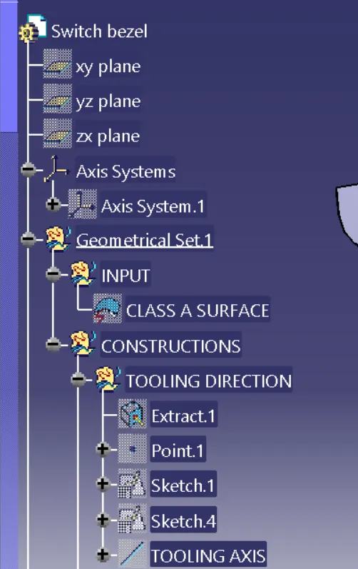
- Determining the tooling axis for the switch bezel
- Creation of class B surface
- Creation of Class C surface
- Joining all the Class A, Class B, and Class C surfaces of the switch bezel
- Building closed surface after joining all the surfaces
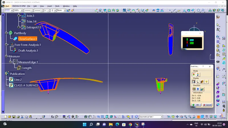
- Draft analysis on the switch bezel.
PROCEDURE:
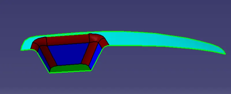
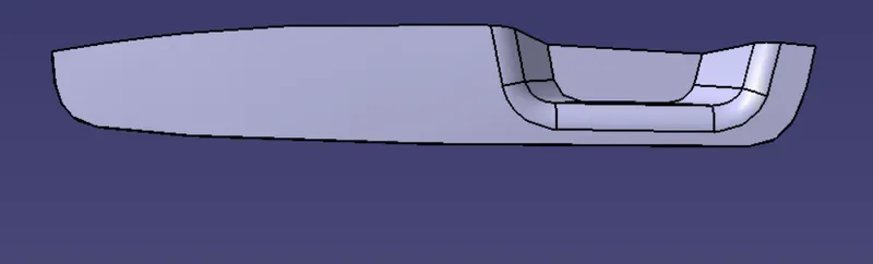
Below is the class A surface which was incorporated in the Catia V5 workbench to open.
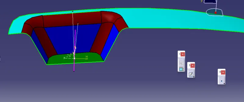
Determination of tooling axis for the above class A surface
Tooling axis: The definition tab on the tool axis dialog controls how you want the tool to orient itself whilst cutting a multi axis tool path. Tool axis – select to define the tool orientation. The default value is vertical which is used for standard 3-axis machining. However, it can also be a fixed angle or a continuously changing orientation.
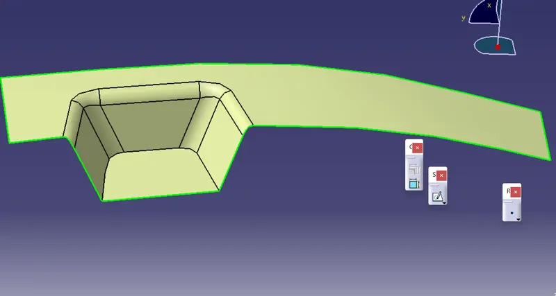
Creation of Class B Surface:
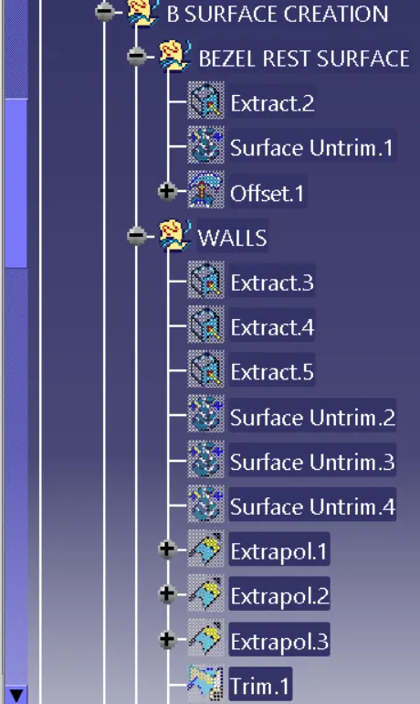
- The class B surface is created by extracting each surface of class A surface and then un trimming them.
- After the an offset of 2.5mm is given in the downward direction to generate the class B surface
- The surface are then extrapolated with a certain distance in order to create cross section among the surfaces to perform trim operation.
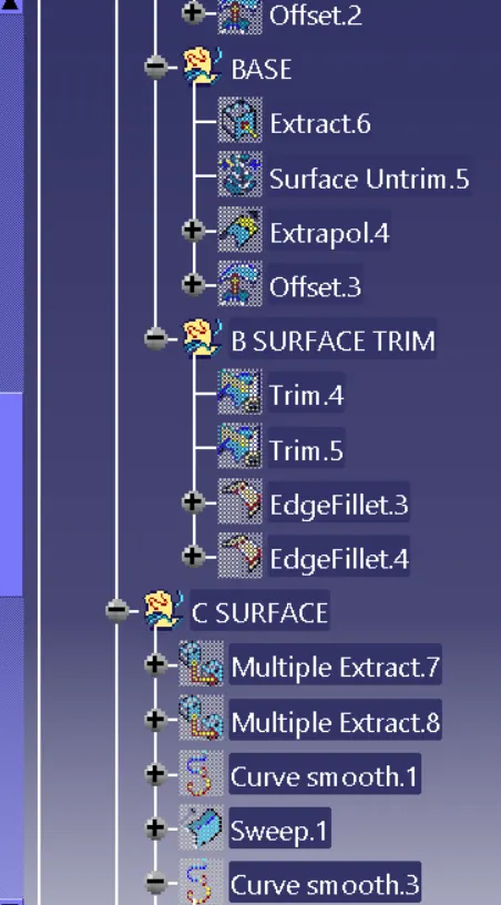
Surface trim option was used to give the class B surface required shape.
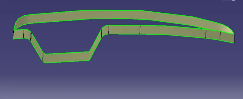
Creation of Class C Surface for switch bezel:
- For the creation of class B surface first the boundary of the class A surface is extracted using multiple extract feature
- After the sweep option is used to create the sweep along the tooling axis direction.
Class B Surface and the Class C Surface are then joined together to get desired shape
After this operation class B and class C surface are trimmed together to give the plastic product a mouldable shape.
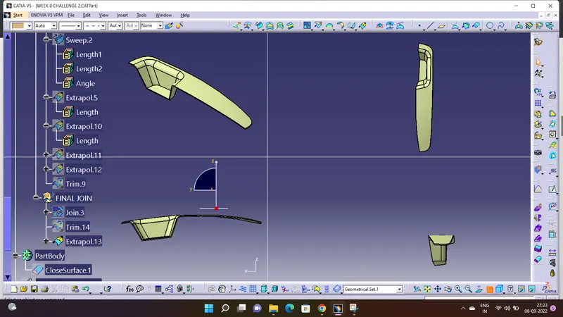
After ensuring that the surfaces formed are completely closed, the closed surface feature is used to create the solid mold of the switch bezel.
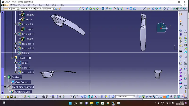
DRAFT: Drafts are defined on moulded parts to make them easier to remove from moulds.
The characteristic elements are:
Pulling direction: This direction corresponds to the reference from which the draft faces are defined.
Draft angle: This is the angle that the draft faces make with the pulling direction. This angle may be defined for each face.
Parting element: This plane, face or surface cuts the part in two and each portion is drafted according to its previously defined direction.
Neutral element: This element defines a neutral curve on which the drafted face will lie. This element will remain the same during the draft. The neutral element and parting element may be the same element.
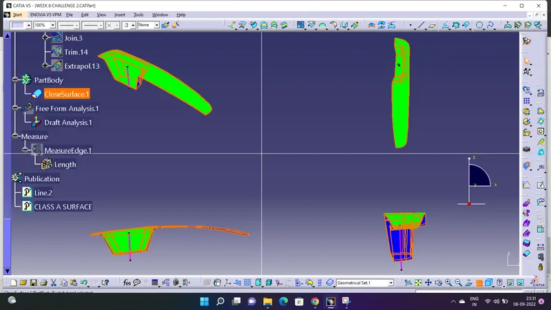
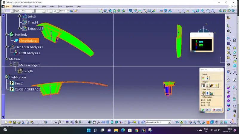
DRAFT ANALYSIS: The draft analysis command enables you to detect if the part you drafted will be easily removed. This type of analysis is performed based on colour range identifying zones on the analysed element where the deviation from the draft direction at any point, corresponds to specified values. After the draft analysis is done we can observe that the green colour shows that the drafted walls of the switch bezel are above 2.9 degrees which is a permissible criterion to manufacture in injection molding.
using 3 degrees
PART BODY VIEWS:-
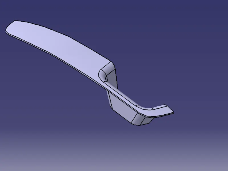
ISOMETRIC VIEW:-
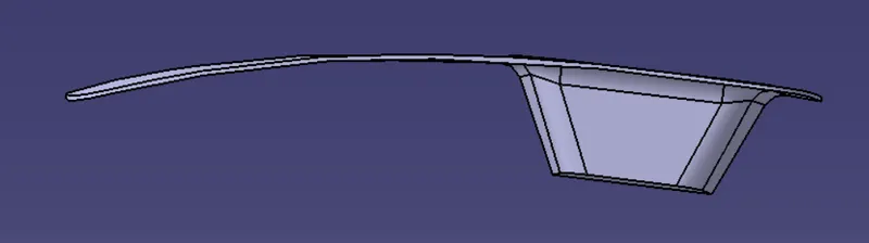
FRONT VIEW:-
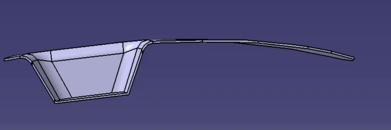
BACK VIEW:-
TOP VIEW:-
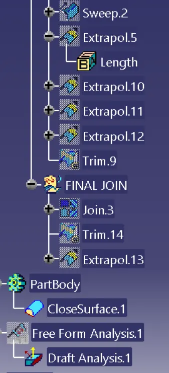
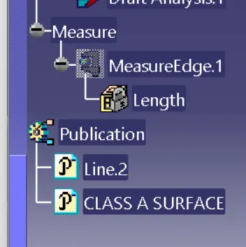
FEATURE TREE:-
Conclusion:
- Class A, Class B and Class C surfaces are created following standards of automotive industry using Catia V5 software
- Draft analysis was performed on the switch bezel and it was observed that draft was under permissible limit for the manufacturing of the component using injection moulding process.