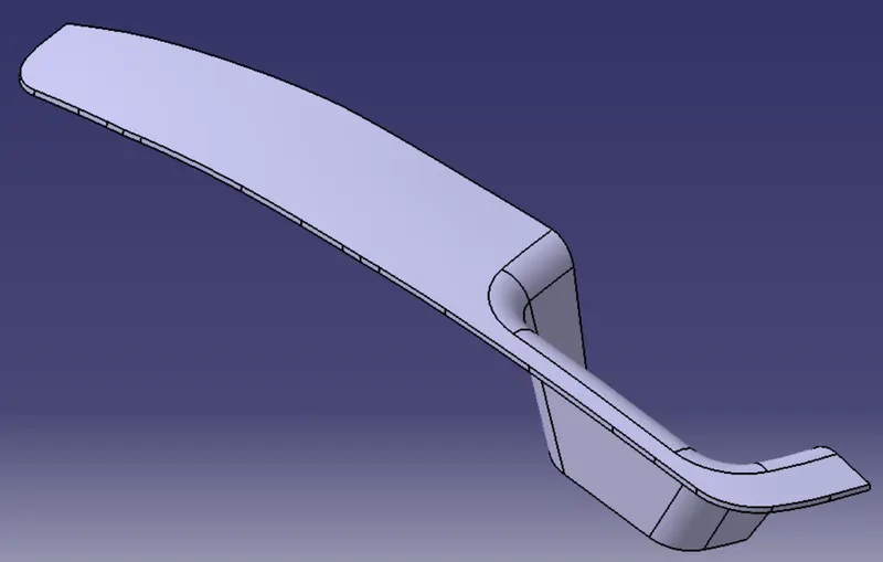
Week 8 - Challenge 2 - Switch Bezel Design
Bisecting method for Creating tool Axis
The bisecting method of crating tool axis is the process of selecting the required tooling direction. The given model or surface is inspected and a dummy tooling axis is made based on pure visual analysis and visual inspection. It is mainly based on the geometry of the model. To crate the real tool axis all the draft angle or surface with draft along the dummy tool axis is marked and a line is made in each plane perpendicular to the dummy tool axis. And these lines are bisected or drafted with minimum angle to give tool axis with respect to each plane. If there are multiple tool axis these axes again bisected to give a single tool axis.
Tool Axis Creation
- The dummy tool axis is created based on visual inspection of geometry.
- To create the main tooling axis the surface with large flat area or circle ellipse is selected, and a reference point is created.
- The intersection sketch of the surface with perpendicular planes are created. These planes are selected based on the dummy tool axis direction.
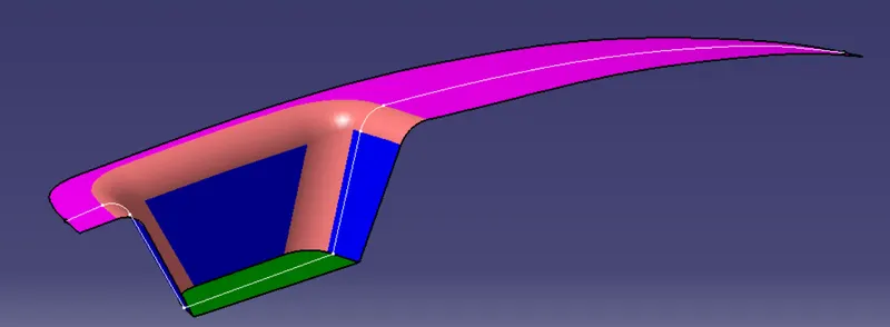
- The lines are created along the draft surface where the main draft angle expected to cause problem.
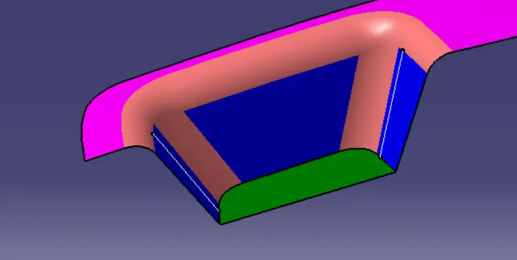
- The tool axis for each plane is created by using bisecting line or the line with minimum draft angle.
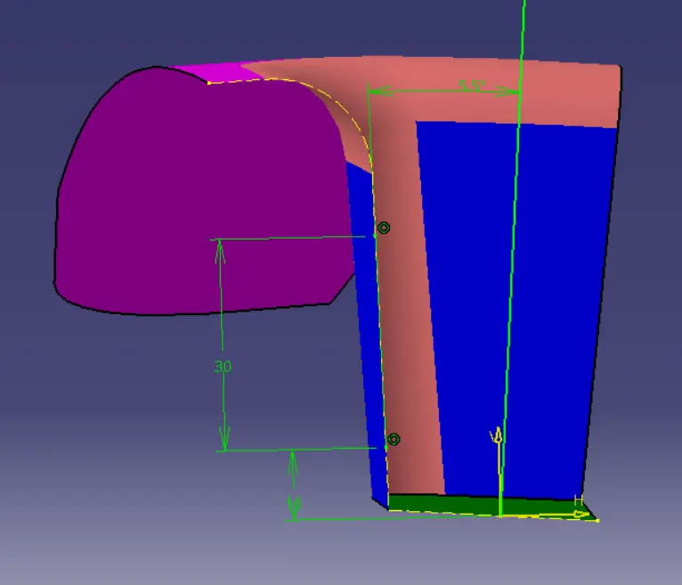
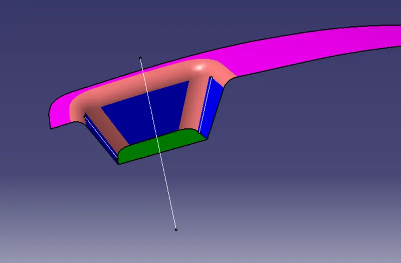
- These lines are bisected to create a final tooling axis.
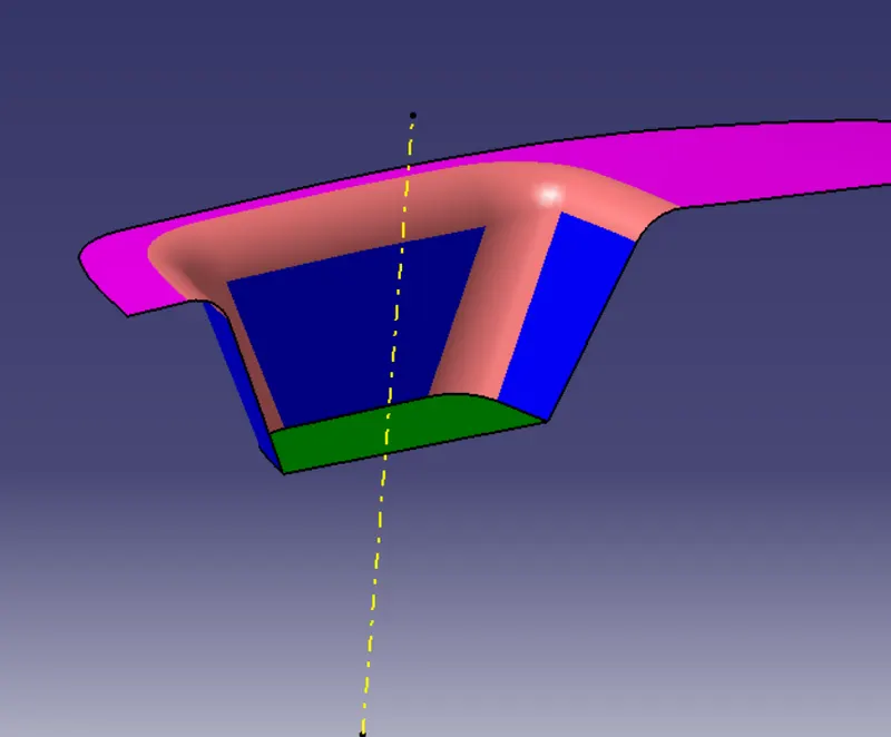
Draft Analysis
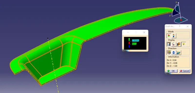
The draft analysis is conducted to make sure the ejection of the model after molding will be easy and it won’t damage the model or core.
- The material mode is selected.
- The axis is given along the defined tool axis and locked.
- The model to be inspected is selected, and the draft direction is inverted to get particular direction.
- The visual inspection is made, and is the modification needed the tooling axis is modified.
Standard Views
Front View
Side View
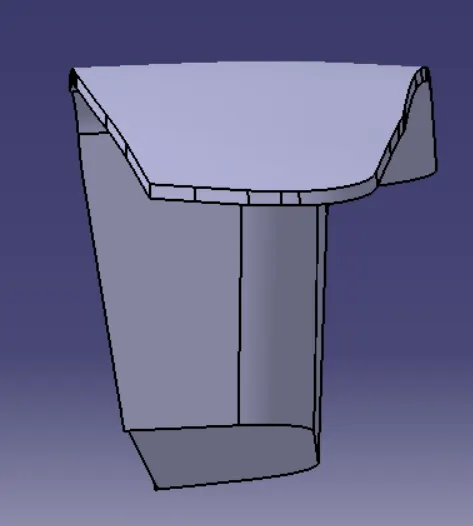
Top View
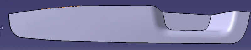
Isometric View