Week 8 - Challenge 2 - Switch Bezel Design
Week 8 - Challenge 2 - Switch Bezel Design
AIM
Create the Switch Bezel Plastic component through the given Class-A surface. To begin with, the tooling axis for the given Class-A Surface should be created meeting the requirements of the draft angle and at the end perform the Draft analysis on the model.
Take the Thickness of the component to be 2.5 mm
Requirements
- Screenshots of the Draft analysis report for both the given Class-A surface and the final plastic component
- Screenshots of the solid model with the proper color code of the draft angle in various orientations (Isometric, Front, Side, and Top View)
- CATpart should be submitted as an attachment
REPORT
Class A Surface
Class A surface is a outer styling surface on which design engineer starts designing components.
Class B Surface
This surface is created by offsetting the Class A surface. The offset value is equal to the thickness of the component. On this surafce all the engineering features are provided.
Class C Surafce
The surface joining Class A and Class B in the tooling direction is known as Class C surface.
Tooling Axis
Tooling axis is a direction in which core and cavity opens and closes. Draft angle is provided with respect to the tooling axis. While creating mold component from Class-A surface, we need to decide the tooling direction. It can be decided by visual inspection, deciding complex surfaces and bisecting method.
Tooling Axis Creation- Bisecting Method
- First check for the discontinuity of the surface received by join or boundary command. For given surface there is gap between two surfaces, so it was join by increasing merging distance to 0.002mm. Then visual observation is done to decide which direction will be more feasible to create component.
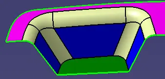
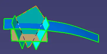
- Few surfaces are identified which can create concern over draft angle (Refer below image-Surface in Blue colour).
- A reference point is created in center of the bottom surface. And Axis system is created at that point.
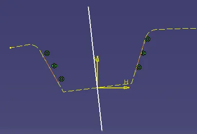
- Two different cross section profiles are formed using intersection with plane.
- For first profile in yz plane, Lines are drawn on the concerned boundary intersection profile. Then line is drawn bisectiong these two lines.
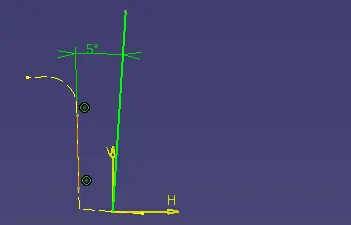
- For the second intersection profile in xz plane, there is only one surface. So A line is drawn from the center point at 5 degrees angle with the boundary line.
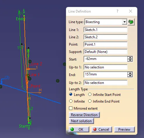
- A bisecting line is created from the two lines created earlier with intersection profile. This bisecting line refered as Tooling axis line and this method is known as Bisecting method to create tooling axis.
Draft Analysis
To reduce the risk of damage to parts and tool while ejecting from mold a draft angle is provided to walls which are parallel to the tooling direction. It assists with releasing the part from mold.
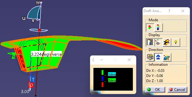
To perform Draft analysis in Catia, Draft analysis feature is used. For that First tooling Direction decided. Then make sure material view mode is used. After opening the window, align the compass with the tooling axis by dragging it on the axis. Then click on the surface or the body on which draft analysis is need to perform. In the bottom black colour window provide the minimum draft angle and then match the body color with this color scale. Green indicated draft angle is more than minimum draft angle. If it is blue then it is between 0 to minimum draft angle. And red denotes it is less than zero. By this way we can identify the areas with draft angle less than minimum draft angle and work on that area by changing tooling axis angle.
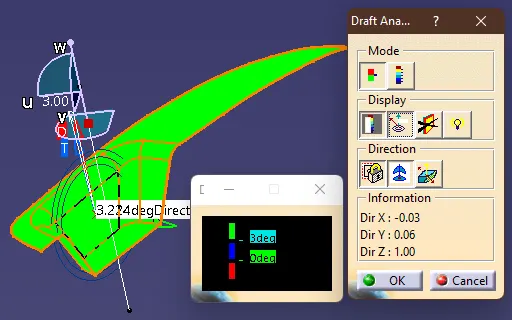
Procedure
- Check for Discontinuity. If any, join the surface.
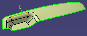
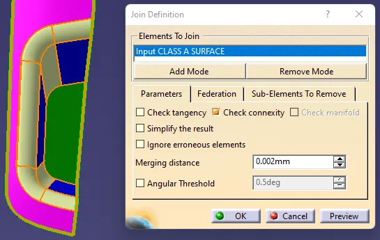
- Identify concern planes. Create line in every concern planes. From the these line create bisecting line ie. final Tooling axis.
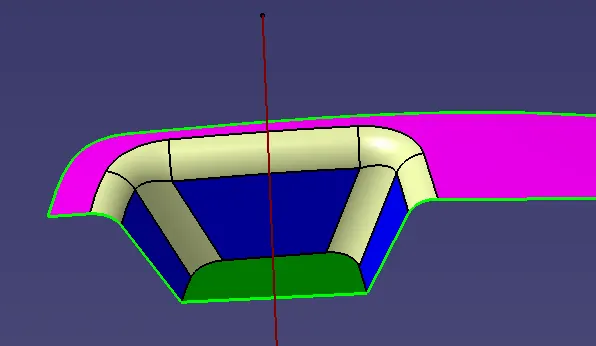
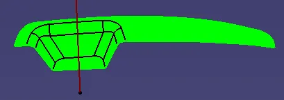
- Perform Draft analysis on Class A surface in the Tooling Direction
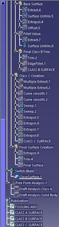
- Create Class B surface by offseting Class A surface and join them by trimming. Fillet Edges.
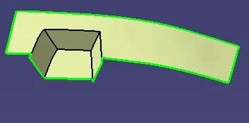
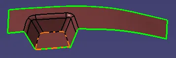
- Create Class C surface by extracting boundary of class A surface and sweep it by minimum draft angle along the tooling direction.
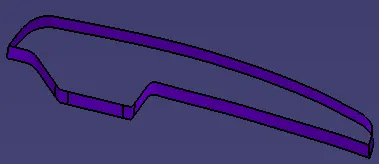
- To create final closed surface body, join and trim all three surface together
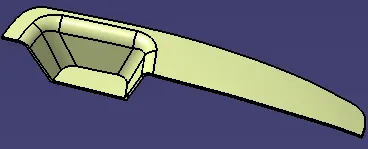
- Convert this surface body into Solid body by Close Surface Tool
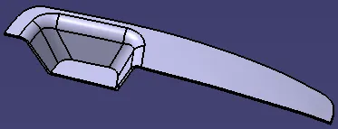
- Perform Draft analysis again on the Solid body.
RESULTS
Expanded Tree
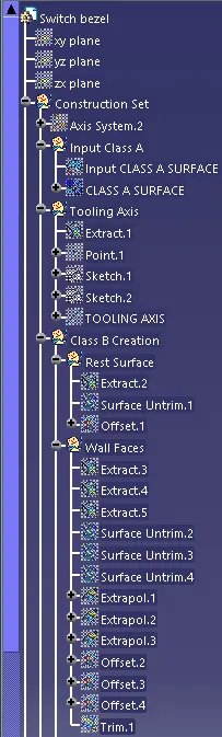
Draft Analysis
- Class A Surface
Class A surface Draft angle more than 3 degrees with respect to tooling direction. - Solid Body
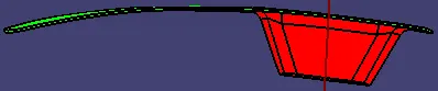
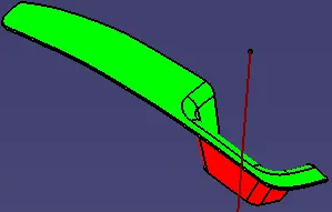
In Solid body Draft Analysis, The Top and Thickness (Class A and Class C surface of the body) shows the Draft angle more than 3 degrees. While Bottom surface (Class B) has negative draft angle.
Draft Analysis Views
|
Front
|
Side
|
|
Top
|
Isometric
|


Conclusion
Plastic compponent Switch Bezel is created from given Class A surface in CATIA V5. The Tooling Axis created for the Class A surface, meets the requirement of Draft angle. And Draft analysis is performed on Solid Plastic Component too.