Week 8 - Challenge 1 - Base Bracket Design
Week 8 - Challenge 1 - Base Bracket Design
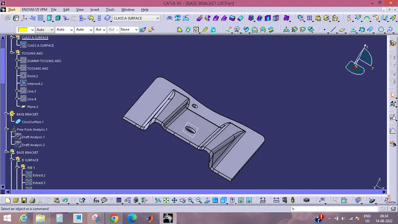
AIM: Create the Base Bracket Plastic component through the given Class-A surface. To begin with, the tooling axis for the given Class-A Surface should be created meeting the requirements of the draft angle and at the end perform the Draft analysis on the model.
Objective:
The primary purpose of this challenge is to develop the Base Bracket Plastic component through the previously provided Class-A surface of the base bracket. This will be accomplished by providing the class-A surface of the base bracket with the 'Tooling axis' and the 'Draft analysis.'
TOOLING AXIS:
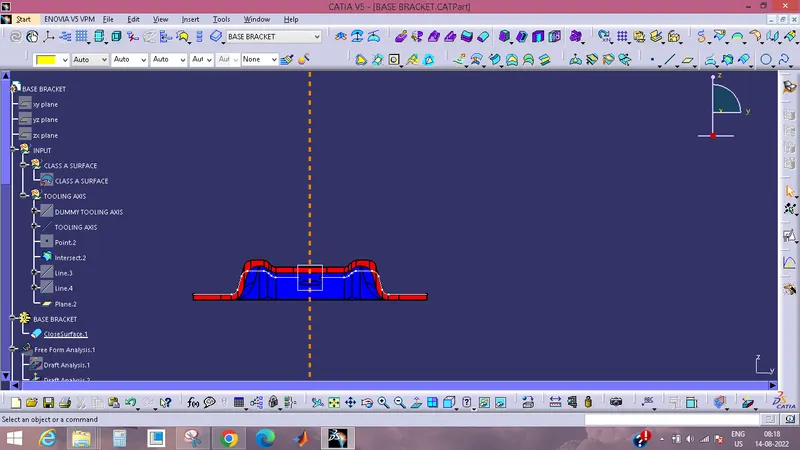
In order to generate the 'Tooling Axis' for the component, we need to carefully inspect and analyse the class A surface. The Z-axis that was provided earlier serves as the tooling axis that is most suited to the component. At the outset, I constructed a dummy as well.
DRAFT ANALYSIS:
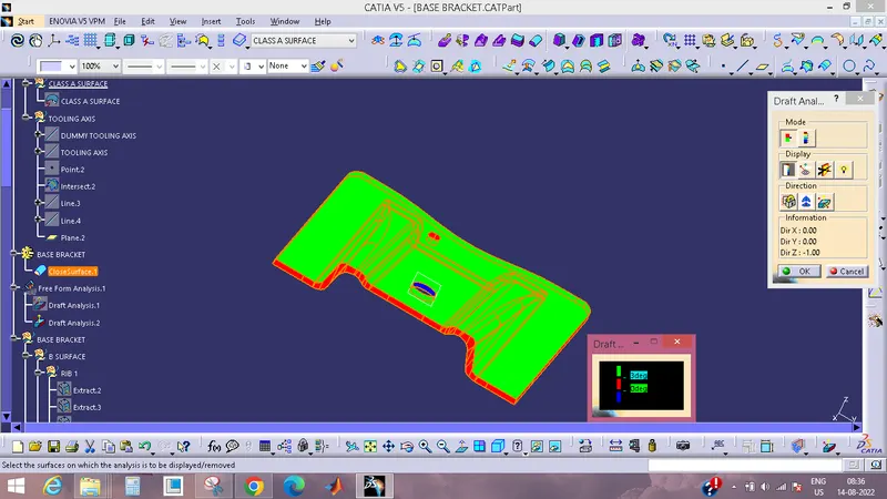
Click the Insert menu, then select Analysis, and then Feature Draft Analysis to carry out draught analysis.
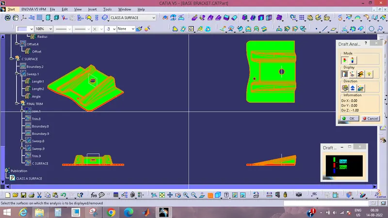
After the drafting analysis toolbar has been launched, proceed to the display block and choose the 'Analysis under the running point' command in order to examine the angle of the class A surface at various sides (ribs and inclined plane angles). The colour scale at the bottom makes it easy to see at a glance if the drafting angle satisfies the requirements of three degrees or not by indicating the corresponding colour: green, blue, or red. After finishing the drafting angle analysis, the next step is to align the compass with the tooling axis of the class A surface and then secure it in place.
Align the compass with the tooling axis and secure it in place by selecting "Use the compass to define the new current drafting direction" in the Direction block of the drafting analysis toolbar (or just click on the compass symbol). The next step is to click the lock icon next to the compass in the direction block once you've brought it to the surface and aligned it with the tooling axis of the class A surface. The draught analysis is complete once the 'ok' button is clicked on the toolbar.
SURFACE OF CLASS B:
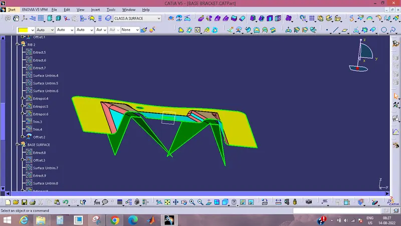
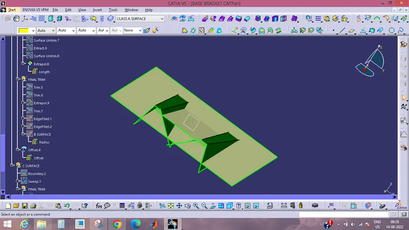
In order to generate the class B surface, I broke the entire surface down into its three component parts—namely, Rib-1, Rib-2, and the Base surface. If we directly offset the class A surface, the fillets may lead to cause an error; therefore, in order to avoid the errors, we need to extract the surfaces, untrim the extracted surfaces, and then extrapolate those untrimmed surfaces with point continuity. Now, sculpt those extrapolated surfaces into the desired form using the appropriate cutting tools. And last but not least, the fillets were prepared for the finishing trim.
Rib-1 and Rib-2:
Base surface creation:
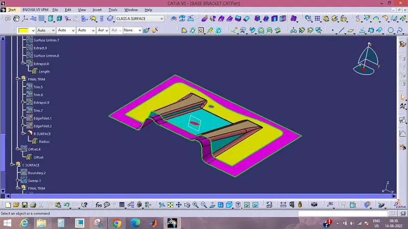
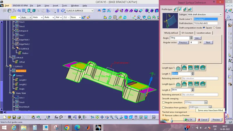
Class C surface using sweep surface def:
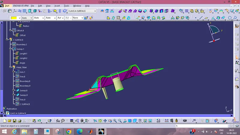
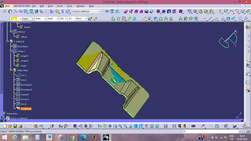
CLOSED SURFACE:
All Four Views:
Publication: