Week 8 - Challenge 2 - Switch Bezel Design
SWITCH BEZEL
DESIGN AND DRAFT ANALYSIS OF SWITCH BEZEL
Aim: This project aims to create a switch bezel plastic component using the given class A surface following the OEM standard. and perform the draft analysis.
Class A-surface
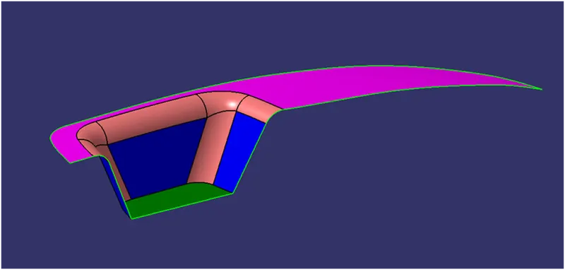
Objective:
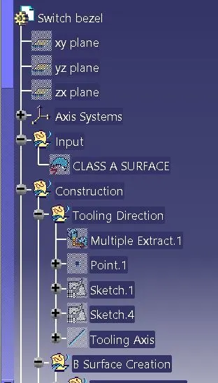
- Ensure Proper Tree Structure.
- Geometrical sets should have a proper name based on the sketches present inside them.
- All the sketches should be created under the Geometrical set.
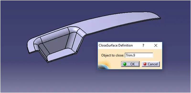
- Use the Close Surface feature to make a solid body from the surface.
- To publish the Tooling Axis, Class A, B, and C surface.
Introduction:
CLASS-A SURFACE: the class-A surface is used in the automotive design industry. it describes the final production surface data for the aesthetic parts.
CLASS-B SURFACE: the class-B surface is the second surface that has a certain thickness from the class-A surface. this surface contains engineering aspects of a model. These must be smooth and "error-free" as well but are not held to the standards that class A surfaces are.
CLASS-C SURFACE: The Class C finish allows more imperfections than Class A or B. Class C is often specified for interior surfaces not readily visible, surfaces that will be covered by another part when assembled, or surfaces.
Design methodology:
- Insert the class A surface of the switch bezel in CATIA software.
- Determining the tooling axis for the switch bezel
- Creation of class B surface.
- Creation of class c surface.
- Join the switch bezel's class A, class B, and class c surfaces and ensure all the surfaces are closed surfaces.
- Use the Close Surface feature to make a solid body from the surface.
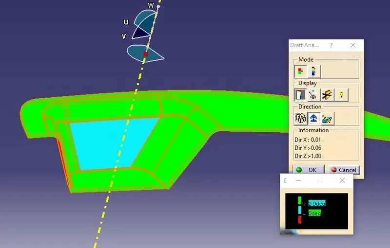
- finally, Perform the Draft analysis on the switch bezel final plastic component
Creating tooling axis:
- The ejection from the mold after manufacturing the interior trim must have the nominal 3-degree draft angle.
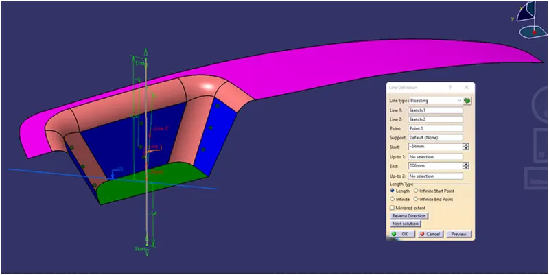
- Hence the tooling directions created by considering the above factor and bisecting method is used.
- The base surface of the class-A was extracted to create a reference point on the surface using the point, create a line in the z-direction and an axis system was inserted to the point
- then using projection intersection along the yz plane is created and the two inclined lines were drawn inside the positioned sketch.
- then bisecting lines with the two inclined lines were created.
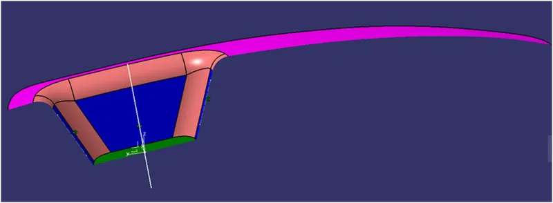
Now the same procedure is done along the xz plane but on xz plane, we only have one surface line so the center point is used to extrude a line along the z-direction and gave a measurement of 6 degrees. from the surface line
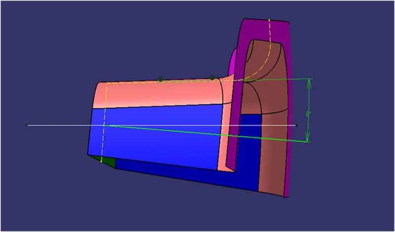
Bisecting these two lines sketch1 and sketch2 the bisecting line is created and published as a tooling axis.
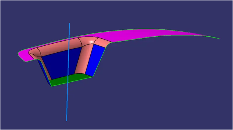
1) CLASS-B SURFACE CREATION: Divide the class-A surface into 3 different surfaces as shown below.
working on these surfaces one by one we have to follow the same procedure for the 1-bezel rest surface, 2-base, and 3-walls.
The first step is to Extract the surfaces untrim and extrapolate the surfaces
Offset the surfaces (by measuring the thickness) here the input is given as 2.5mm
1-Bezel rest surface:
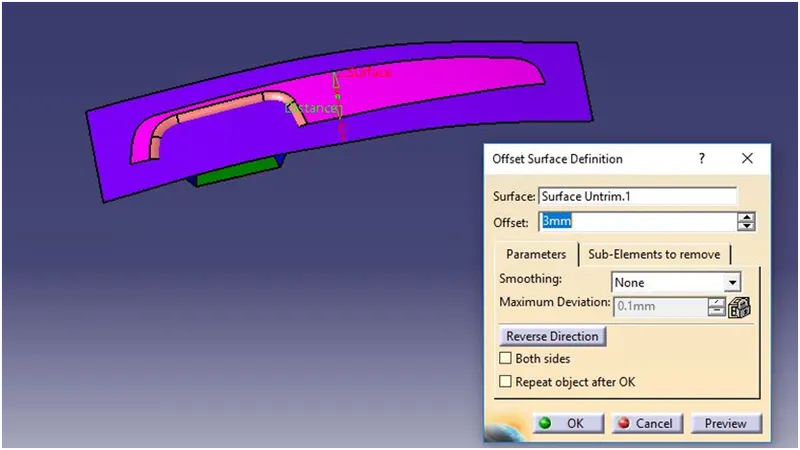
2-walls:
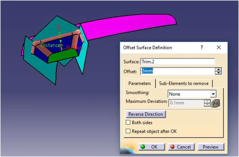
3-Base:
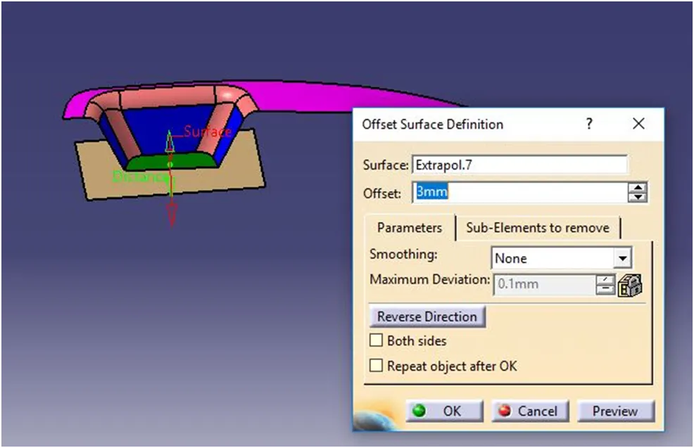
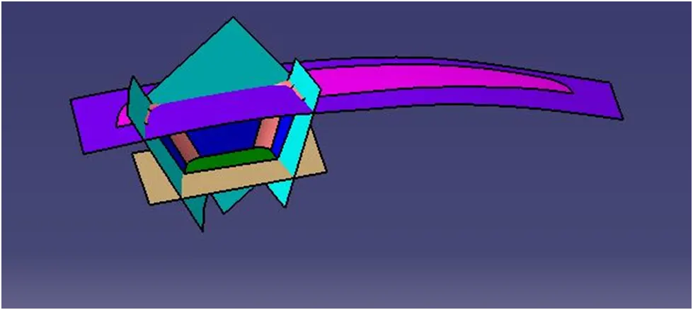
Once all the surfaces are created (i.e, bezel rest surface, walls, and base surface). The required trim operations were performed to form a class-B surface
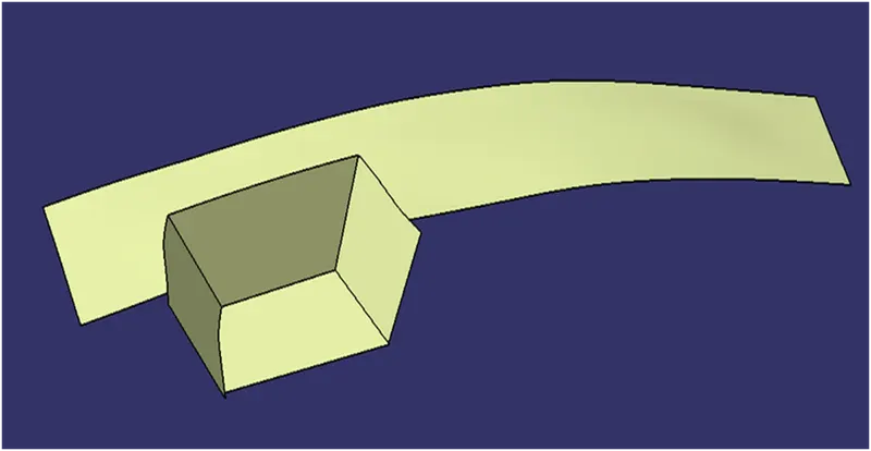
To Perform the fillet operation. Fillet value should be calculated from the Class A surfaces for every edge in the B surface.
The fillet value should be calculated to ensure the component has a uniform thickness.
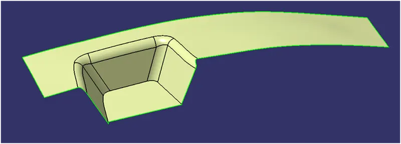
Class-A and Class-B surface
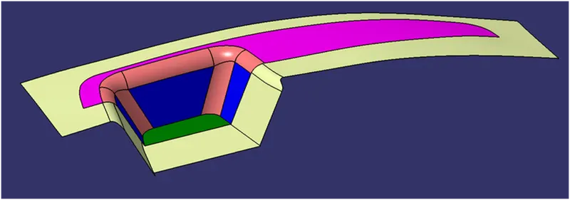
2) CLASS-C SURFACE CREATION:
The edges of the Class-A surface are extracted using the multiple extracts and then converted into smooth curvature to avoid the patches.
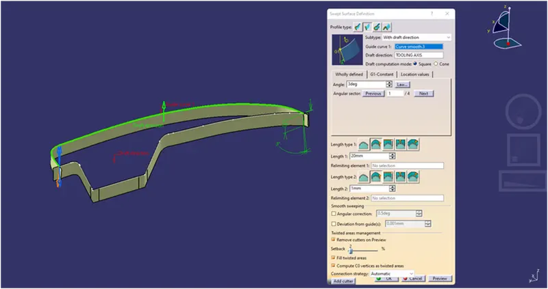
Sweep operation is performed (with draft direction) selecting the smooth curves as the guide curve and tooling axis as the direction and draft angle as 3deg
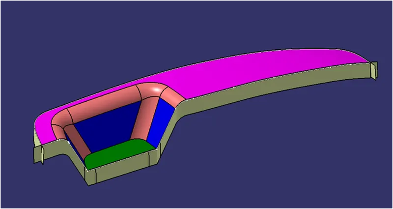
Join class-A and class-C surfaces. Make sure that there is no unnecessary boundary present, if there is then increase the merging distance to not more than 0.003mm. and even after there is some unwanted boundary, extrapolate class-A by a small distance and trim it with class-c instead of joining them.
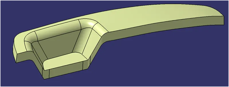
Then trim the class-C surface with the class-B surface.
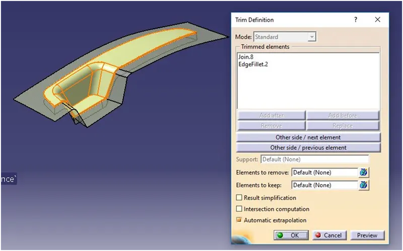
THE CLASS-C SURFACE
Go to the part workbench by using the Close Surface feature we created a solid body from the surface.
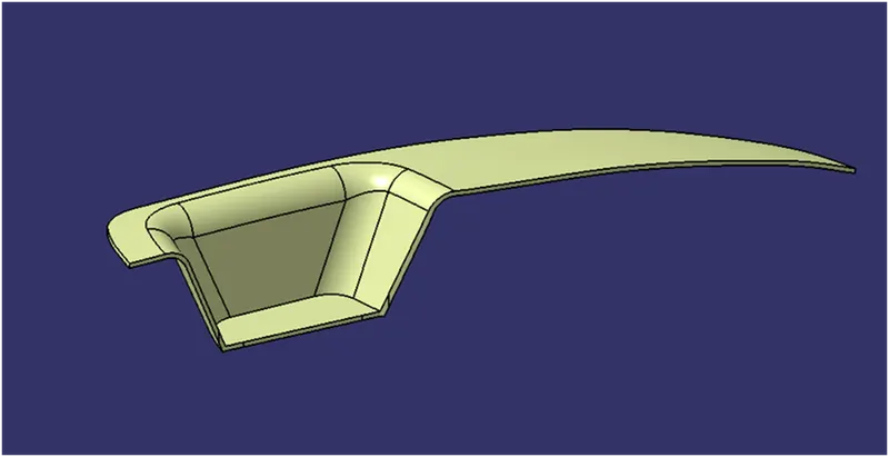
Go to the part workbench by using the Close Surface feature we created a solid body from the surface.
Draft Analysis:
Feature Tree:
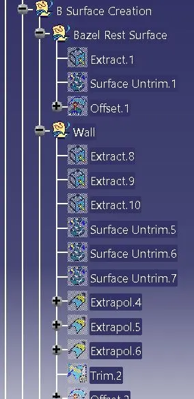
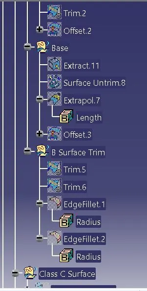
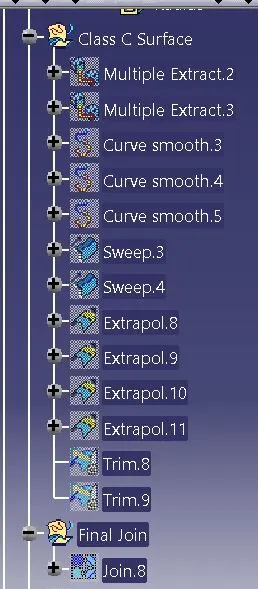
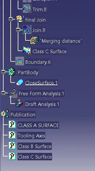
Different Views:
1) Isometric View:
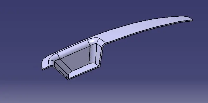
2) Top View:
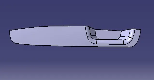
3) Front View:
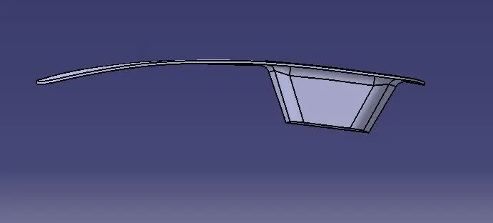
4) Right Side View:
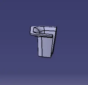
Conclusion: Thus i've created a design of Switch Bezel and its draft Analysis.