Hood design-Week 2
Hood Assembly using NX CAD
Aim/Objective: -
Step 1: To Modeled the Inner Panel first using outer panel skin data for reference with the help of NX CAD
Step 2: Provide hemming to outer panel
Step 3: Assemble the Hinge, Striker, outer Panel & Inner Panel.
Brief Introduction: The Hood is main part of the vehicle which is also called as Bonnet it covers the frontal area containing Engine compartment and all other component and always exposed to heat, frontal crash, climate condition etc…during the design of hood should meet the safety requirement like Pedestrian safety, hood head zone for Latch striker, and for frontal collision
It consist of following component below
1) Outer Panel Skin
2) Inner Panel
3) Hinge Assembly
4) Striker Assembly
Data to be used:
Hood Thickness Information
- Outer Panel Thickness = 0.75mm
- Inner Panel Thickness = 0.75mm
- Reinforcement Thickness = 1.5mm
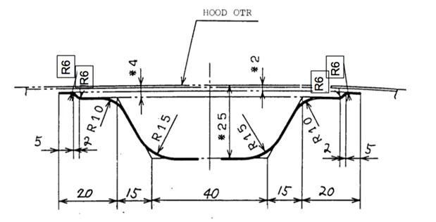
Master sketch:
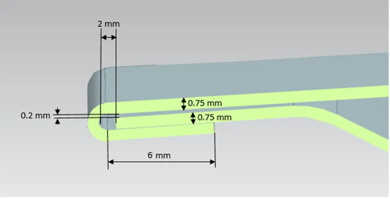
Hemming Data:
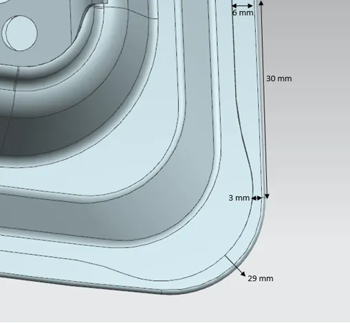
Relief rear section:
Front relief:
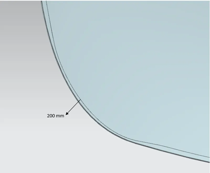
- Outer Panel: the outer panel is attached to an inner panel by hemming so there must be provided flange for making perfect hemming operation. After hemming operation the relief should be provided for matching the position of inner panel
Command Used:
- Offset curve on face
- offset curve on surface
- Law Extension
- Offset surface
- Trim sheet
- Face blend
- Mirror Geometry
- Sew
- Thicken
- Appearance
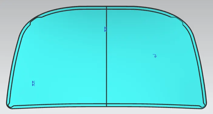
Front Relief
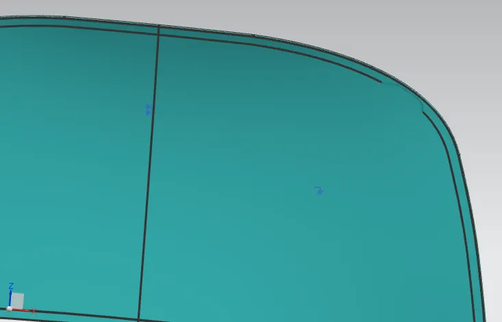
Corner Relief
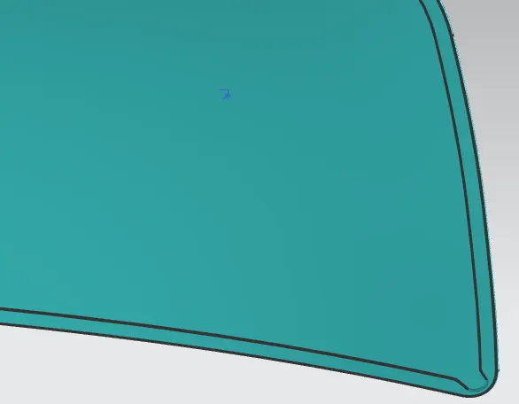
Hemming Flange
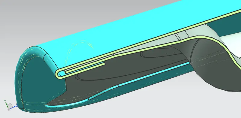
- Inner Panel: Inner panel is which has directly exposed to the engine compartment and has to provide the rigidity to the outer panel. It is made using Skin data of outer panel & Master Section for creating flanges and embosses
Command used:
- Offset surface
- Trim Sheet
- Law Extension
- Extend Sheet
- Edge blend
- Face Blend
- Offset curve
- Bridge curve
- Projected curve
- Embosses
- Mirror Geometry
- Sew
- Thicken
- Appearance
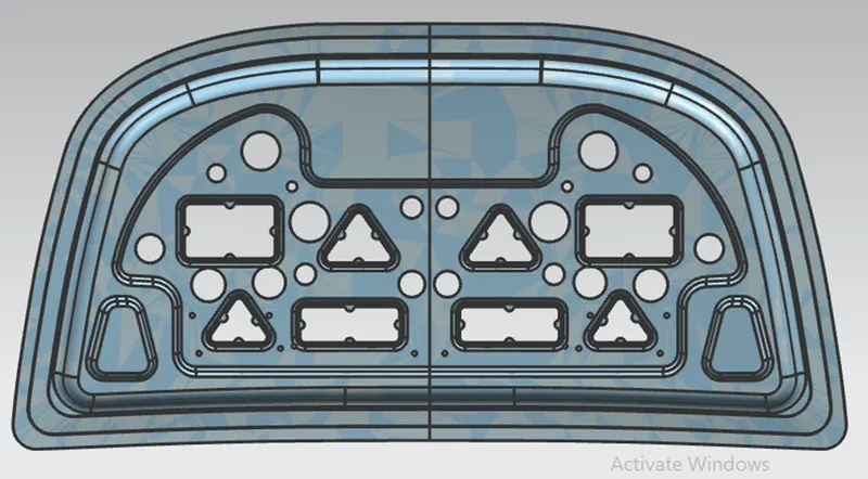
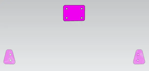
- Reinforcement : The main aim to provide reinforcement to the inner panel is to provide strength to the panel its thickness is higher than the inner panel and its values varies according to the requirement. It is provided on hinge & Latch position
Command Used :
- Create New
- wave Geometry Link(Associates)
- thicken
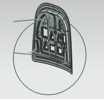
- Latch Trajectory: Latch Trajectory is given by the circle drawn from the hinge axis after fixing the hinge position. Hinge axis is passing through the center point of Hinge. After giving some assembly constraint we can fix its position on the inner panel the axis of Striker & the Tip of the striker must be tangent to the trajectory for proper mating condition.
Commands Used :
- Assembly Constraint
- Link Face
- Point
- Wave Geometry link
- Sketch
- Law Extension
- Appearance
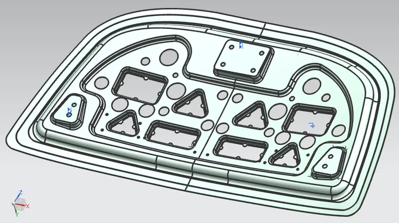
- Emboss : For making better stiffness to the inner panel we have provide the embosses throughout the panel. The Shape and size may be differing as per the requirement, frontal collision & Force Distribution. The design of hood should be if the frontal collision takes place then the force distribution will be away from the passenger. So for this purpose embosses provided.
Command Used:
- Sketch
- CSYS Plane
- Profile fore sketch
- Project curve
- Emboss
- Edge/Face blend
Mastic Data: The Purpose of providing this sealant is only related to the appearance of hood. As we Know during the unibody making all parts are welded together by spot welding except Hood. Because if we provide the spot welding on hood then the Spot mark will be appears on the hood so the will be odd but other parts are hidden by some other parts so need not to provide the mastic Sealants to other body parts. Mastic Sealant is used to stick the inner surface of outer panel & Inner Panel. Mastic points are arranged in such a way that it covers Large away from the hemming which can vibrate by doing this if provide on hemming flange
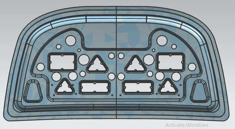
- Hemming flange : For connecting the inner panel assembly to the outer panel of the hood hemming flange is provided by hemming Process. It is a forming process in which the outer edges are folded over another parts in order to achieve tight fit. The accuracy of hemming operation important as it affect the appearance of the surface and Surface quality
Command used :
- offset curve
- offset surface
- Trim Sheet
- Face Blend
Sheet Matel Operation For Car Hood Manufacturing Process
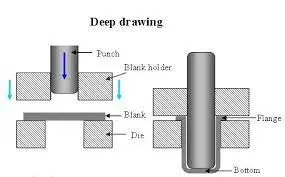
1. Deep Drawing : Deep drawing is a sheet metal forming process in which a sheet metal blank is radially drawn into a forming die by the mechanical action of a punch. It is thus a shape transformation process with material retention. The process is considered "deep" drawing when the depth of the drawn part exceeds its diameter
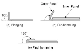
2. Hemming : Hemming is a sheet metal forming process in which sheets are joined by bending it to 180°. Automotive body panels and automotive parts such as deck-lids, trunk-lids, doors, hoods and tailgates are formed by hemming process. In this process, usually a sheet is bent with the help of inner sheet in three different stages.
3. Embossing : Sheet metal embossing is a stamping process for producing raised or sunken designs or relief in sheet metal. This process can be made by means of matched male and female roller dies, or by passing sheet or a strip of metal between rolls of the desired pattern
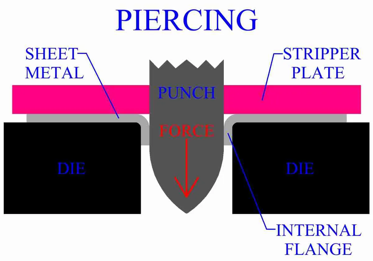
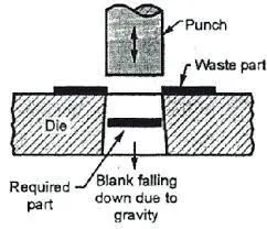
4. Piercing :
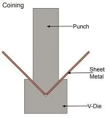
5. Coining : Coining fabrication is a basic type of bending in which the workpiece is stamped between the punch and die. Both the punch tip and the punch actually penetrate into the metal past the neutral axis under a high amount of pressure.
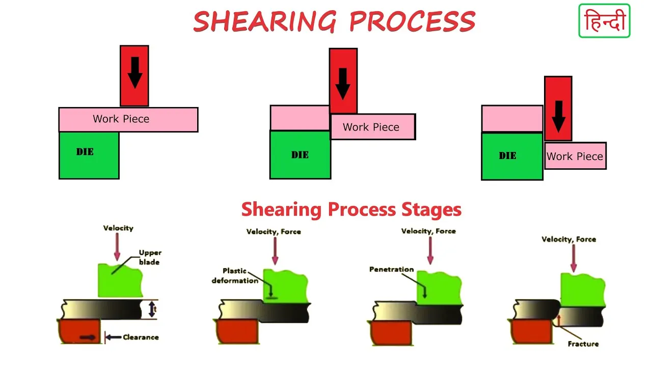
6. Shearing/Trimming : Shearing is the process of cutting sheet metal to size out of a larger roll or flat stock. As the material moves through the shear machine, cutting blades come together in order to fracture the material into separate, smaller pieces. This process creates quality clean cuts that can be repeated quickly.
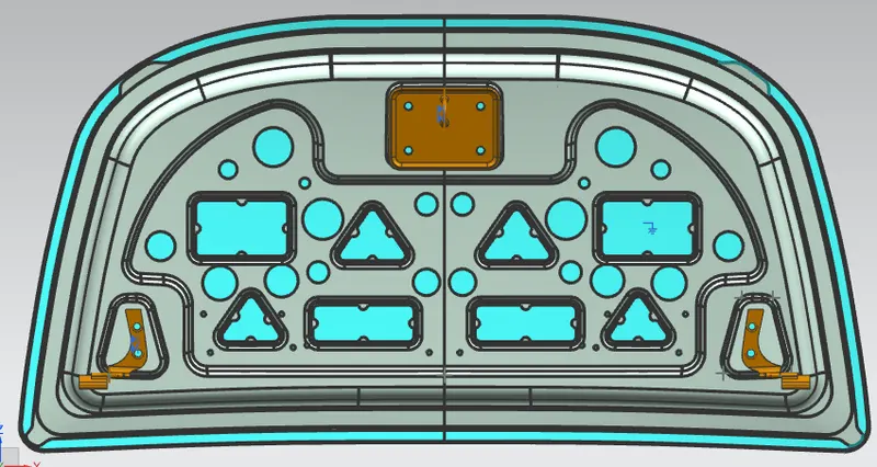
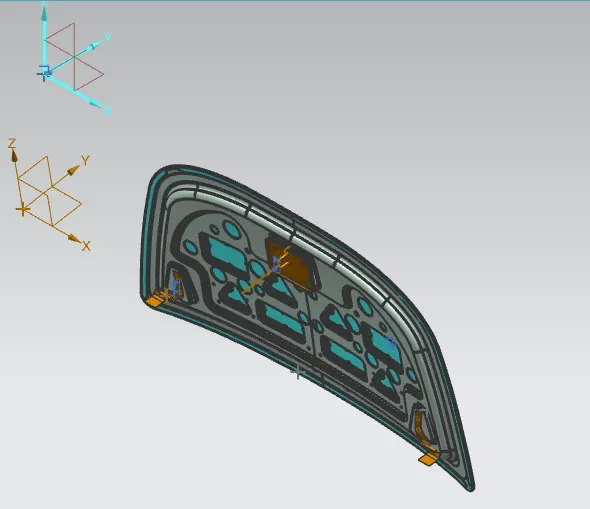
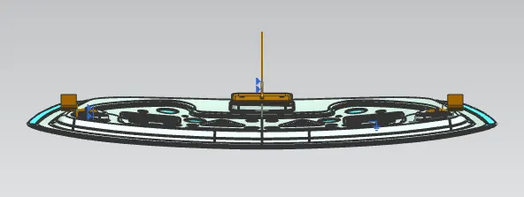
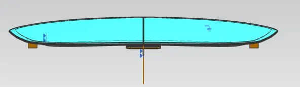
- Final assembly :
- All views
- Isometric View:
2. Bottom View:
3. Top View :
4. Right Side View :
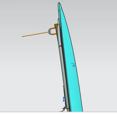
- Conclusion : Finaly the Design of Hood Assembly has been Completed by using different assembly component Like Inner Panel, Hinges Striker & Outer Panel.Assembeled them together by giving some relation. using NX CAD Software and Parameter.