Photo Realistic Rendering
Modeling the American Chopper bike and Create a Photo realistic Render Environmental image
Aim/Objective: -
Step 1: To create different parts of American chopper bike using solid work station on different planes
Step 2: To Creating Assembly of bike using Different parts
Step 3: To provide photo realistic render image using solid work visualizer.
Brief Introduction: The American chopper bike has made by using part modeling making different parts by using solid work software. Below is the following parts of chopper:-
1) Transmission Belt
2) Kick Stand
3) Front Fender
4) Rear fender
5) Chain Drive
6) Oil Tank
7) Padel
8) Fork
9) Front wheel
10) Rear wheel
11) Engine
12) Chassis
13) Gas Tank
Let’s get Start with Each part Modeling
- Transmission Belt: Transmission Belt is made from Flexible material it provide or transfer the Motion/Power between two shafts.
Command Used
1) Front Plane
2) 2D Sketch
3) Boss Extrude
4) Fillet
5) Smart Dimension
6) Appearance
Image of modeled part
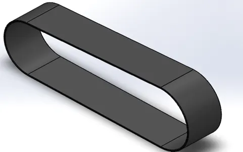
2. Kick Stand: It is a Metal Part which is pivoted to the Left/Right side of Bicycle/Bike for providing support to vehicle
Commands used
1) 2D Planes
2) 2D Sketch
3) Reference Plane
4) Smart Dimension
5) Loft
6) Dome
7) Cut Extrude
8) Split
9) Boss Extrude
10) Fillet
Image of Modeled Part
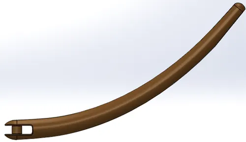
- Front fender: It is used to cover up the side front wheel
Command Used
1) 2D Planes
2) 2D Sketch
3) Smart Dimension
4) Revolve
5) Split
6) Fillet
7) Appearance
Image of Modeled Part
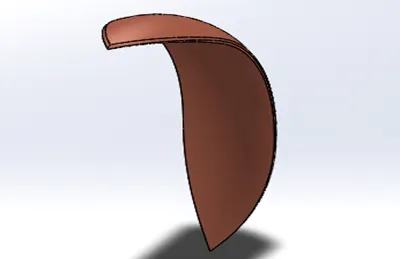
- Rear Fender: It is also used to cover up of Rear wheel.
Commands Used
1) 2D Planes
2) 2D Sketch
3) Smart Dimension
4) Revolve
5) Split
6) Fillets
7) Appearance
Modeled part Image
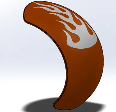
- Chain Drive: Chain drive is used to transmit the power from engine to Rear wheel by connecting between two sprockets
Commands Used
1) 2D Planes
2) 2D Sketch
3) Smart Dimension
4) Sketch Block
5) Boss Extrude
6) Curve Pattern
7) Fillet
8) Mirror
9) Appearance
Modeled Part Image
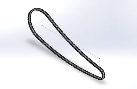
- Oil Tank: It is the part of Vehicle which is mounted below the seat of the chopper & used to store the Engine oil for lubrication
Commands Used
1) 2D Planes
2) 2D Sketch
3) Smart Dimension
4) Boss Extrude
5) Combine
6) Fillet
7) Shell
8) Appearance
Modeled Part Image
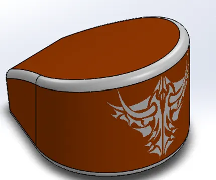
7. Padel: It is also known as gear shifter/ Foot Lever used to shift the gear by pressing or pulling from feet.
Commands Used
1) 2D Planes
2) 2D Sketch
3) Smart dimension
4) Boss Extrude
5) Fillet
6) Revolve
7) Dome
8) Chamfer
9) LPattern
10) Mirror (LHS)
11) Appearance
Modeled Part Image
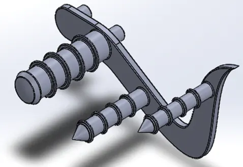
8. Fork: Fork is Just Like a steering System and used to turn left & right of the vehicle it contains steering handle, Headlight, Throttle control, Brakes & Suspension
Commands Used
1) 2D Planes
2) 2D Sketch
3) Smart Dimension
4) Revolve
5) Boss Extrude
6) Fillet
7) LPattern
8) Cut Extrude
9) Dome
10) Cut Revolve
11) Body- move/copy
12) Projected Curve
13) Sweep
14) Reference Planes
15) Mirror
16) Combine
17) Appearance
Modeled Part Image
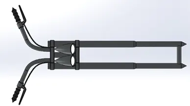
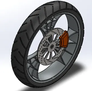
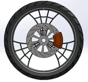
- Front Wheel: Wheel is main part of the vehicle without it vehicle not able to move ahead by rotary motion of wheel vehicle is only move ahead.
It contains the following part:-
- Rim
- Disk brake (Rotor)
- Caliper
- Tire
Commands Used
1) 2D Plane
2) 2D Sketch
3) Smart Dimension
4) Boss Extrude
5) Cut extrude
6) Cut revolve
7) Cirpattern
8) Chamfer
9) Fillet
10) Combine
11) Appearance
Modeled Part Image
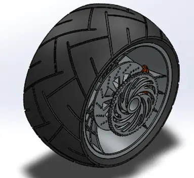
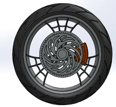
- Rear Wheel: It contains following part
- Rim
- Disk Brake (Rotor)
- Caliper
- Sprocket
- Tire
Commands Used
1) 2DPlanes
2) 2D Sketch
3) Revolve
4) Offset entities
5) Mirror entities
6) Boss extrude
7) Cut extrude
8) Cirpattern
9) Combine
10) Fillet
11) Chamfer
12) Appearance
Modeled Part Image
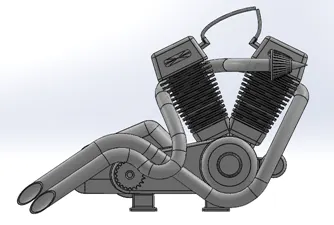
- Engine: Engine is the heart of the vehicle the bike engine is mostly four stroke petrol engine which provide the power to the vehicle.
Commands Used
1) 2D Plane
2) 2D Sketch
3) Smart Dimension
4) Boss Extrude
5) Fillet
6) Revolve
7) Reference Plane
8) Cirpatern
9) Dome
10) Cut Extrude
11) Chamfer
12) Lpattern
13) Mirror
14) Cirpattern
15) Projected Curve
16) Composite Curve
17) Swept Boss/Base
18) Split
19) Appearance
Modeled Part Image
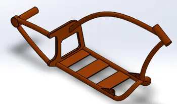
- Chassis: It is the frame part of the Vehicle in which engine and all other parts are mounted and make an assembled bike
Commands Used
1) 2D Plane
2) 2D Sketch
3) Smart Dimension
4) Projected Curve
5) Swept Boss/Base
6) Mirror
7) Boss Extrude
8) Cut Extrude
9) Chamfer
10) Fillet
11) Dome
12) Reference Plane
13) Split
14) Combine
15) Revolve
16) Appearance
Modeled Part Image
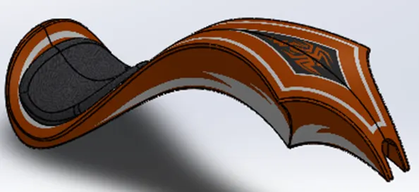
13. Gas Tank: It is also known as fuel tank used to store the gasoline. Which provide power to the engine after burning.
This tank contains three Decals
Command Used
- 2D Plane
- 2D Sketch
- Reference plane
- Surface sweep
- Surface trim
- Projected curve
- Surface Loft
- Boundary Surface
- Mirror
- Surface knit
- Split Line
- Surface Extrude
- Fillet
- Cut Sweep
- Shell
- Appearance
Modeled Part Image
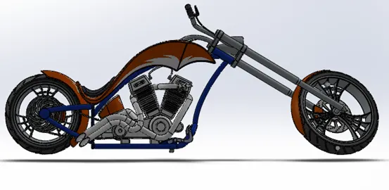
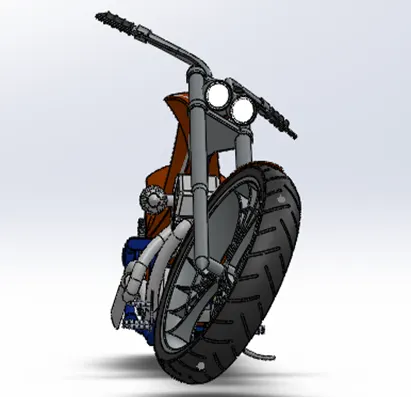
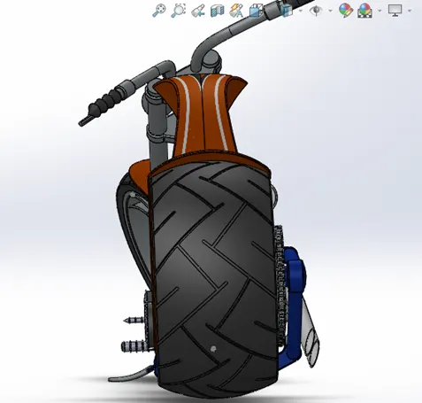
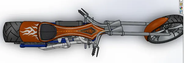
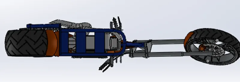
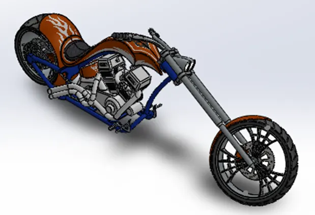
Assembly of American Chopper Bike: In this the whole Bike was assemble by importing the different part modeled one by one randomly. By giving them some mate relation they properly fitted to their defined position. Below is the different views of chopper shown
Front View:
Right Side View:
Left Side View:
Top View:
Bottom View:
Isometric View:
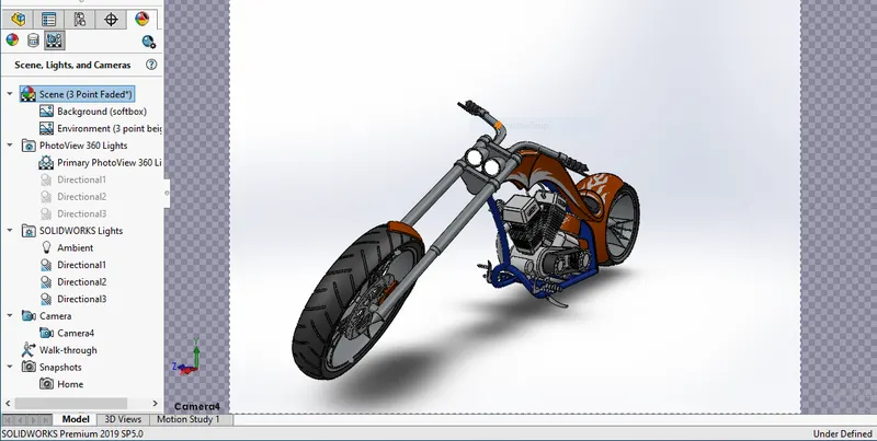
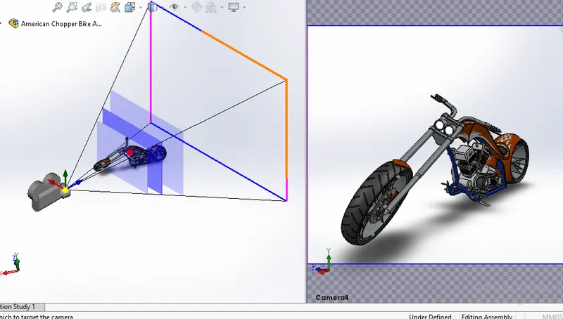
Camera Setup View:
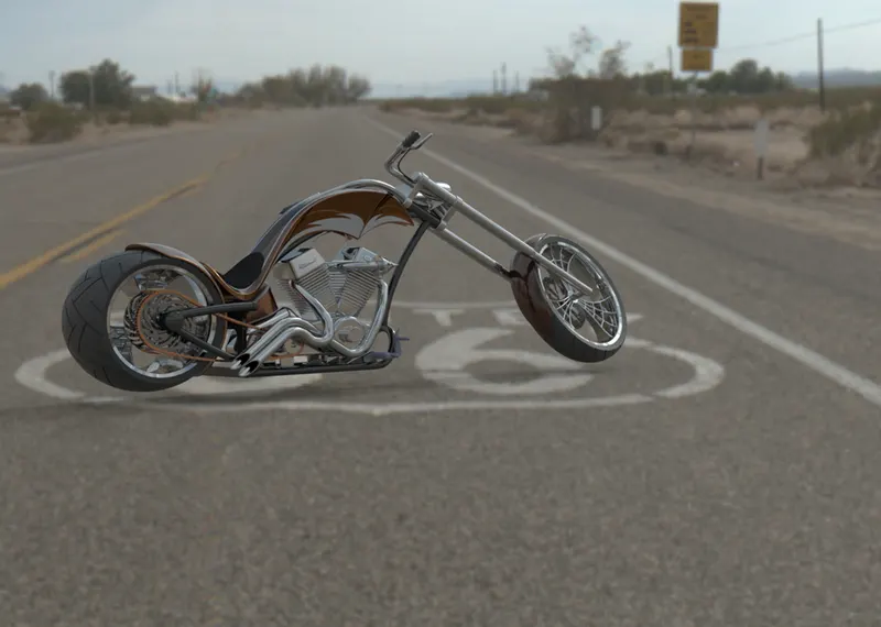
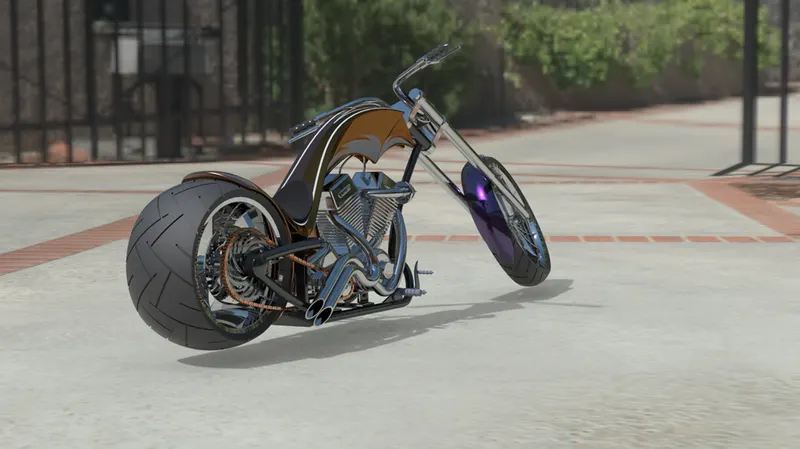
Photorealistic Render using Solid Work Visualizer:
Route 66:
Sunny Driveway:
Conclusion: Thus the American chopper bike assembly has been completed. As par the Design approach& Sequence follow by modeling first individual part & assemble them by providing some mate relation like Coincident, Concentric etc...