Week 8 - Challenge 2 - Switch Bezel Design
Aim: To develope a solid cad part for the given Bezel Switch class-A surface.
Procedure:
Creation Of Tooling Axis:
1. A suitable tooling direction (z-direction) is determined through visual analysis.
2. Using intersection command,Point and different line commands, tooling axis is created.
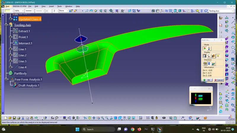
Creation of Draft Analysis on Class-A surface:
1. Click Insert>Analysis>Feature Draft Analysis.
2. The Compass is placed on the tooling axis and checked for the given draft angles on the Class-A surface.
Creation of B- Surfaces:
1. The Boundary command is used to check continuity of the curve on the surfaces.
2. Using Extract,Extrapolate,Offset and Trim commands on Flat Surfaces,Class-B surface is drawn.
Creation of C-Surfaces:
1. Using Sweep command with draft direction and Fillets command on edges,Class-C surface is drawn.
2. Using Trim commands on Class-A and Class-B surfaces ,the final output is drawn.
Creation of Part Object:
1. The part Design tab is opened.
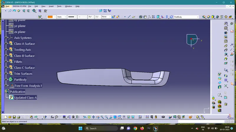
2. Using Close Surface command on final surface,the final plastic cad part model is created.
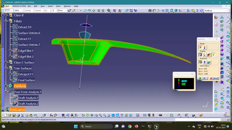
Creation of Draft Analysis on Part Model:
1. Click Insert>Analysis>Feature Draft Analysis.
2. The Compass is placed on the tooling axis and checked for the given draft angles on Part Model.
Various views of Final Model Part:
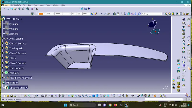 Isometric View
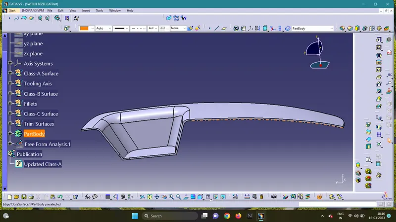 Front View
 Top View