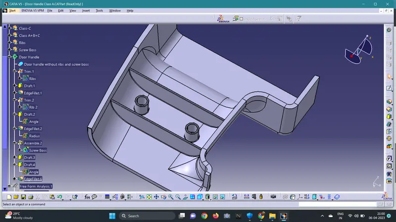
Week 10 - Challenge 1- Attachment Feature Creation (Ribs & Screw Boss)
Aim:
- To create a tooling axis and perform draft analysis on the given class-A surface.
- To create class-B,class-C surfaces and make the part material.
- To create ribs and screw bosses as per the given drawing.
Procedure:
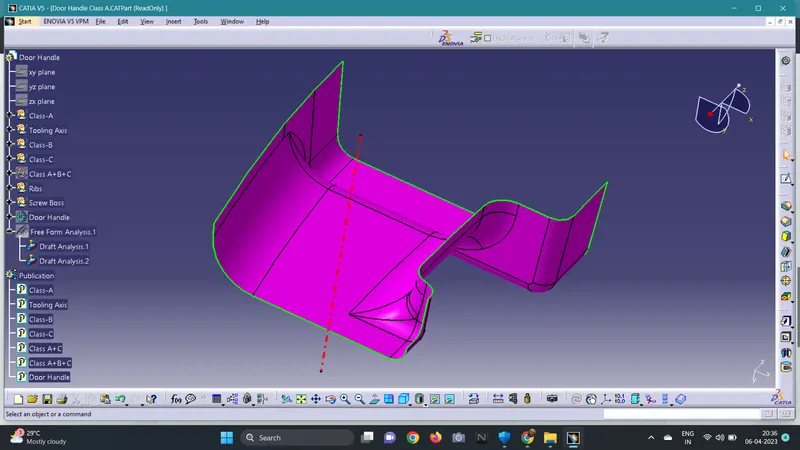
Creation of Tooling Axis:
- The class-A surface is analysed for suitable tooling direction.
- A flat surface is extracted and a point is created on the surface and using the line command ,the tooling axis is created.
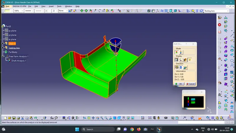
Creation of Draft Analysis:
- After creating the tooling axis, select Insert>Analysis>Feature Draft Analysis.
- Select the compass and coincide it with the tooling axis and lock the compass.
- Give the draft value as 3 degree.
- Click on the surface and draft analysis is done.
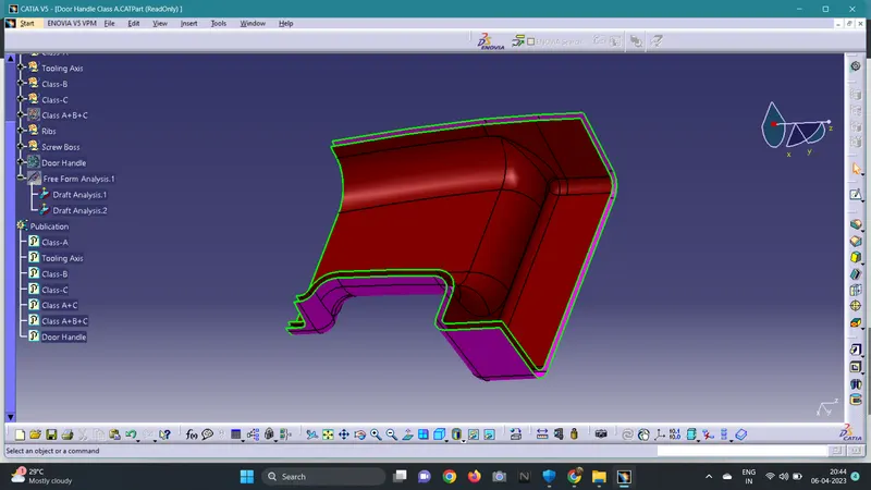
Creation Of Class-B Surface:
- The class-A surface is offsetted for the required thickness i.e., 2.5mm.
- The patches in the offsetted surface is cleared by using boundary and fill commands.
- The class-B surface is joined.
Creation of Class-C Surface:
- The class-C surface is created by sweeping the class-A surface boundary.
- The boundary and sweep commands is used for the above step.
- In this challenge, extrapolate and trim commands are also used to arrive the class-C surface.
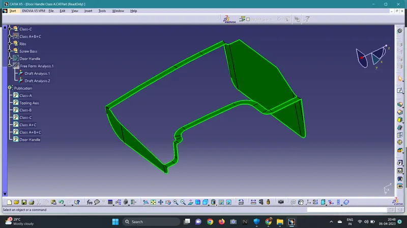
Creation of Class-A+B+C surface:
- The Class-A and class-C surface are joined using join command.
- The class-B surface is extrapolated.
- Using the trim command, Class-A+B+C surface is obtained.
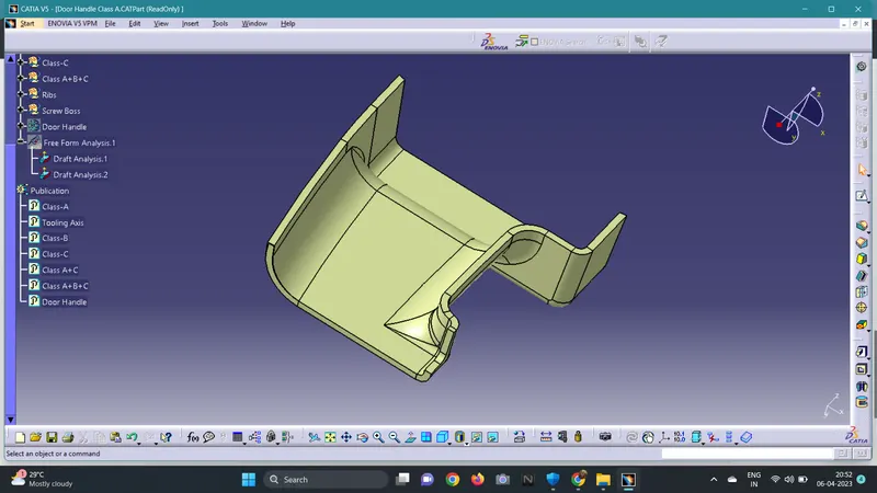
Creating Cad Part :
- The part design window is opened.
- Using the close surface command, the final cad part is obtained.
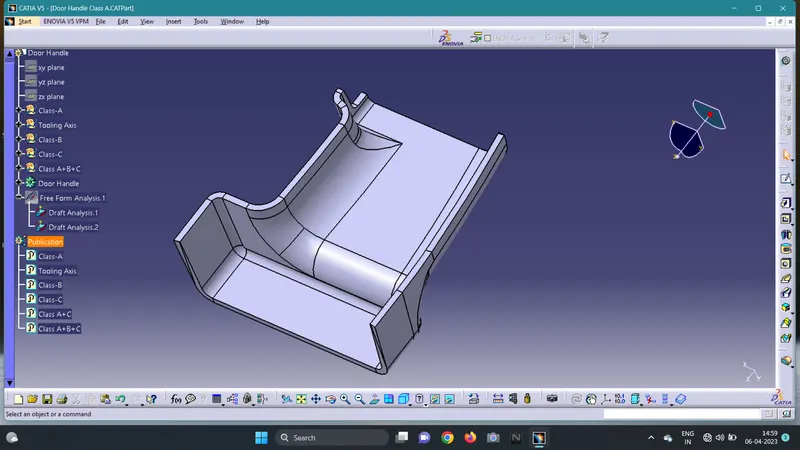
Creating Ribs:
- Using positioned sketch, the ribs are drawn according to the requirements.
- Using pad command, the ribs are designed with a thickness of 1mm(0.4*2.5=1) , height of 12mm(4.8*2.5=12) and a draft angle of 0.5 degree and edge filleted for 0.25 mm(given).
Creating Screw Bosses:
- Using positioned sketch, the screw bosses are drawn according to the requirements.
- Using pad command, the screw bosses are designed with a inner diameter of M6 screw of 5.2mm,outer diameter of 7.2mm, and height of 7.5mm(3*2.5=7.5) and a draft angle of 0.5 degree and edge filleted for 0.25 mm.