Week 8 - Challenge 1 - Base Bracket Design
Aim:
To design a part model from the given class-A surface.
Procedure:
Creation of Tooling Axis:
1. The Class- A surface is checked for discontinuity using Boundary or Join command.
2. The model is analyzed manually and most suitable direction for tooling axis is determined.
3. In the above given Class-A surface, the Z- direction is choosed to create tooling axis.
4. Tooling axis is created on Z-direction by bisecting two lines created on the vertices of boundary curve formed by the intersection of Class-A surface and a plane formed through the point centered to the circle.
Creation of Draft Analysis:
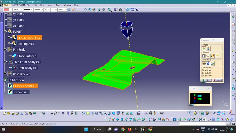
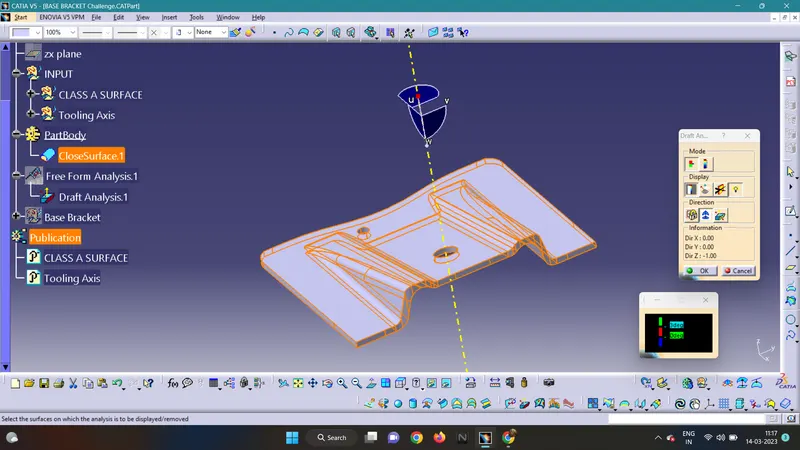
1. Select Insert>Analysis>Feature Draft Analysis.Select the compass and align it with the tooling axis.
2. Click on the Class-A surface and check Whether it is in permissible limit for the given draft values.
3. The column value is given as 3 deg.The Surface will show in green colour.
Draft Analysis of Class-A Surface:
Draft Analysis of Final Component:
Creation of Class-B Surface:
1. Flat surfaces from Class-A surface is extracted,un-trimmed,extrapolated,trimmed and offseted to the required dimensions.
2. In this problem the offset dimensions i.e., thickness is 2.5mm.
3. The Ribs and base surface is formed using step 1 and thus class-B surface is formed.
Creation of Class-C Surface:
1. Class-A surface boundary is extracted and sweep command is used for holes in the surface to get the Class-C surface.
Creation of Final Output:
1. Class-A and Class-C surfaces are joined together and Trimmed with Class-B surface.
2. Enter the part design and use close surface command to convert the final model into part design.
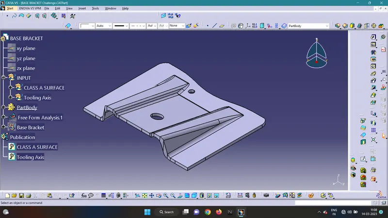
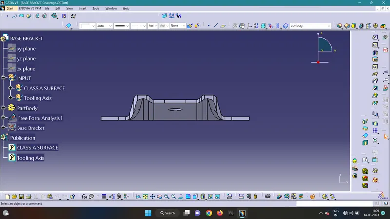
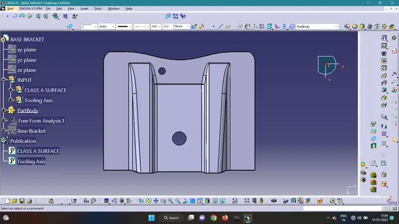
Final Part Model with Isometric,Front,Top Views: