Week 8 - Challenge 2 - Base Bracket Design
Base Bracket Design
Create the Base Bracket Plastic component through the Class-A surface. To begin with, the tooling axis for the given Class-A Surface should be created meeting the requirements of the draft angle and at the end perform the Draft analysis on the model.
Understanding Draft for Plastic products
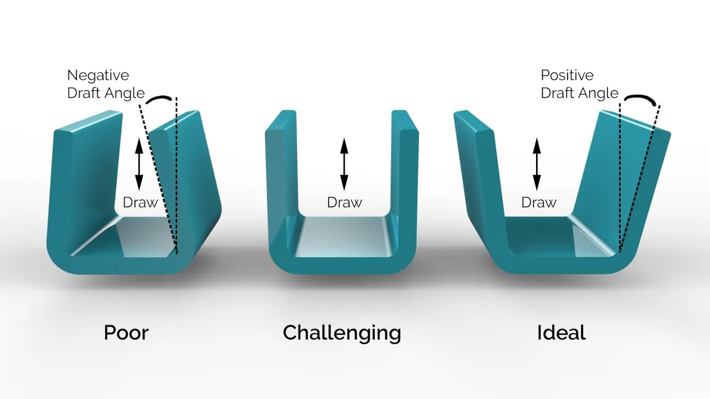
When developing parts for plastic molding, applying draft (or a taper) to the faces of the part is critical to improving the moldability of your part. Without it, parts run the risk of poor cosmetic finishes, and may bend, break, or warp due to molding stresses caused by the plastic cooling. Equally important, an absence of draft may prevent parts from ejecting from the mold, damaging not only the parts, but possibly the mold itself a costly and time consuming detour.
Create the Base Bracket Plastic component and perform draft analysis using CATIA V5
1. Creating the tooling axis
Create Class A surface using the skin file of the Base Bracket-
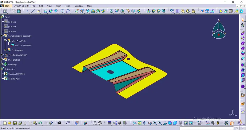
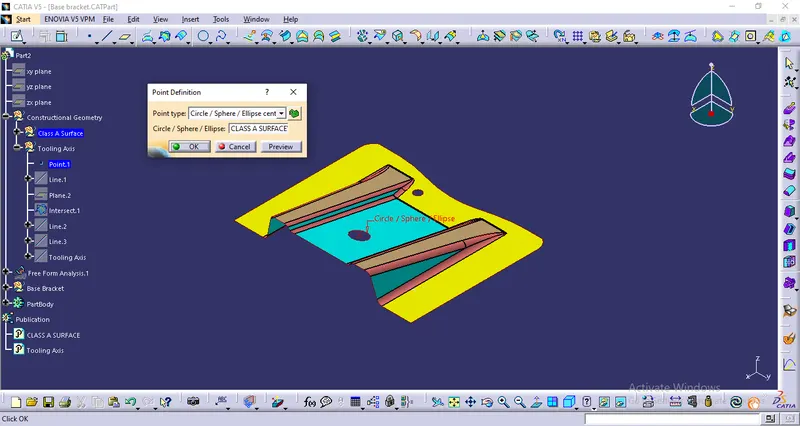
Crete a center point-
Create a dummy tooling direction -
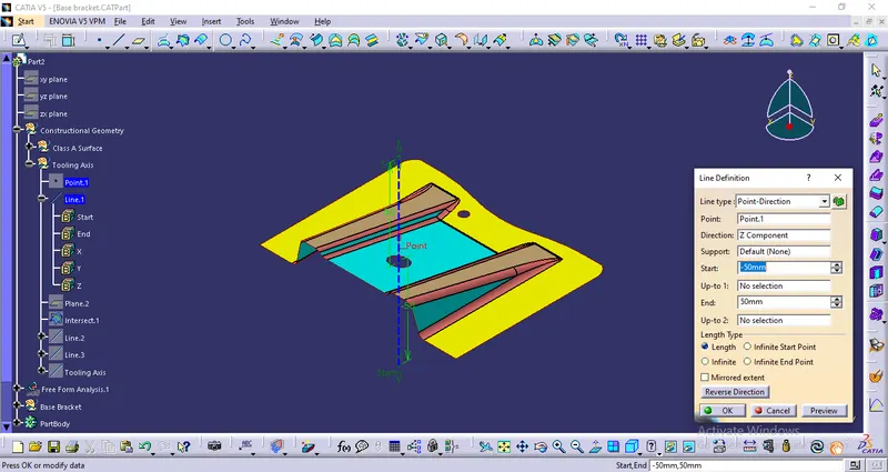
- On the basis of visual study create an appropriate dummy tooling direction using center point.
- For this consider all the aspects like holes and undercuts.
Intersect the class A with YZ plane-
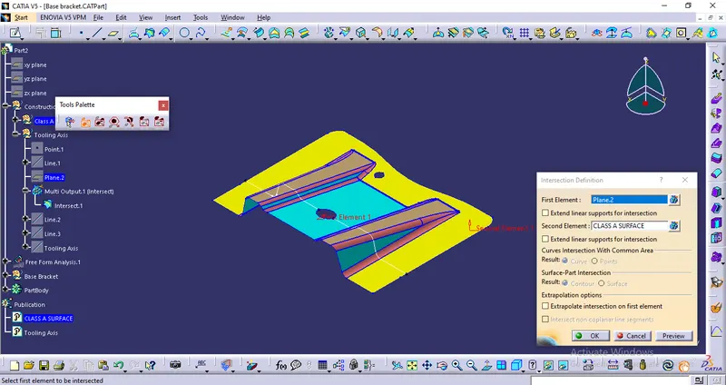
Create the final Tooling Axis-
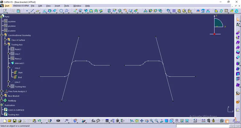
- Using the intersect curves draw lines on the edges of the body
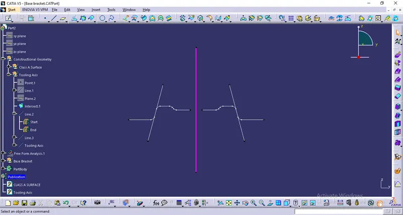
- Using these two lines, create a bisecting line (Tooling Axis)
- Publish the class A surface as well as tooling axis for convinience.
2. Draft Alanysis
Use the tooling direction-
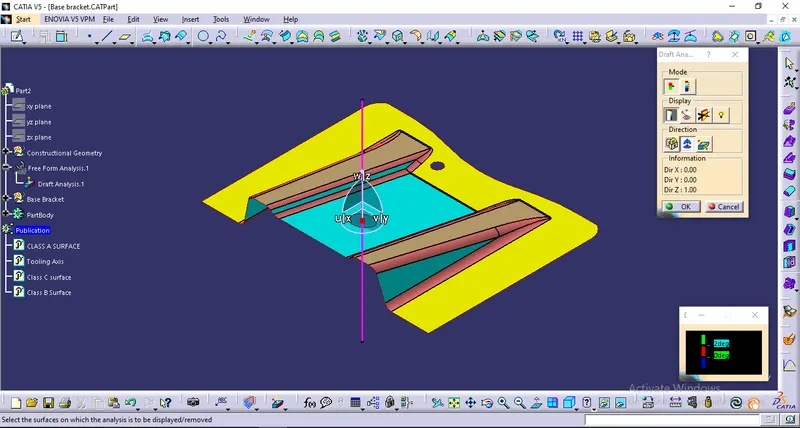
- Set the compass in the tooling direction.
Conduct draft analysis -
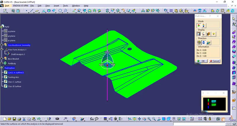
- Analyze at 3 degree required draft.
3. Creating Class B Sufrace
Create the ribs-
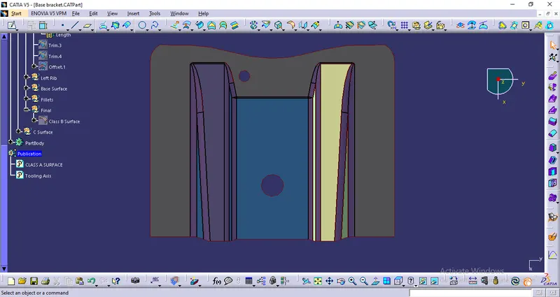
- Extract the surfaces for rib from A Surface.
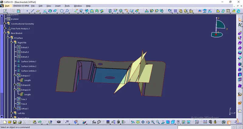
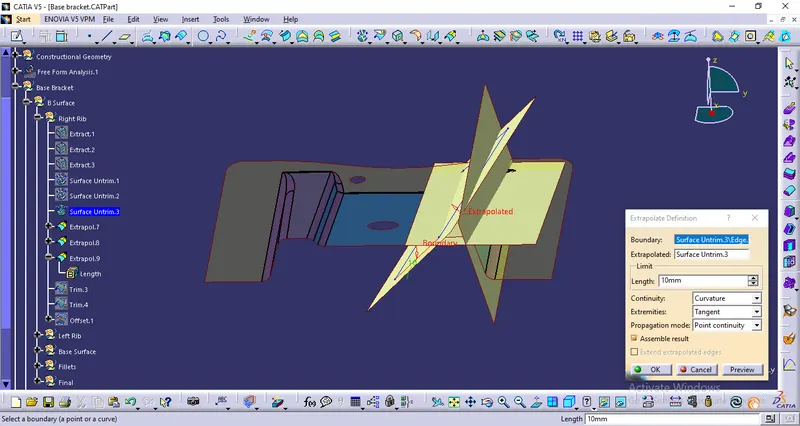
- Untrim those surfaces and extrapolate 10 mm
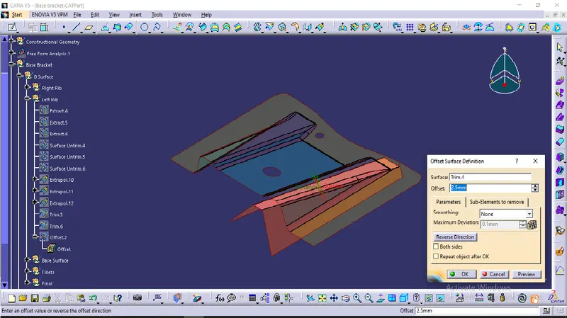
- Trim off the surface to get rib surface offset of 2.5 mm.
Similarly create other rib-
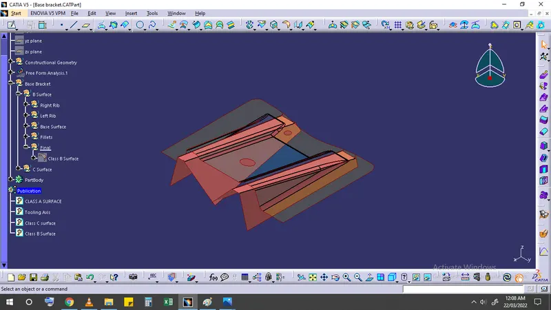
Create base Surface-
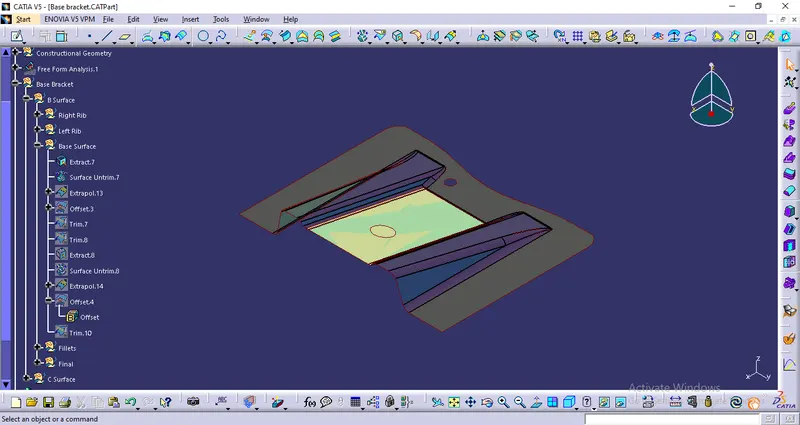
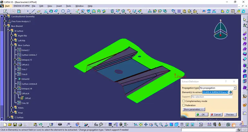
- Extract the surfaces for base surface from A Surface.
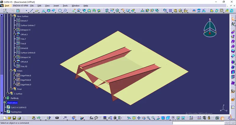
- Untrim those surfaces and extrapolate 10 mm with an offset of 2.5 mm with ribs.
Trim off all these sufaces to get B Surface-
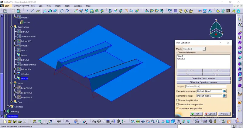
Provide fillets on B surface-
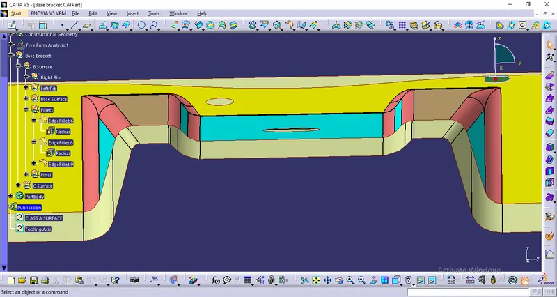
- Add the thickness 2.5 mm to fillet radius of A surface to get the outside fillets radius of B surface.
- Substact thickness 2.5 mm from fillet radius of A surface to get the inside fillets radius of B surface
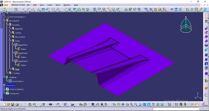
- This is importatant to get the unifrom thickness, which further assures that part will not have any plastic deffetcs.
4. Creating Class C Sufrace
Create boundary about the A surface-
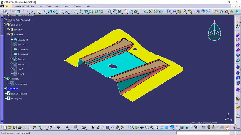
Using the boudary create C surface-
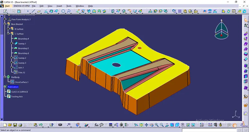
- Make sweep surface using the tooling direction with outward draft of 3 degree
- Durig design it is important to consider the draft direction becasue it decides the parting line of mold.
- Outward draft is necessary becasue then only the parting line will be on B surface which is required.
Similarly create holes and join A surface and C surface
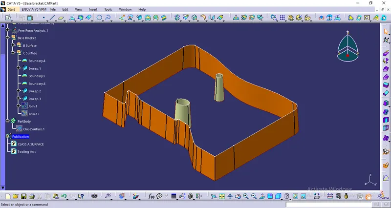
- Publish the class B surface as class C surface for convinience.
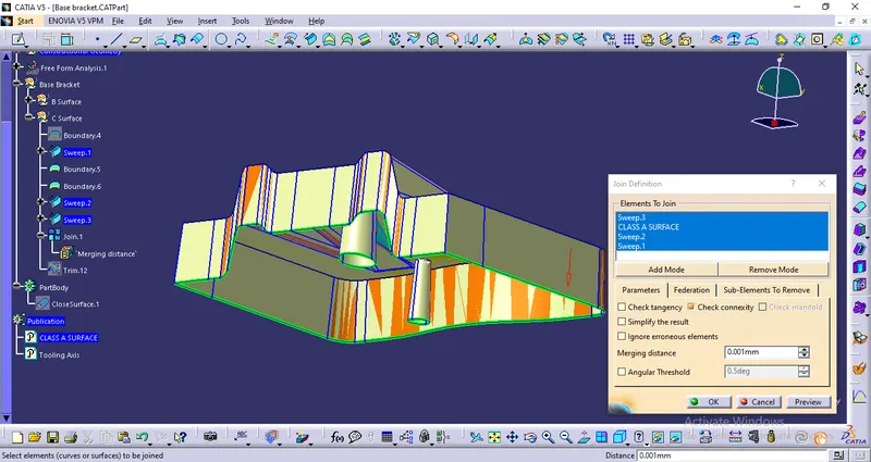
5. Creating solid model
Use all the created A, B and C surfaces-
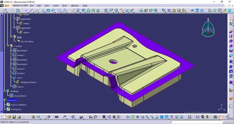
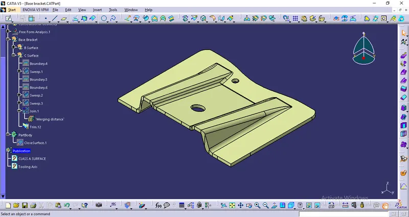
- Trim off the surfaces to get the final surface model
Create the solid model using the final surface model-
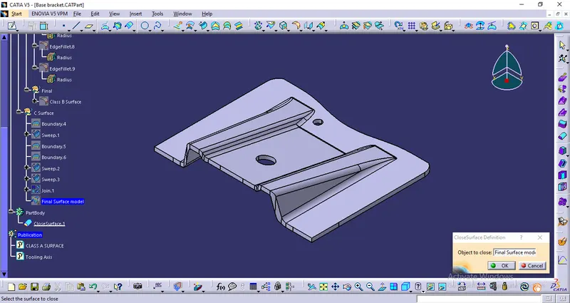
Perfrom draft analysis on the Solid model-
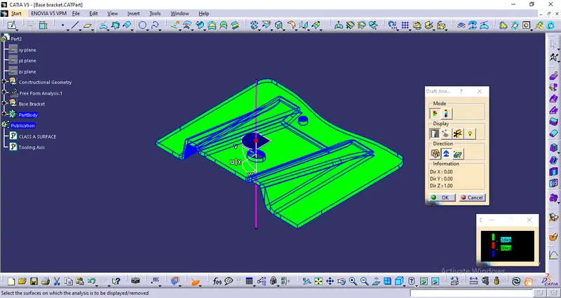
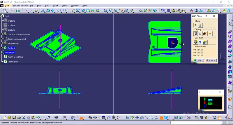
- A and C surface should always be in same colour during draft analysis regardless of the pulling direction
As the model lies in green zone in the draft analysis which suggests that all faces have minimum 3 degree draft angle, which further makes the part manufacturable.