Week 8 - Challenge 2 - Base Bracket Design
AIM:
Create the Base Bracket Plastic component through the given Class-A surface. And perform the Draft analysis on the model.
OBJECTIVES:
To model a base bracket and perform draft analysis on the model.
INTRODUCTION:
CLASS-A SURFACE: a surface made by the designer which is given as an input to the plastic modeler to work on. It is aesthetic surface and the outer most surface.
CLASS-B SURFACE: a surface below a certain thickness from the class-A surface is class-B surface. This is the surface that contains engineering aspects of a model.
CLASS-C SURFACE: a surface that joins class-A and class-B surfaces is class-C surface.
Procedure:
Step-1:
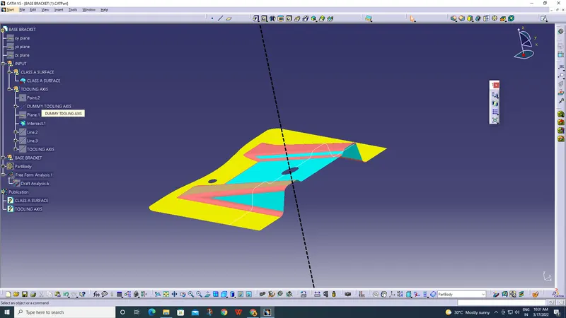
- Create an axis for the component for which the component should move in tooling axis.
- For that, take an axis system and make intersection to corresponding plane.
- Then make a bisecting line to that intersection and make that line as your tooling axis.
- From that tooling axis, we're gonna make 'Class-B' & 'C Surfaces'.
Step-2:
- After taking your tooling axis, take the 'Class-A' Surface as the refrence to make 'Class-B' Surface.
- First take a 'Geometrical Set' and rename it as 'Class-B Surface' and work it from there.
- Then divide the Class-A into simpler geometry. First take the two ribs and work on it.
Step-3:
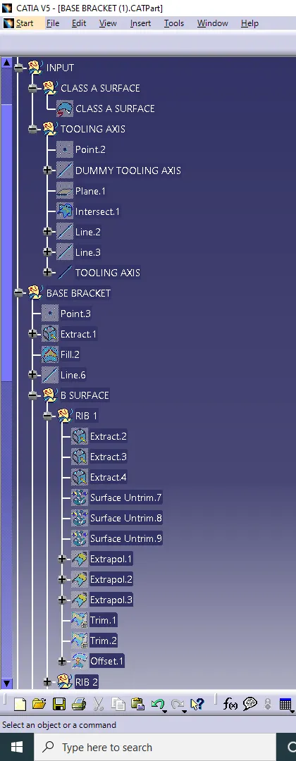
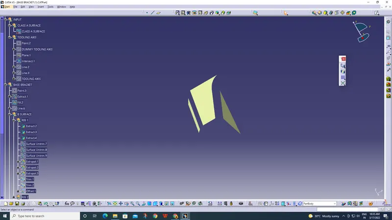
On the first rib, Extract the three surfaces which acts as a rib.
Step-4:
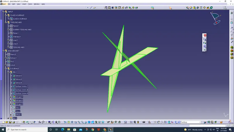
After Extracting, Untrim the surfaces and extrapolate it with point continuity.
Step-5:
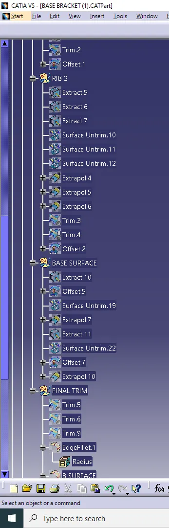
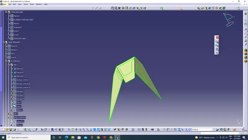
Trim those extrapolates and make it as a single component (rib).
Step-6:
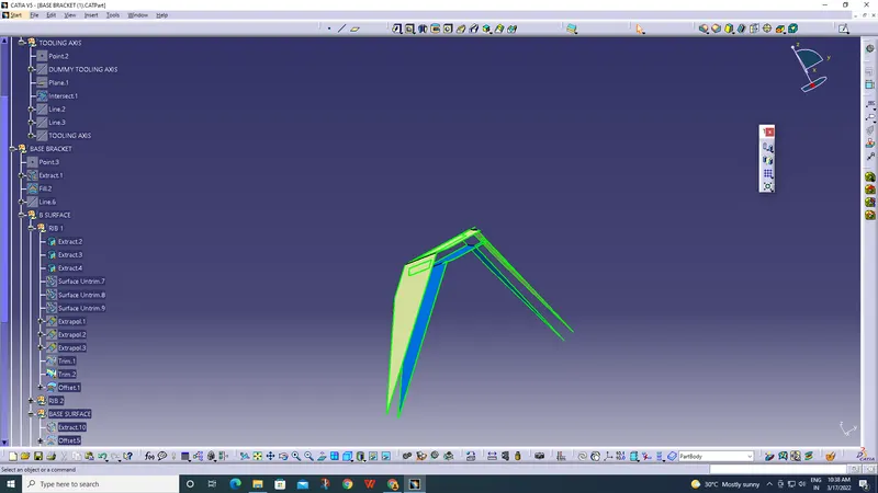
- Make an offset to the trimmed component (rib) of 2.5mm downwards.
- Do the same process for another rib, slope surface and base surface also.
Step-7
Trim those four surfaces and make it as a single component (Class-B).
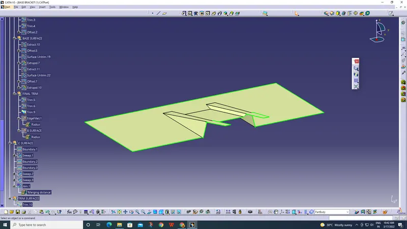
Step-8:
Make fillets to your surface according to your thickness and Class-A Surface.
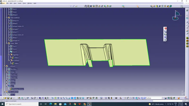
Step-9:
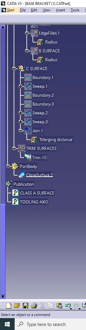
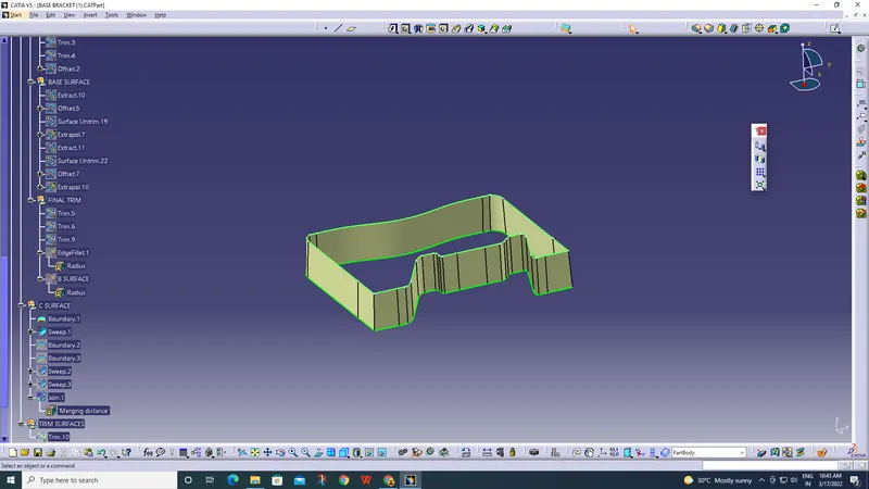
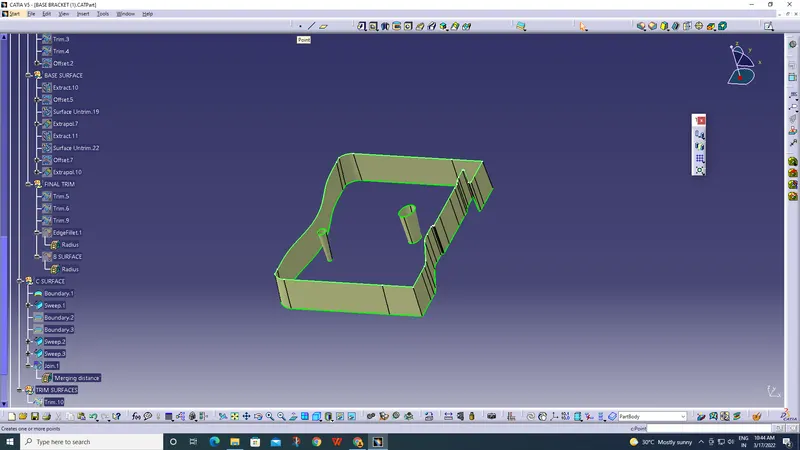
- Next step is to make 'Class-C' Surface from 'Class-A'.
- Take boundary to your 'Class-A' & sweep the curve to the draft direction.
- And Make the entire 'Class-A' to the 'Class-C' Surface.
Step-10:
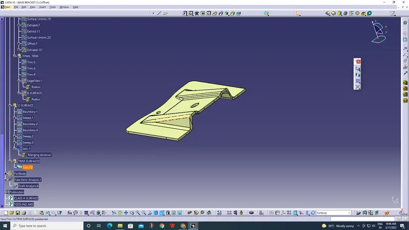
Now, Trim the 'Class-B' & 'Class-C' Surfaces to get a component which joins to your 'Class-A' and makes as a final component.
Step-11:
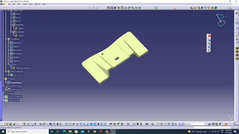
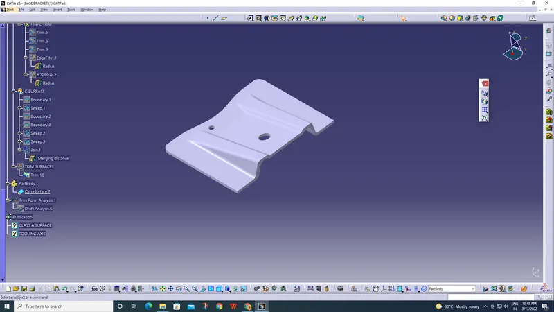
The last step of your component is to make a solid body by going into Part Workbench and doing 'Closed Surface' command. Then you obtain your PartBody.
Step-11:
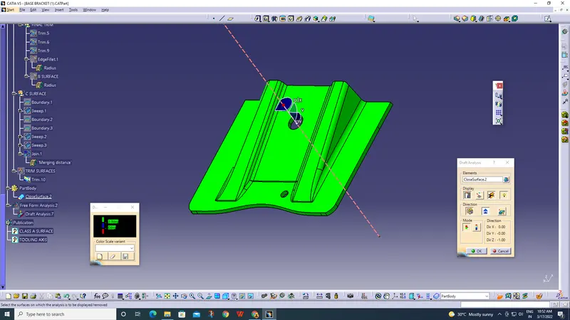
After making it as a complete body, do draft analysis and ensure the body to be manufacturable.
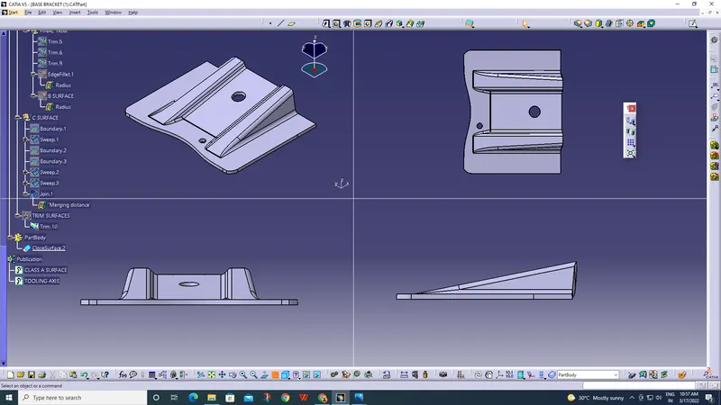
FINAL MODEL VIEWS(ISOMETRIC,FRONT,SIDE,TOP):
TREE STRUCTURE: