Week 8 - Challenge 2 - Base Bracket Design
WEEK-8 CHALLENGE-2
BASE BRACKET DESIGN
AIM
This challenge aims to perform draft analysis for the given surface by defining a tooling direction appropriate to the shape of the surface and also to create the class-B and class-C surfaces.
THEORY
Draft Analysis:
Draft analysis is an operation that is performed to know the draft angles of the surfaces concerning the tooling direction. The minimum feasible draft angle for this design is taken as 3 degrees. Generally for plastic components, a minimum draft angle that can be achieved is 0.5 degrees.
Importance of Draft analysis:
Draft analysis is useful in finding out the design errors concerning the draft angle in the early stage of the design. This reduces the lead time. A good draft analysis features an optimal tooling direction which can improve the cost of production and this also helps the manufacturing team in understanding the design of the component.
PROCEDURE
- CHECK FOR DISCONTINUITY
The first step any design engineer must ensure is the continuity of the surface received. In CATIA this can be verified by two operations: JOIN, BOUNDARY. In some cases, this can also be approved visually. Appropriate steps are to be taken if the surface has any discontinuities.

- DEFINING THE TOOLING DIRECTION
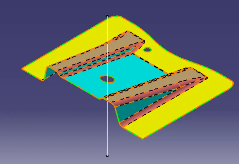
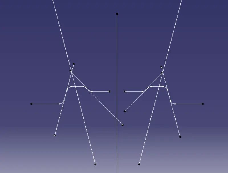
In this step, we define a dummy tooling direction based on the flat surfaces and the holes the surface contains. And the areas which may create some issues when this dummy tooling direction is taken as the main tooling direction and the sketches of these areas should be obtained and concerning those sketches, the main tooling direction has to be obtained.
Dummy tooling direction: Main tooling direction:
- DRAFT ANALYSIS
Draft analysis for the class-A surface is done with the tooling axis obtained and the results are produced.
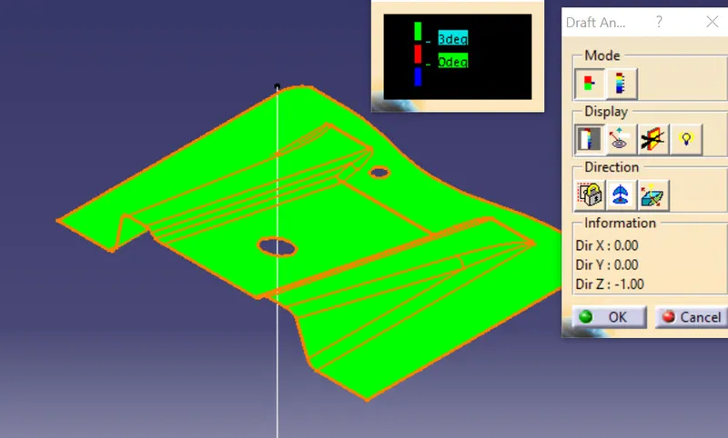
- CREATING THE CLASS-B and C SURFACES
Now with the class-A surface as the parent surface, the B and C surfaces are produced using the operations present in the surface workbench.
- CONVERTING INTO A SOLID BODY
Now the closed surface obtained is converted into a solid body using the operations present in the part workbench.
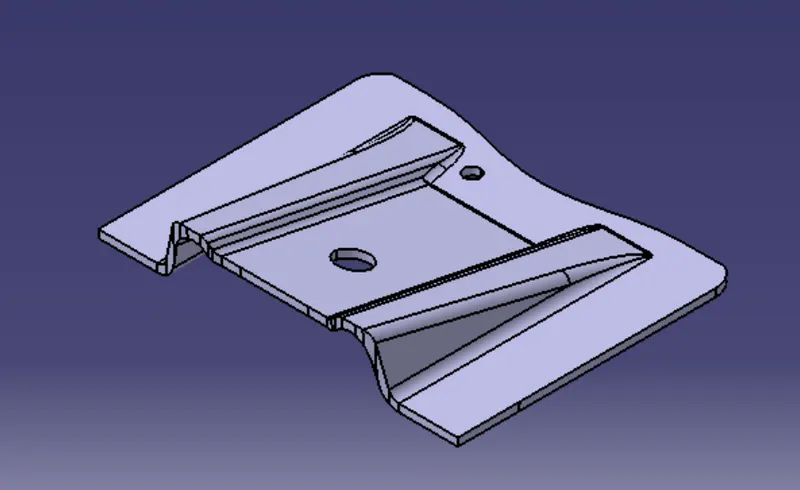
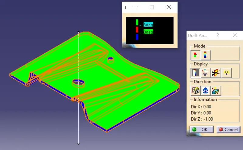
- DRAFT ANALYSIS FOR THE SOLID BODY
In this final step, the draft analysis for the solid body is carried out with the same tooling axis used for class-A.
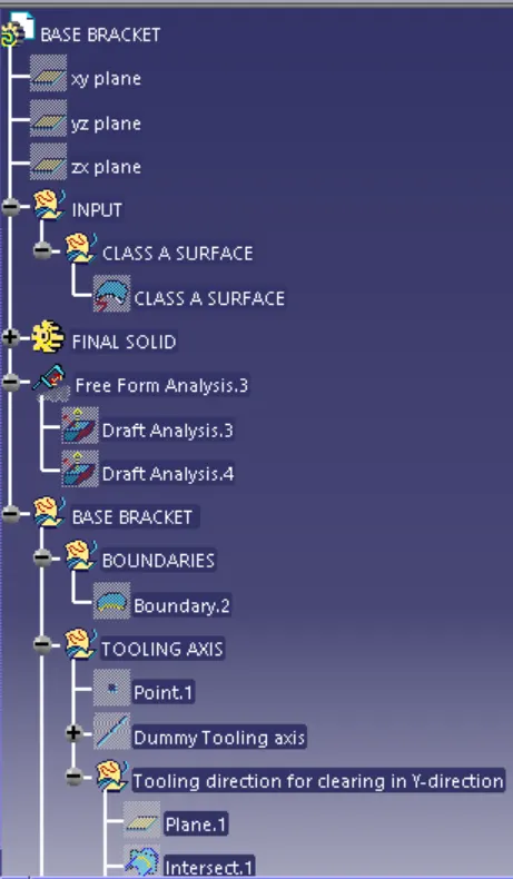
Detailed Tree structure:
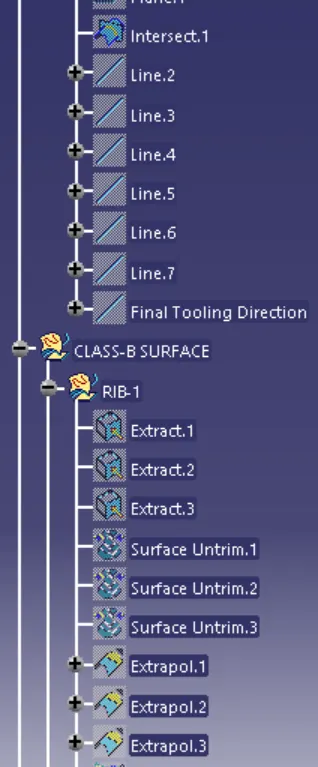
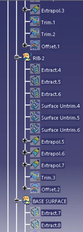
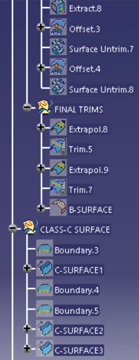
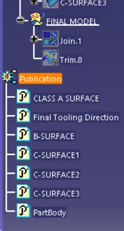
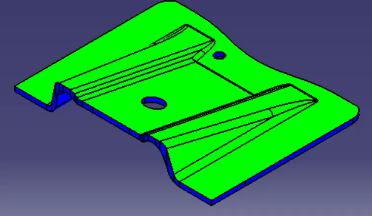
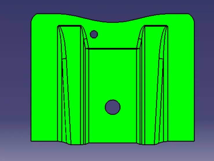
FINAL MODEL
ISOMETRIC VIEW TOP VIEW
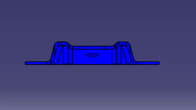
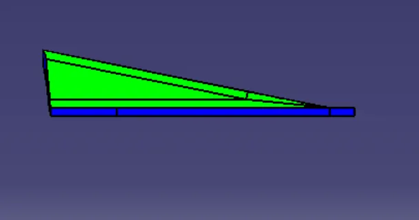
FRONT VIEW SIDE VIEW