Roof challenge
ROOF DESIGN
AIM
The aim of this challenge is to create all the components and test the design conditions from the given skin data of the outer panel and the master sketch.
THEORY/ INTRODUCTION
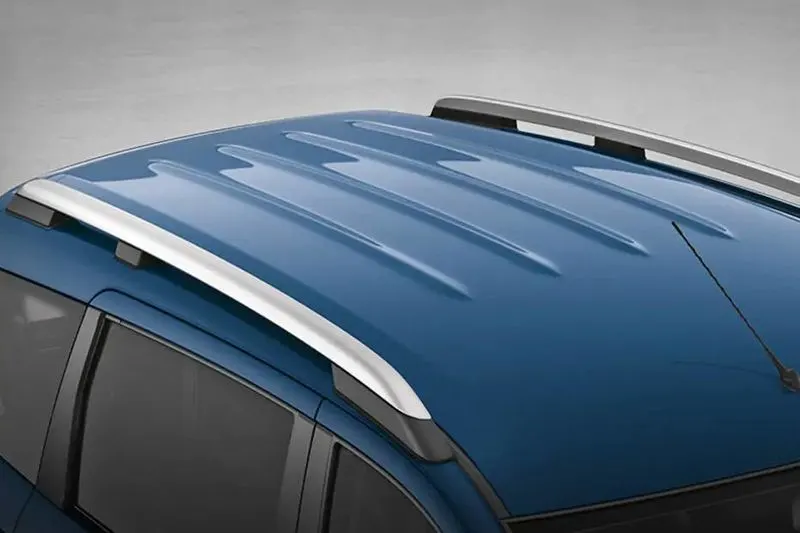
Automobile roof/ Car top is a BIW component that is placed above the passenger compartment to protect the passengers from sun light, rains and other external elements. In some cars roof is also used to place the luggage. There are many types of roofs present in today’s market with different type of cars coming in for different purposes. Some of the common roofs are as follows:
- Sun Roofs
- Moon Roofs
- Panoramic Roofs
- Convertible Roofs
- Hardtops
- Vinyl Roofs .,
IMPORTANT DESIGN CONSIDERATIONS IN DESIGINING A ROOF
1.) Crashworthiness of Roof
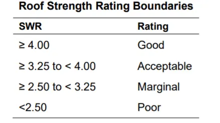
This is a test done on the roof to find the strength-to-weight ratio (SWR) and rate the given car roof. Roof strength evaluations are conducted on a quasi-static test system manufactured by MGA Research Corporation.
The vehicle is adjusted so that:
- The longitudinal centerline of platen is within 10 mm of the initial roof contact point.
2. The yaw angle of the vehicle relative to the longitudinal axis of the platen is 0 ± 0.5 degrees. 3. The midpoint of the platen’s forward edge is 254 ± 10 mm forward of the most forward point of the roof lying on the vehicle’s longitudinal centerline. - The pitch angle of the vehicle matches the on-road angle, while also accounting for any difference between the platen’s pitch angle and the nominal −5 degrees. The maximum combined difference of the vehicle and platen pitch angles from their targets is ± 0.5 degrees.
Once the vehicle is positioned correctly, the roof is crushed to a minimum displacement of 127 mm at a nominal rate of 5 mm/second. The maximum force prior to 127 mm of platen displacement is divided by the measured curb weight to obtain the SWR.
- Heat Distortion Criteria
Generally bodies tend to deform when subjected to change in temperature. So, when we design a roof we need to make sure that the roof is able to withstand the extreme climatic changes which results in temperature change. Heat distortion criteria tell us if the roof is passing this test or not.
- Snow Load Criteria
During extreme snow conditions roof tends to bend or deform with heavy application of the snow load. So, when the load due to the snow is removed the roof should go back to its original shape. To check this condition snow load criteria is used to validate the roof we designed.
PROCEDURE
- FRONT ROOF RAIL
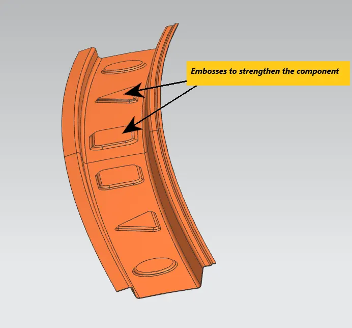
Front roof rail is provided in the roof assembly to strengthen it at the front portion. It is joined to the outer panel by spot welding. Front visibility line criteria and head clearance are considered while designing the front roof rail. Thickness for the front roof rail is maintained at 0.75mm. The extended portion from the outer roof panel and the front/rear roof rail is known as ditch area.
- REAR ROOF RAIL
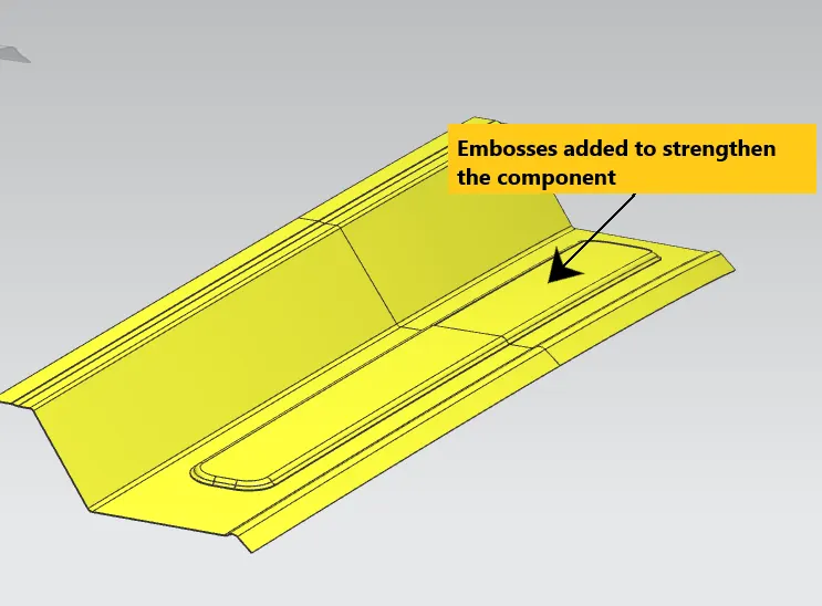
Same considerations that we took for the Front roof rail are taken for rear roof rail i.e., rear visibility line criteria and head clearance for the rear passengers. It will be joined by using spot welding and a minimum length of 15mm has to be provided for this tooling purpose and space for C-pillar has to be accommodated in this rear roof rail (40-50mm) as well. Thickness is same as that of the front roof rail.
- BOW ROOF 1
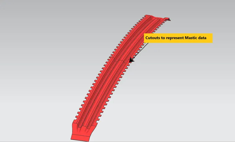
The strength of the roof over its span excluding the front and rear is provided using bow roofs and center roof rail. Bow roof strengthens the assembly locally. Bow roofs are important to achieve the functionality of the roof. Bow roofs are joined to the outer panel using mastic sealants and a 5mm clearance for this purpose has to be provided. Mastics are used because they do not damage the aesthetics of the roof while joining and they also help in reducing the vibrations and noise. Bow roofs are also joined to body side of the roof using spot welding. Thickness of this component is 0.75mm
- BOW ROOF 2
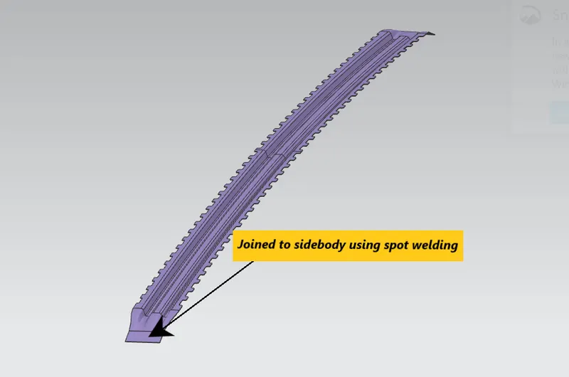
Similar to the bow roof 1 the purpose is same but the position where this bow roof is placed will vary and the structure can be the same or different from the bow roof 1 based on the designer. Same thickness is maintained as that of the first bow roof.
- CENTER ROOF RAIL
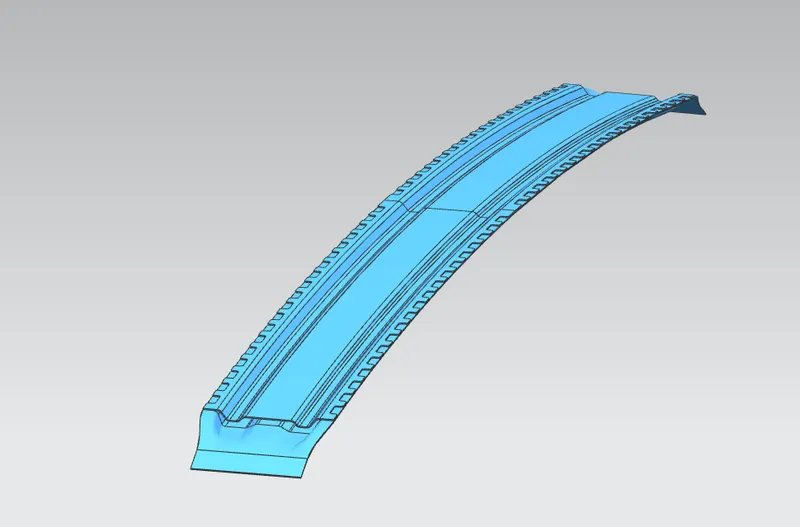
Center roof rail/ Reinforcement rail is usually placed between the bow roofs and for the same purpose as the bow roofs to strengthen the component locally. In some cases this is joined to the outer panel and in some cases it isn’t. The thickness is same i.e, 0.75mm. It is joined to the outer panel through mastic sealants and body side using spot welding.
Eligibility Criteria
Now that we have created all the components we move on to study whether the assembly is eligible or not by performing the heat distortion and snow load criteria.
- For Heat Distortion
Bow-Roof prediction formula:
W= [1.73 x 10^(-3) x L] + [1.85 x 10^(-8) x (R^2)/t] + [1.10 x 10^(-3) x l] – 2.68
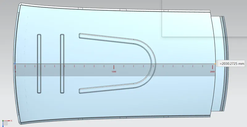
Where, L = Roof length in x-direction (0-Y)
Roof Curvature, R = 2 x (Rx.Ry)/[Rx + Ry]
t= Roof plate thickness
l = Bow roof span
Judgment condition: W< 2.7
1.MEASURING L
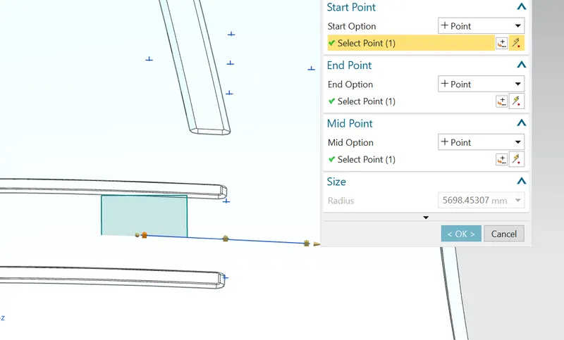
2. MEASURING Rx
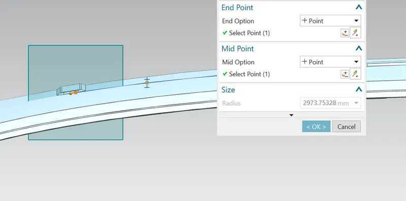
3. MEASURING Ry
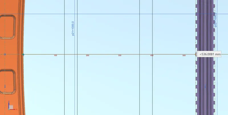
4. MEASURING l
|
S.No |
BOWs |
Rx (mm) |
Ry (mm) |
R (mm) |
l (mm) |
L (mm) |
t (mm) |
R^2/t (mm) |
W |
OK/NG |
|
1 |
FR&1ST |
5698.45307 |
2973.75328 |
3908.14026 |
536.0 |
2030.2725 |
0.75 |
20364747.056 |
1.8 |
OK |
|
2 |
1ST&CTR |
4724.16741 |
7196.13545 |
5703.83973 |
364.1 |
2030.2725 |
0.75 |
43378383.554 |
2.04 |
OK |
|
3 |
CTR&2ND |
3910.97091 |
10923.1401 |
5759.70924 |
364.6 |
2030.2725 |
0.75 |
44232334.040 |
2.05 |
OK |
|
4 |
2ND&RR |
3208.67879 |
15064.3886 |
5290.49481 |
393.7 |
2030.2725 |
0.75 |
37319113.780 |
1.96 |
OK |
So, from the table we get that for this position of roof rails it satisfies the heat distortion criteria for all the components. No changes would be required but creating embosses on front and rear roof rails increases strength for the respective components.
- For Snowed Criteria
Snow load prediction formula
Qr = [Iy x (t ^ 2)]/ [α x (s^2) x {([Rx+Ry]/2)^2} x (10^8)]
α= My x Lx^2 x 10^(-12) My= Y(Ly –Y)
t= Roof plate thickness
Ly= Distance between the front and the rear roof rails on the vehicle along 0Y
Lx= Distance between the left and right end of the roof on the BOW
Y= Distance between front roof rail to Roof Bow
S= Distance for which Roof BOW bears divided load
S= (L1+L2)/2
Iy= Geometrical Moment of inertia of Roof Bow
Rx= Roof panel curvature radius of the length Lx in Front view
Ry= Roof panel curvature radius of the length s in side view
Judgment condition: Qr>= 3.1
1. MEASURING Lx

2. MEASURING Ly
Ly in this case is same as L in Heat distortion i.e, Ly=L= 2030.2725mm
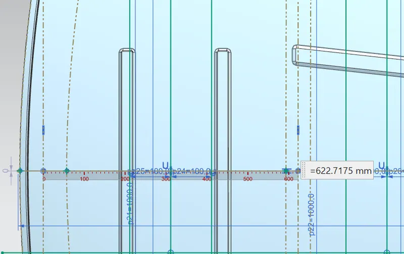
3. MEASURING y
4. MEASURING Rx
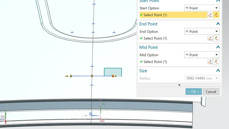
5. MEASURING Ry
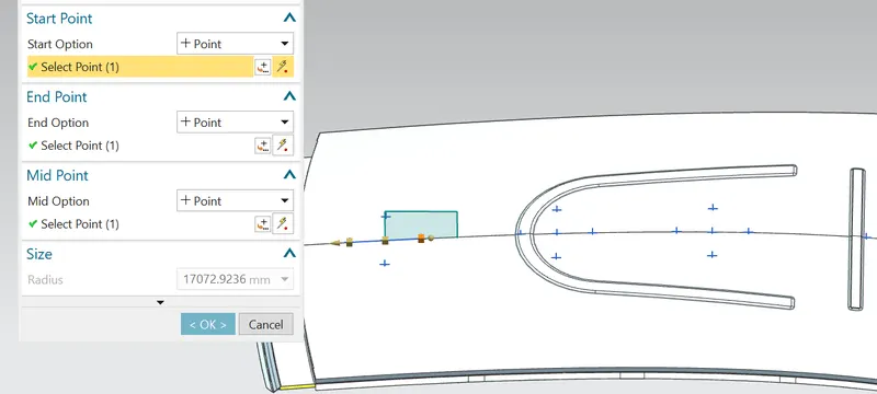
|
S.No |
BOWs |
Iy (mm^4) |
α (mm^4) |
Lx (mm) |
Ly (mm) |
y (mm) |
s (mm) |
Rx (mm) |
Ry (mm) |
t (mm) |
Qr |
OK/NG |
|
1 |
FR&1ST |
843.0 |
1.123 |
1132.1 |
2030.2725 |
622.7 |
528.45 |
4290.31854 |
4989.67780 |
0.75 |
1.86 |
NG |
|
2 |
1ST&CTR |
2589.7 |
0.811 |
1082.0 |
2030.2725 |
434.2 |
434.17 |
3844.59325 |
7165.76164 |
0.75 |
6.83 |
OK |
|
3 |
CTR&2ND |
823.3 |
0.778 |
1060.1 |
2030.2725 |
434.14 |
476.92 |
4303.32392 |
11505.1411 |
0.75 |
1.00 |
NG |
|
4 |
2ND&RR |
0.860 |
1046.1 |
2030.2725 |
519.7 |
3882.14483 |
17072.9236 |
0.75 |
6. MEASURING s
|
BOWs |
L1 |
L2 |
S |
|
FR&1ST |
622.7 |
434.2 |
528.45 |
|
1ST&CTR |
434.2 |
434.14 |
434.17 |
|
CTR&2ND |
434.14 |
519.7 |
476.92 |
|
2ND&RR |
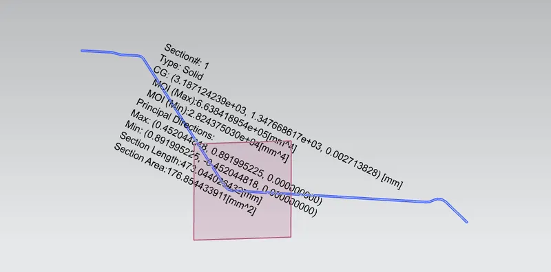
7. MEASURING Iy
1.) Front roof rail 2.) Bow roof-1
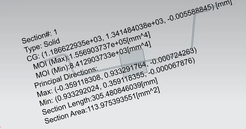
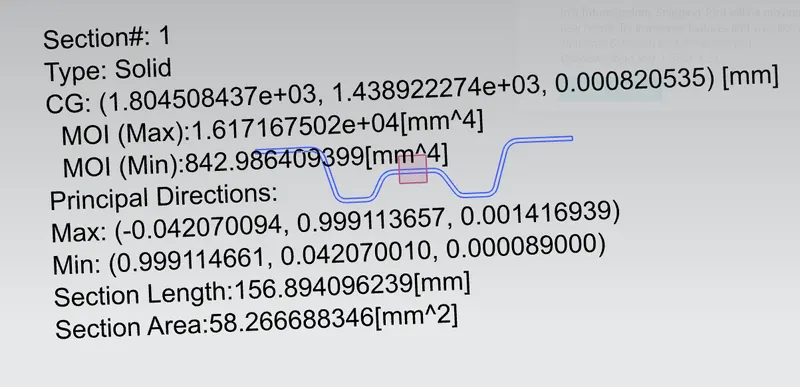
3.) Bow roof-2 4.) Center roof rail
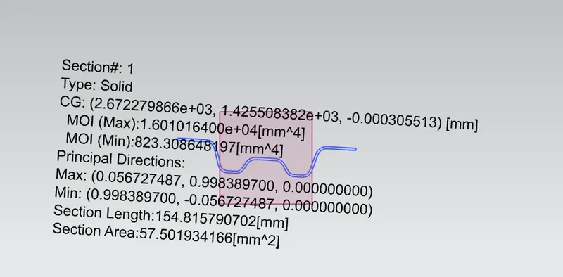
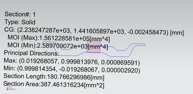
5.) Rear roof rail
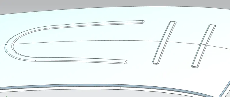
For Snow load we got that the part is failing between front roof rail and BOW roof 1 and between center roof rail and BOW roof 2.
Now to improve the part we have two solutions:
- Strengthen the outer panel by creating embosses in the regions where the part is failing
- By repositioning the roof rails and increasing the moment of inertia.
Since the second one is more time consuming than the first one, we prefer the first method. If the manufacturer do not want embosses on the outer panel second method should be followed.
Embosses on the outer panel
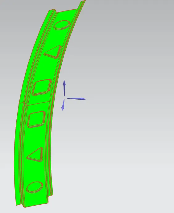
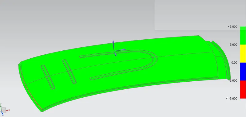
DRAFT ANALYSIS
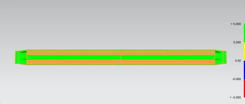
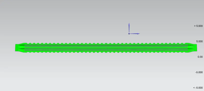
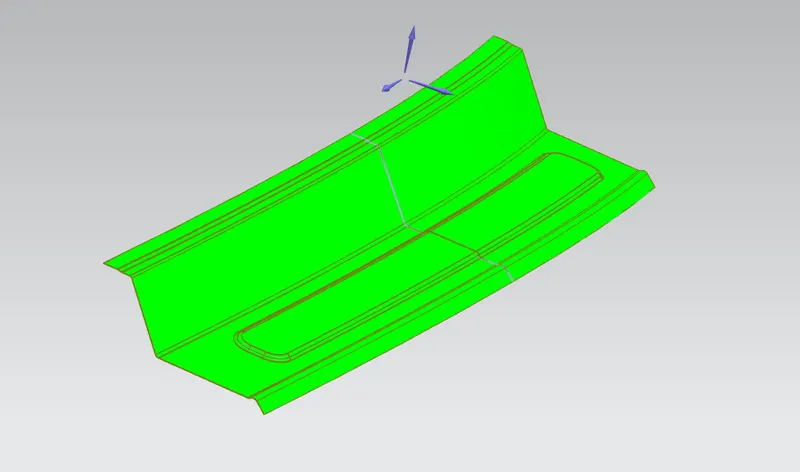
Draft analysis needs to be done for the part after all the design is completed to know whether the part is producible by deep drawing. There should always be a positive draft for the part to be producible. For sheet metal the draft angle is taken as 7 degree and sometimes around 5 degree is also accepted.
1.) Front roof rail 2.) Center roof rail
3.) Bow roof - 1,2
4.) Rear roof rail 5.) Roof Outer panel
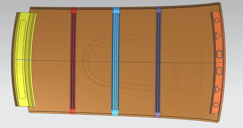
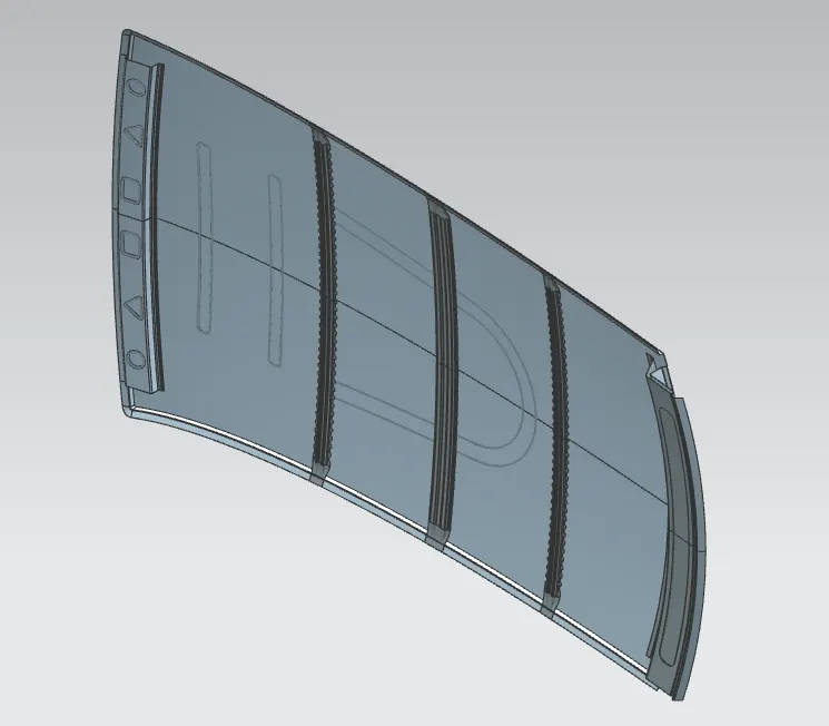
ROOF ASSEMBLY
CONCLUSION
A final roof assembly is made with all the necessary components and calculations.