Door Arm Rest Week 8 Challenge
DOOR ARM REST
Defining Tooling Axis
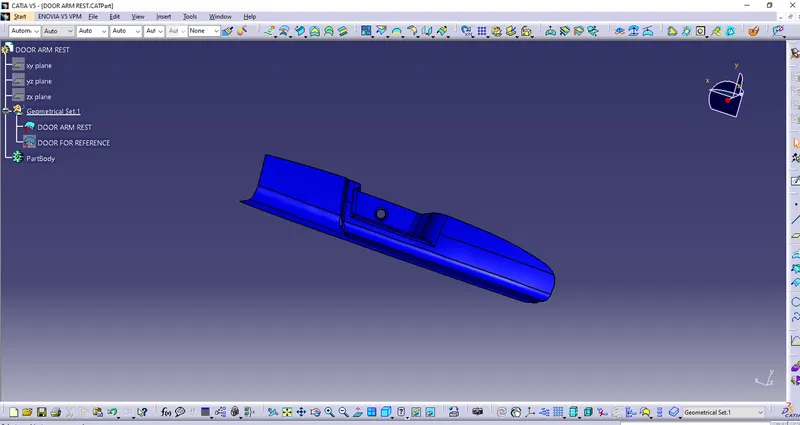
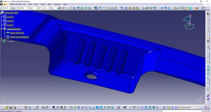
At first I have opened the Part and under the Geometrical Set.1 there are two Surfaces.One of them is a CLASS A SURFACE that I need - DOOR ARM REST ,that I have given in Show mode.After detailed examination of the given Surfaces I have decided to put a Tooling Axis in the hole as shown bellow.
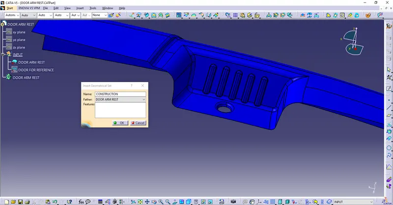
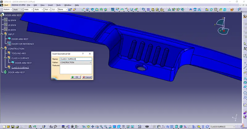
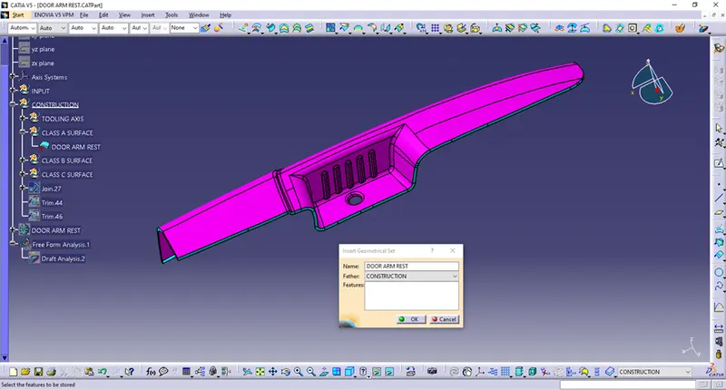
I have inserted a Geometrical Set CONSTRUCTION and under it Geometrical set TOOLING AXIS,CLASS A SURFACE (there I have copied DOOR ARM REST Surface from INPUT (so I have renamed given Geometrical Set),CLASS B SURFACE and CLASS C SURFACE.
It can be seen from various angles that Surface is flexed from one side to another and here we are dealing with multiple fillets that continue one to another and at the end - the hole is also excentric,the hole boundary is not a circle than some curve devided in two curves.
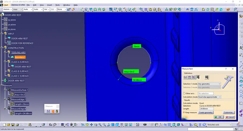
Here can be seen excentricity of the hole – view normal to bottom surface.
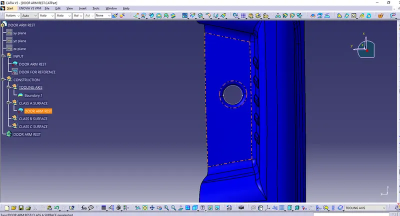

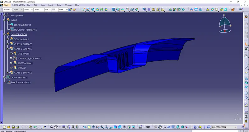
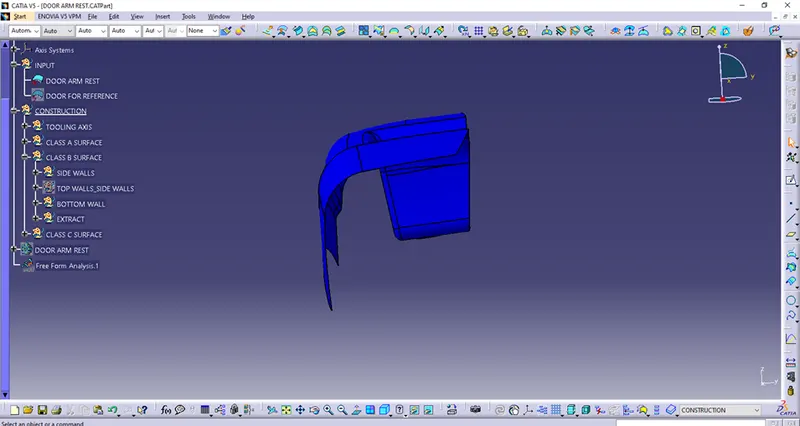
So, I decided to have a point for tooling axis in the center of the 26mm radius.
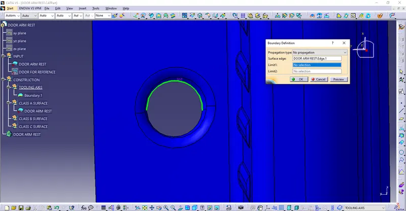
Point for tooling axis is inserted as shown bellow,in the line/center middle.
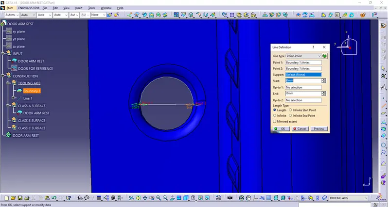
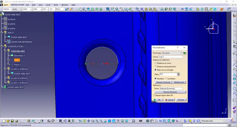
Then in that point I have inserted Axis system as follows.
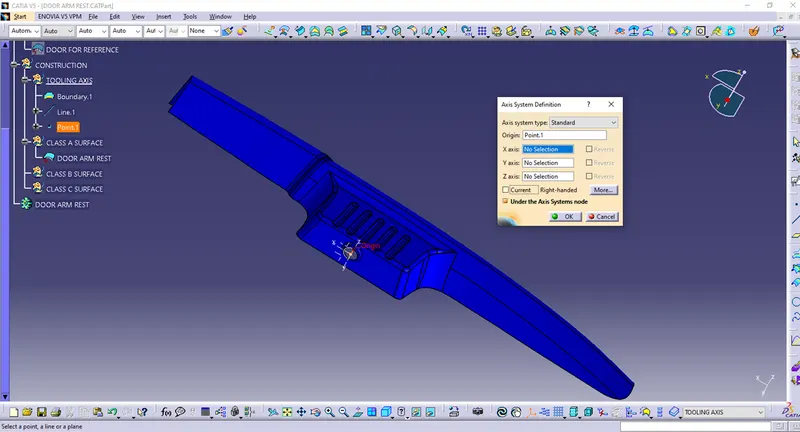
I have to say,afterwards I have tried various solutions with TOOLING AXIS X DIRECTION and TOOLING AXIS Y DIRECTION but the solutions after Draft Analysis was always unsatisfactory,then I have exclude those solutions.
So defined Tooling Axis as given bellow – gives unsatisfactory Drafts.
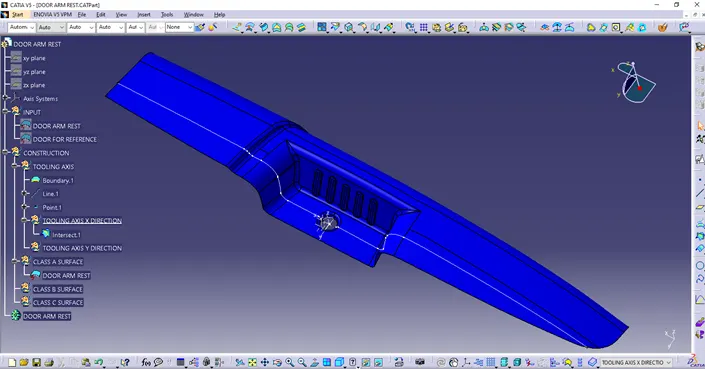
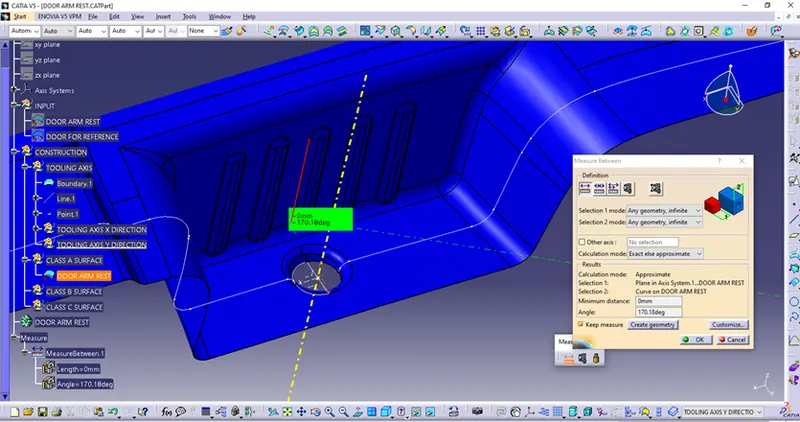
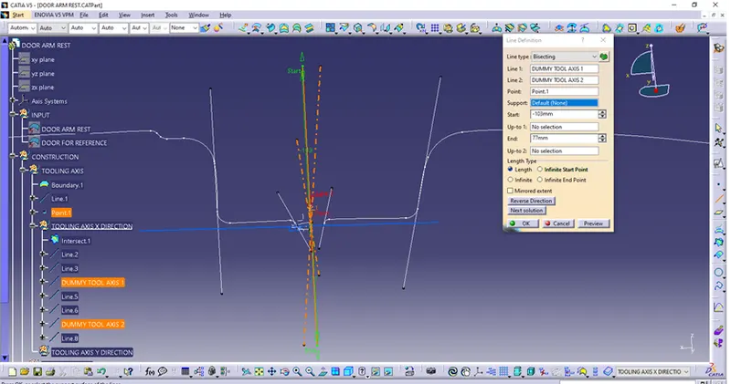
Examples shown above are furhtermore not taken in consideration,because it gives unsatisfactory solutions.
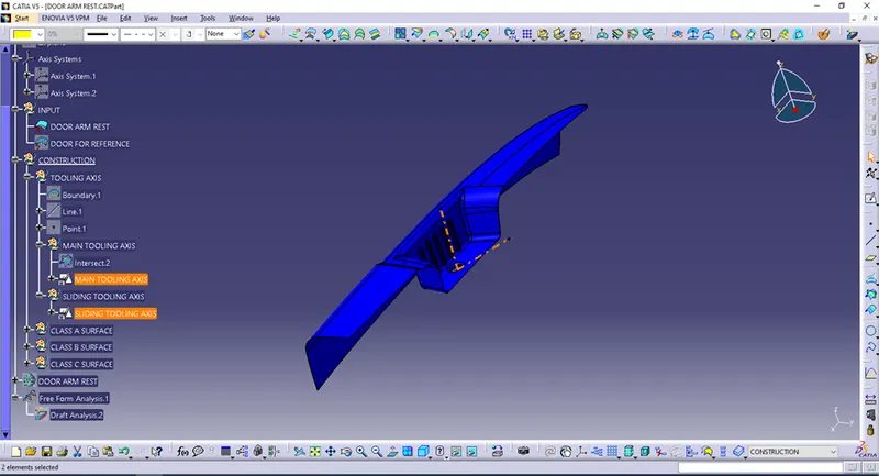
So,after so many tries to reach a 3deg angle in all directions of the flexed and so filleted CLASS A SURFACE I made solutions with two Tooling Axis as follows.Under the Geometrical Set TOOLING AXIS I have inserted two Geometrical Sets – MAIN TOOLING AXIS and SIDE TOOLING AXIS.
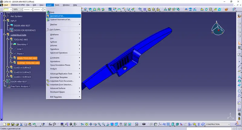
Then under the Geometrical Set MAIN TOOLING AXIS I have made intersection and Positioned Sketch (Sketch I renamed as MAIN TOOLING AXIS).
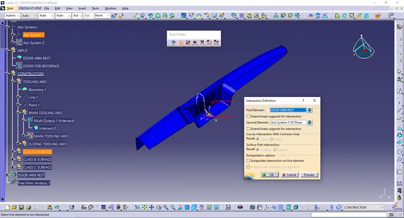
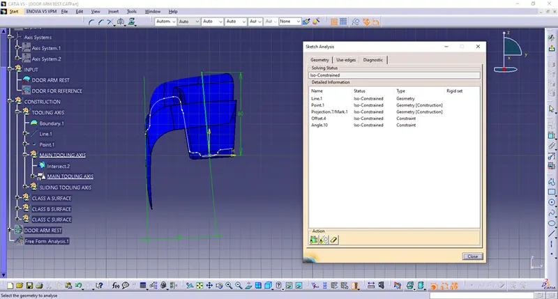
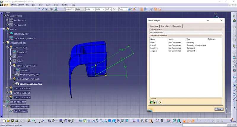
Under SLIDING TOOLING AXIS I made a sketch as follows (I renamed it as SLIDING TOOLING AXIS). That will be my second direction of moving Core/Cavity Part in Mold assembly.Two directions of Tooling Axis gives a satisfactory solution in order to get a manufacturable part with at least 3deg draft.
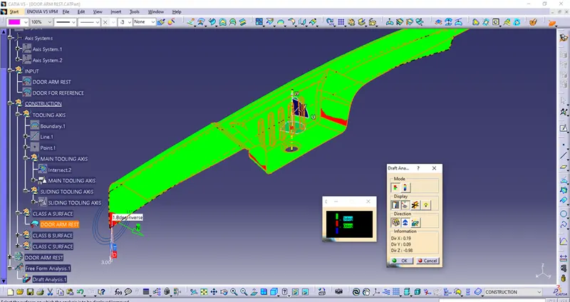
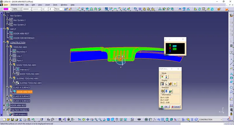
DRAFT ANALYSIS of the CLASS A SURFACE for TOOLING AXIS –
MAIN TOOLING AXIS and SIDE TOOLING AXIS shows results as bellow.
On those pictures we can see some red areas and that is why I needed second direction for extrusion so bended and filleted surfaces.On the end that is satisfactory solution with a draft 3deg or more and part is regarding drafts manufacturable.
CLASS B SURFACE
Now I am going to make CLASS B SURFACE on the basis of CLASS A SURFACE.At first under already inserted Geometrical Set CLASS B SURFACE I am inserted Geometrical Sets SIDE WALLS,TOP WALLS_SIDE WALLS, BOTTOM WALL (and furthermore EXTRACT,during work on given Surfaces).
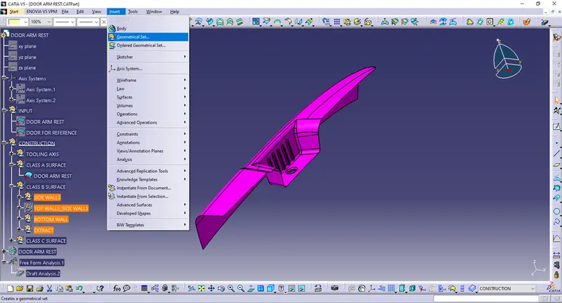
Under the Geometrical Set SIDE WALLS I have extracted following surfaces.
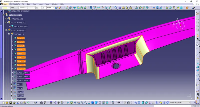
Then I untrimed those fillets to see their value.
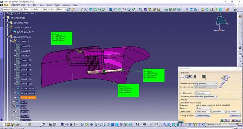
Then I have joined those extracted surfaces as follows.
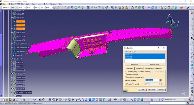
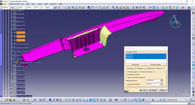
And offseted for a 2.5mm.
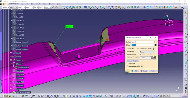
On so offseted surfaces I have made boundaries and extrapolated surfaces as follows.
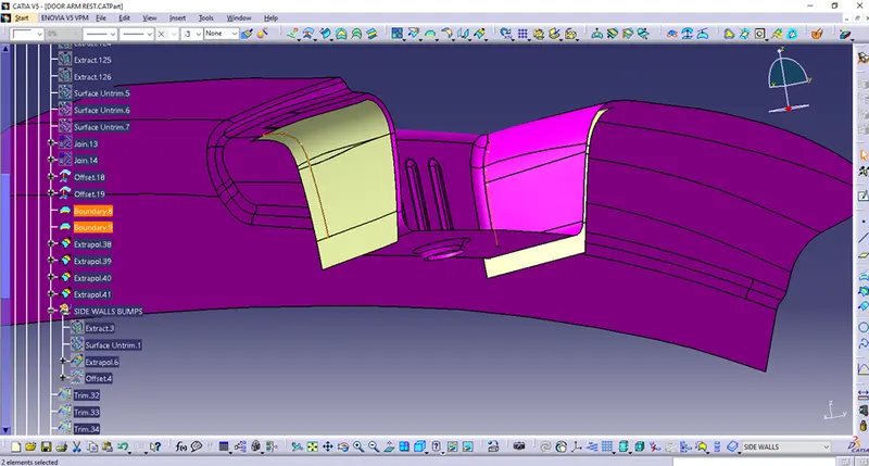
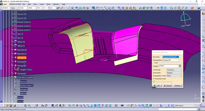
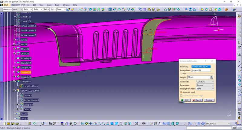
Then in the Geometrical Set SIDE WALLS I have inserted Geometrical Set SIDE WALLS BUMPS where I have extracted,untrimed and offseted surfaces as shown.
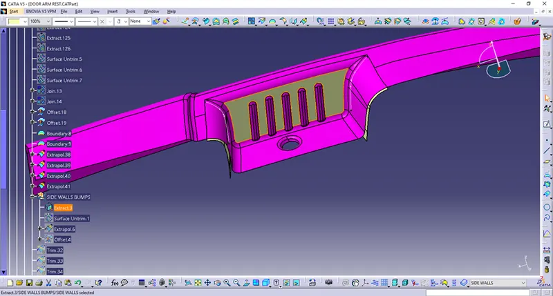
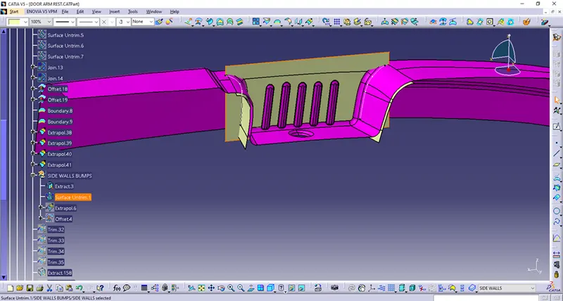
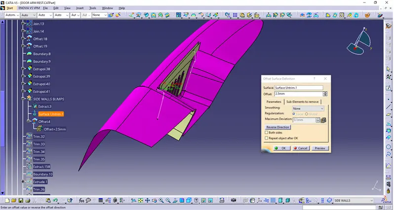
Then,now I am dealing with a BOTTOM WALLS Geometrical Set as before – extract,untrim,extrapolate,offset.
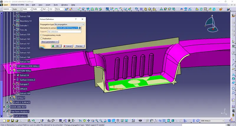
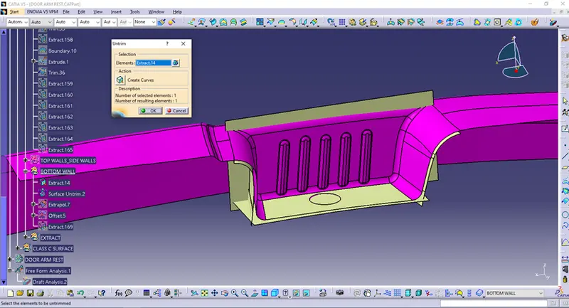
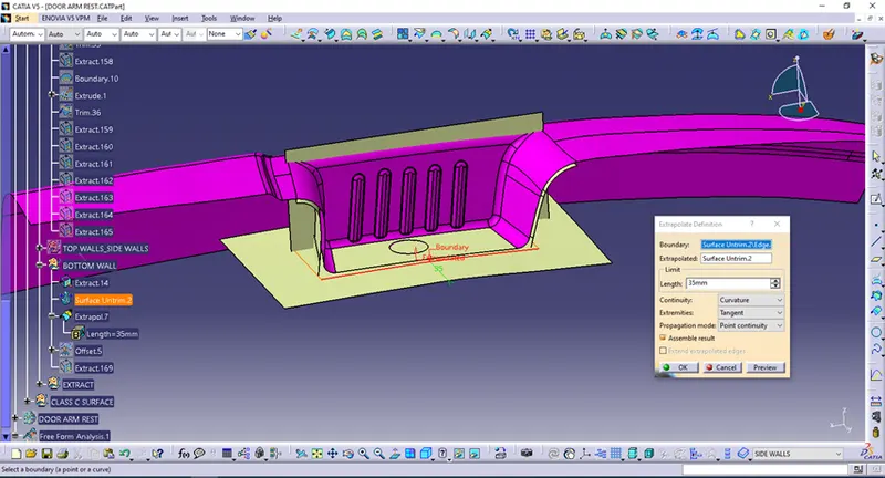
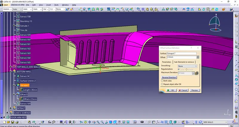
Now I have trimed Side and Bottom surfaces as it is shown in following images.
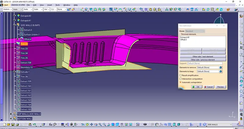
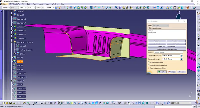
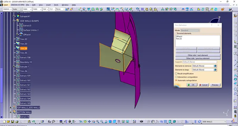
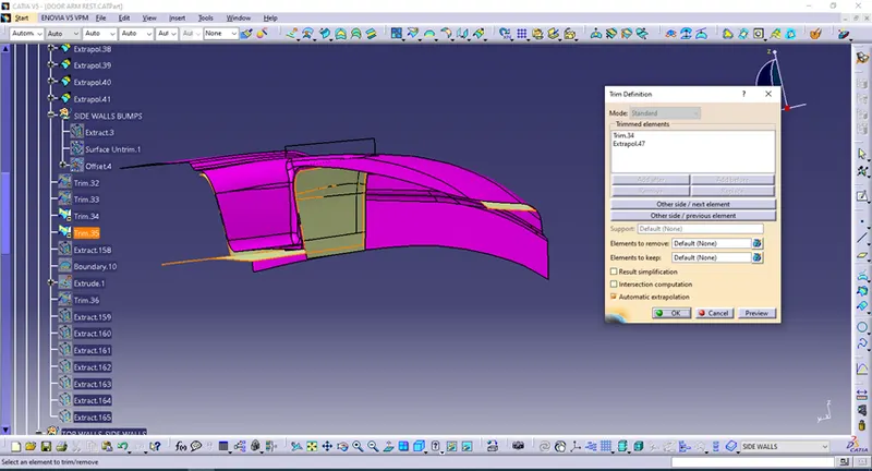

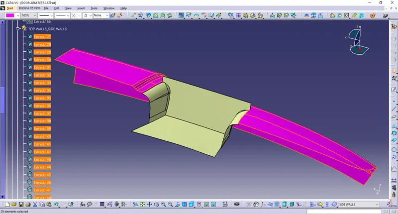
Under the TOP WALLS_SIDE WALLS Geometrical Set I have done following procedure to deal with those fillets and surfaces.First,I have extracted all those surfaces as bellow on the basis of CLASS A SURFACE.
Then I have offseted Extract.153.
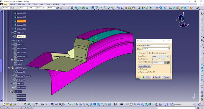
End extrapolated the offset.
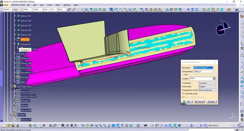
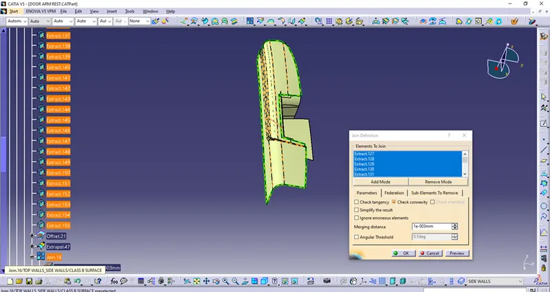
Afterwards I have joined all those extracted surfaces TOP WALLS_SIDE WALLS Geometrical Set’s.
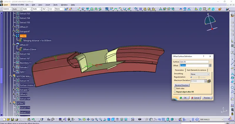
Then,so joined surfaces I have offseted for a 2.5mm inwards,as it is shown on image.
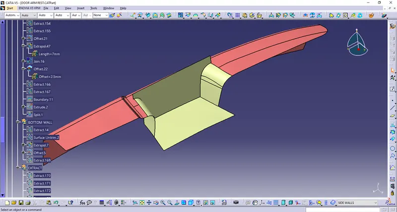
Now,in order to deal with that problematic features, where one surface goes over and the others where is a gap,I have done following steps.
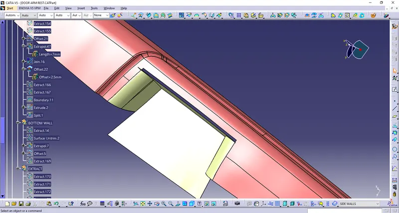
I went back to the SIDE WALLS Geometrical Set and made a trim as shown in image.
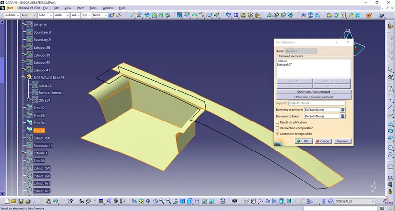
Now to deal with leftovers I have first made extraction of the offseted surface CLASS A SURFACE.
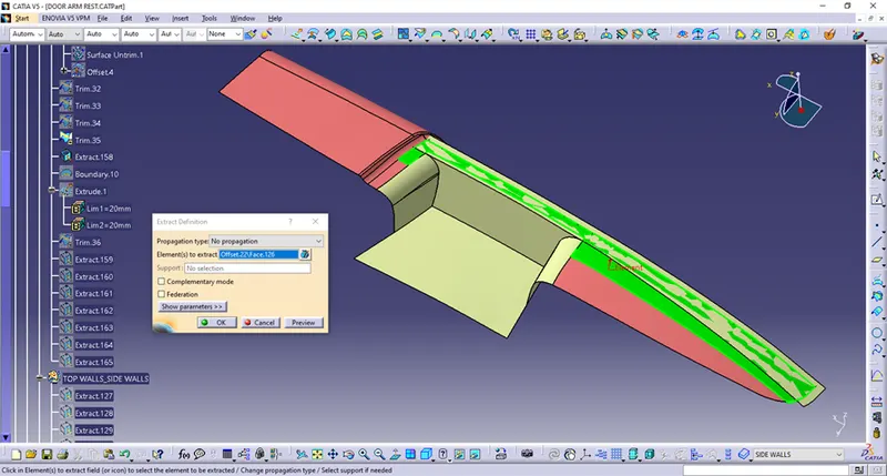
And then I made a boundary of extracted surface as it is shown on image.
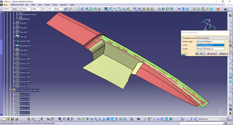
On that basis is made extrude.
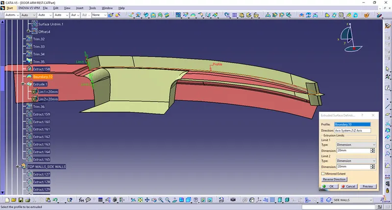
Then I have trimed those surfaces.
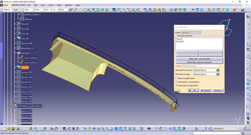
Such trimed surfaces I have extracted as shown left.
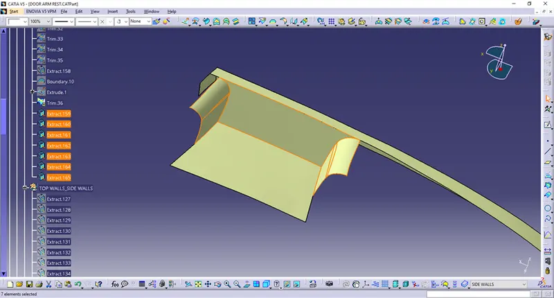
Then I have extracted top surface on the basis Trim.36.
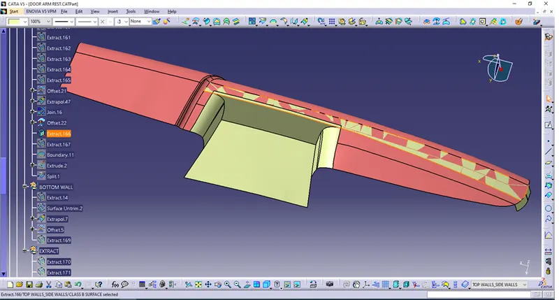
And offseted surface on the basis of CLASS A SURFACE is also extracted.
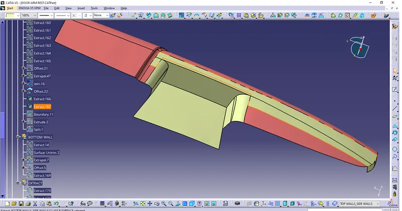
Boundary and extrude are then made on the extruded surface of Trim.36.
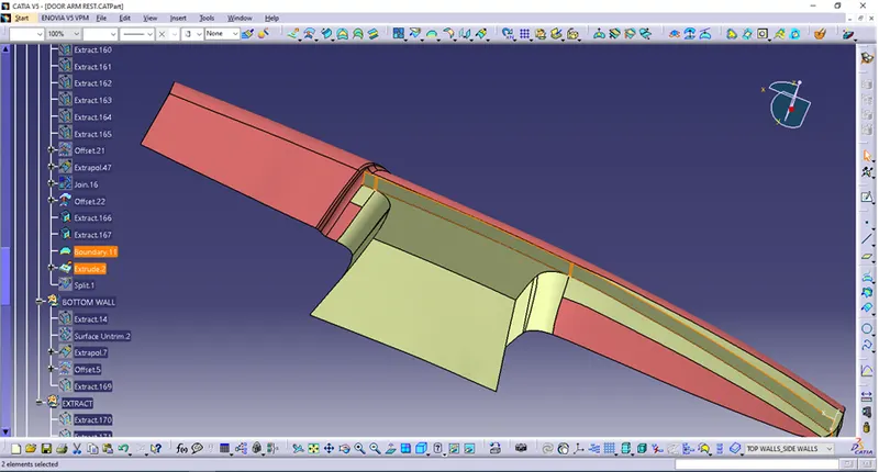
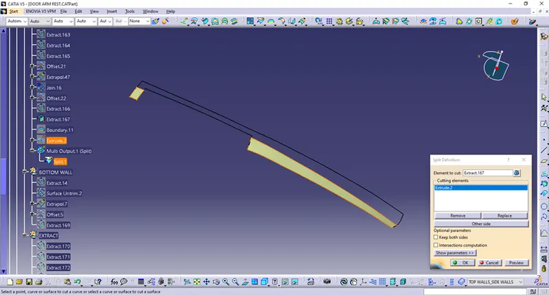
And then it is splited to get the last surfaces that I need to join in one surface – CLASS B SURFACE.
As I have previously said,during work on surfaces I have noticed I will need separate Geometrical Set,where I will copy other extract all required surfaces to make a quality join. Accordingly I have under CLASS B SURFACE inserted Geometrical Set EXTRACT.
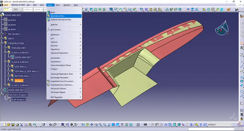
In Geometrical Set EXTRACT I have extracted all surfaces as shown.
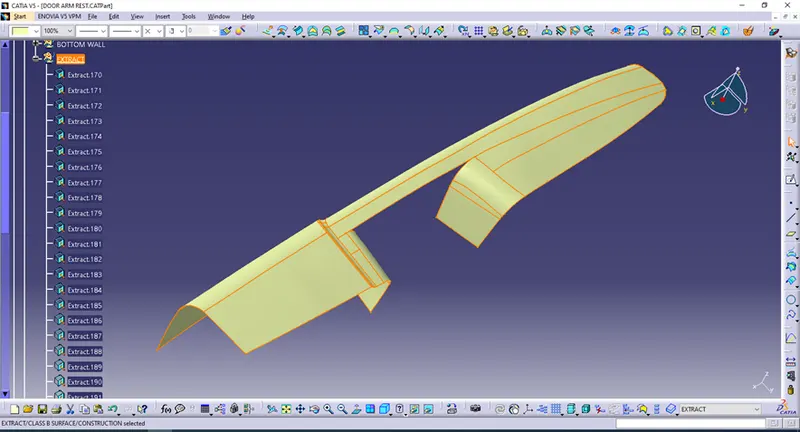
Then I have joined those surfaces.
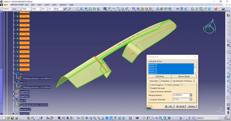
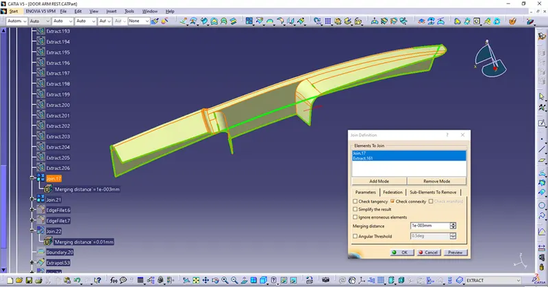
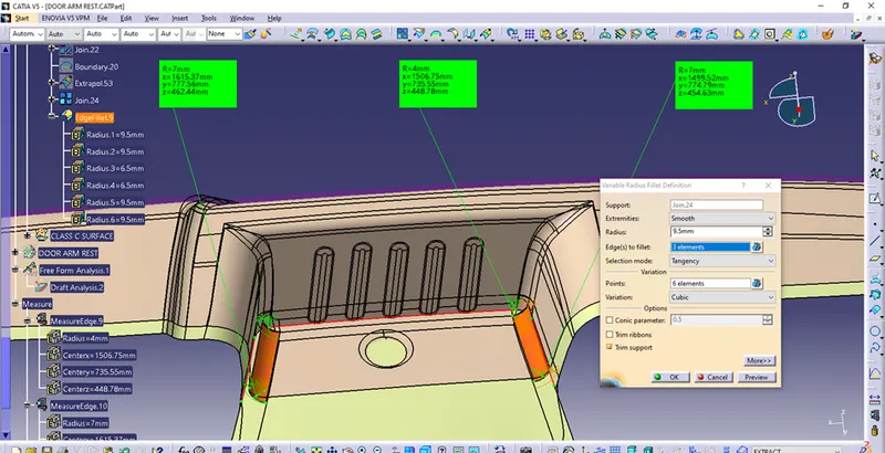
Then I have done filleting in correlation to offset of 2.5mm and if it is made inwards or outwards.
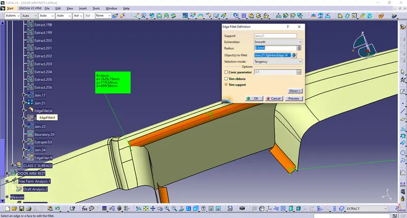
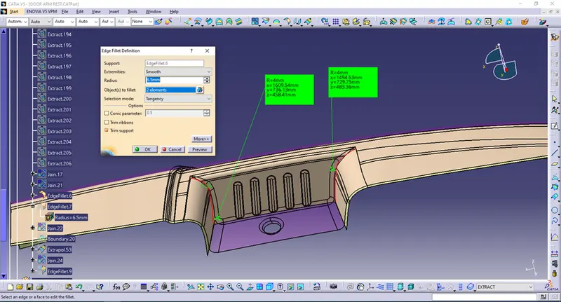
Then in the BOTTOM WALLS Geometrical Set I have extracted offseted and trimed bottom surface.
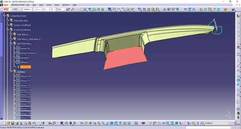
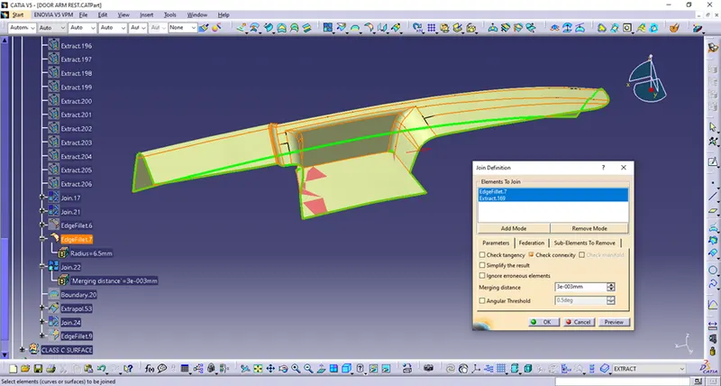
And I have joined those surfaces as shown.
Then I have done boundary on the joined surfaces as on image bellow.
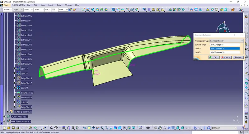
And extrapolate it.
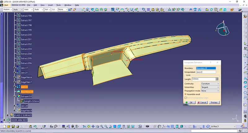
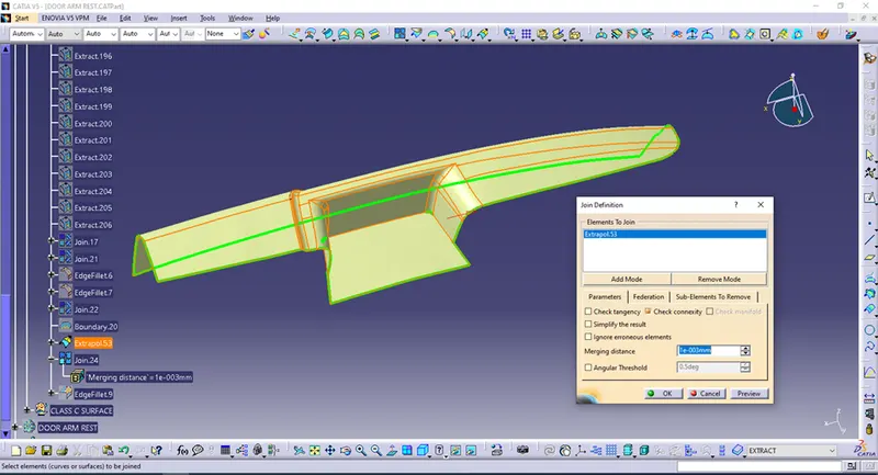
In order to get a smooth surface I have done join once again,merging distance 0.001mm.
At the end I have done filleting regarding offset.
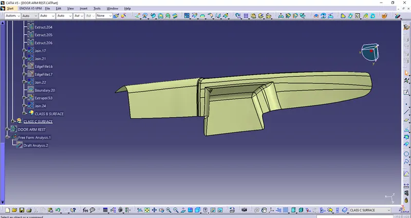
CLASS C SURFACE
Now I am going to construct CLASS C SURFACE.
That is why I have extracted CLASS A SURAFCE and on one boundary of that surface made a sweep as shown bellow.
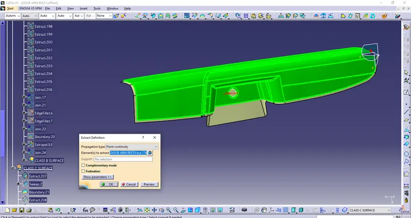
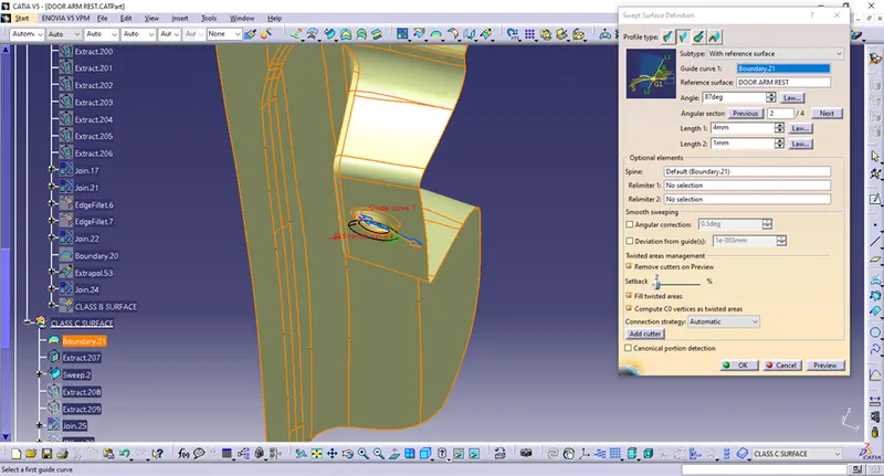
Then I have extracted and joined those surfaces.
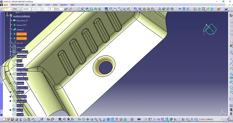
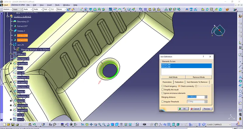
I have offseted join for a 2.5mm and on the boundary of offset I have done extrapolation as shown on images.
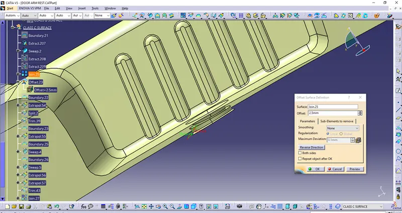
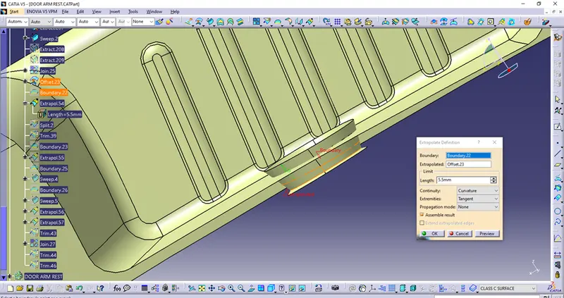
Then I have splited and trimed surfaces to get a proper shape.
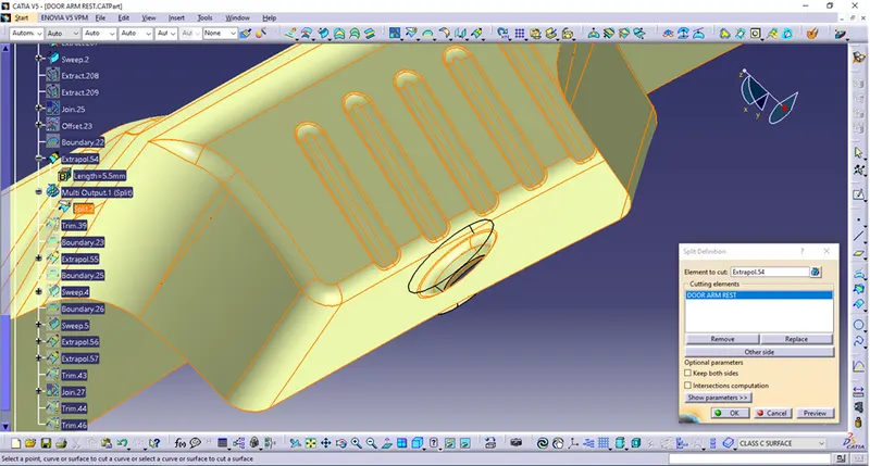
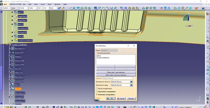
Furthermore on the trim boundary as on the image I have done extrapolation.
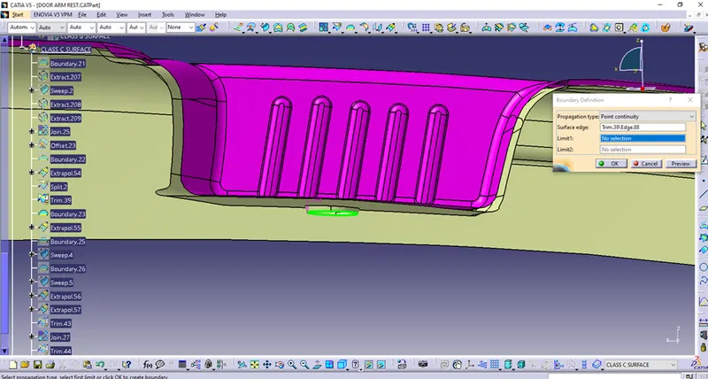
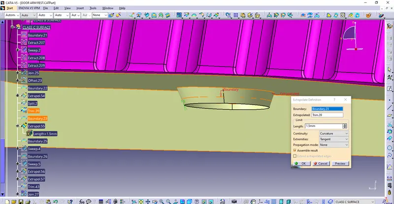
On so defined boundary of the CLASS A SURFACE I have done sweep with a little bigger draft (83deg – that means 7deg outwards) in order to get sufficient draft angle on the complete,complex reference surface.
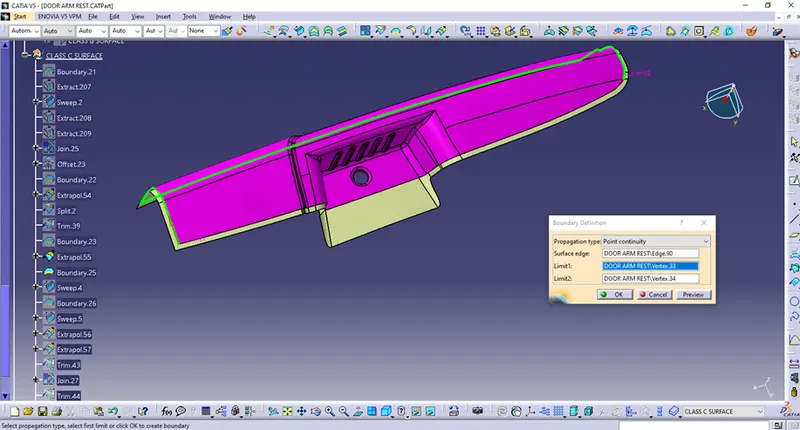
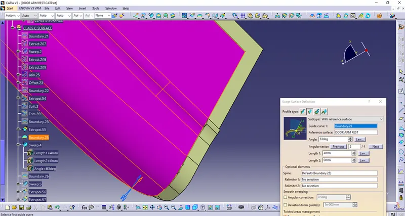
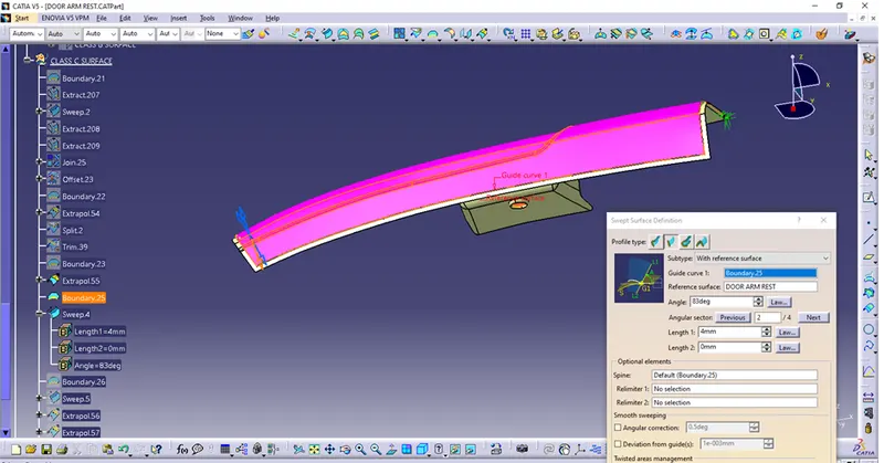
Boundary of the CLASS A SURFACE on the other side is also used for a sweep with a little bigger draft (83deg –7deg outwards).
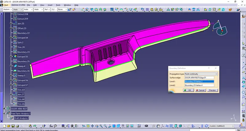
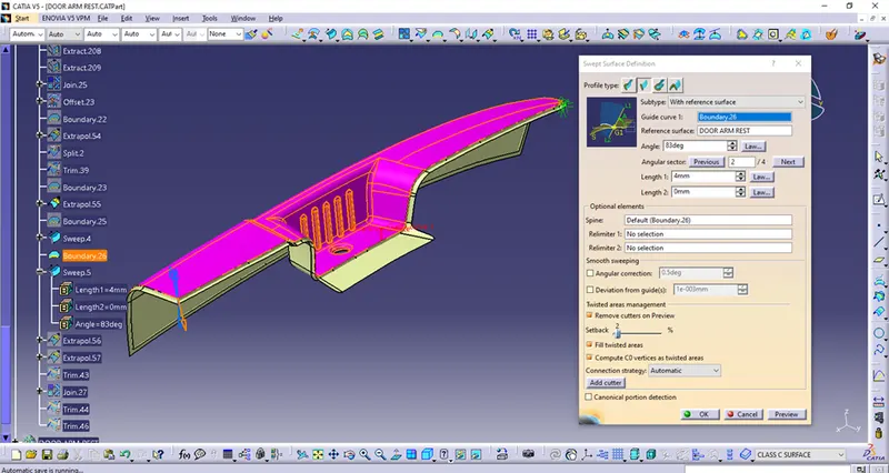
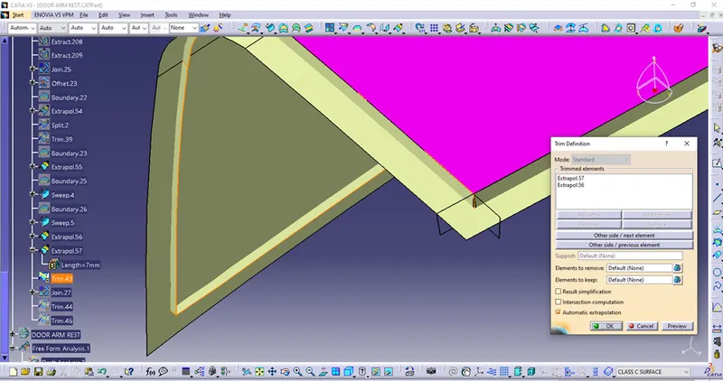
As it can be seen,between those sweeps there is a little gap that should be closed.That is why I have done extrapolation on those edges.
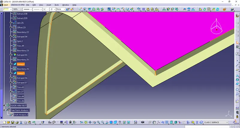
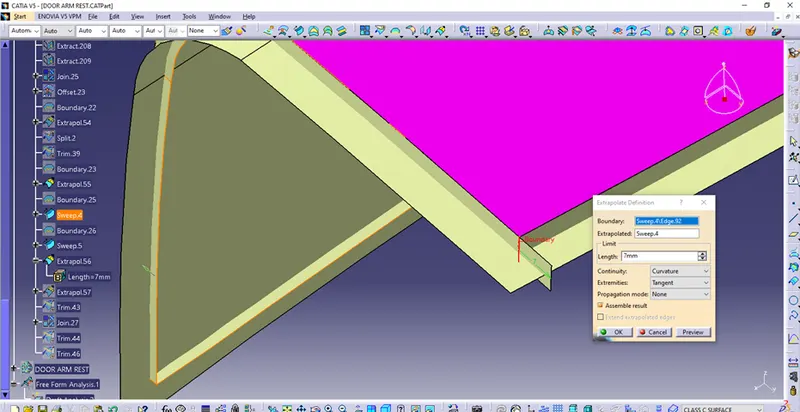
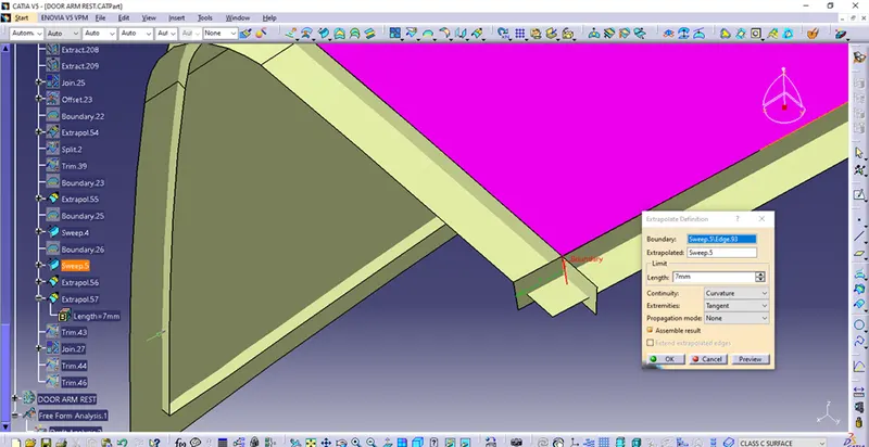
And that trim is a CLASS C SURFACE,that I had needed.
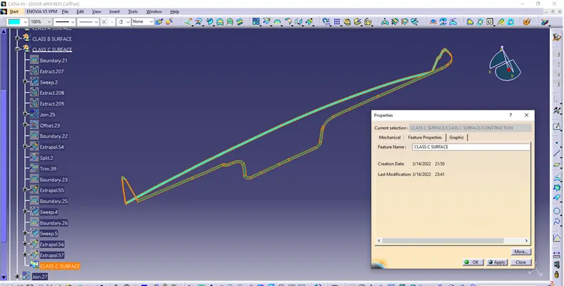
DOOR ARM REST (SURFACE)
Then under construction I have inserted new Geometrical Set called DOOR ARM REST.There I have joined CLASS A SURFACE (I have now renamed the name DOOR ARM REST from INPUT in CLASS A SURFACE as in Geometrical Set to be ready for publication) with a CLASS C SURFACE.
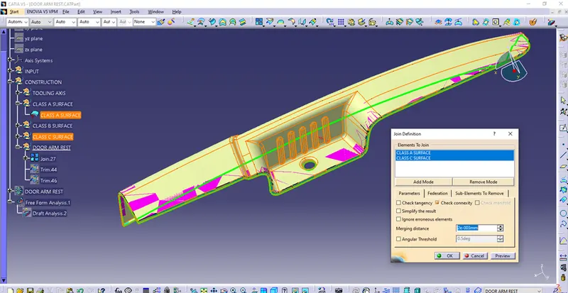
Afterwards I have trimed the last sufaces in following order to get completely closed surfaces that should be able to become Solid Part,that we need for production.
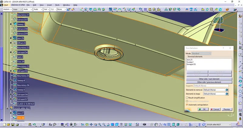
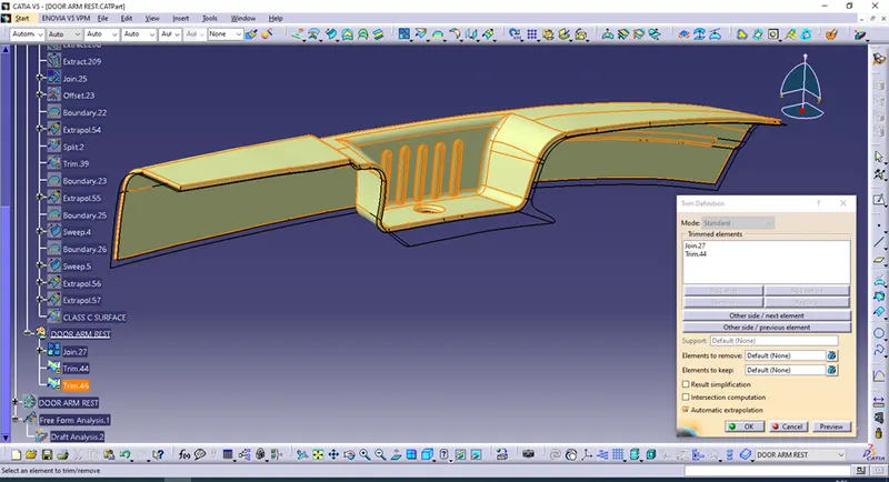
I have renamed final surface as a DOOR ARM REST SURFACE and finaly I can close all surfaces to get a finished Solid Part.
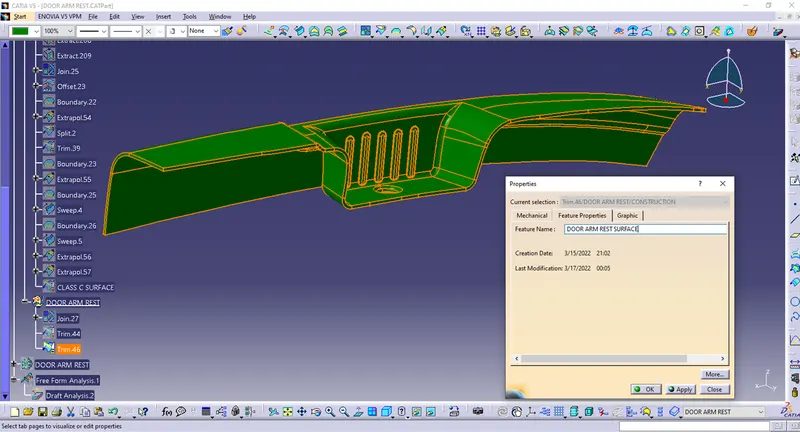
DOOR ARM REST
Now,first I have changed my Workbench from Geometrical Surface Design to Part Design and there I have closed my surfaces as it is shown bellow.
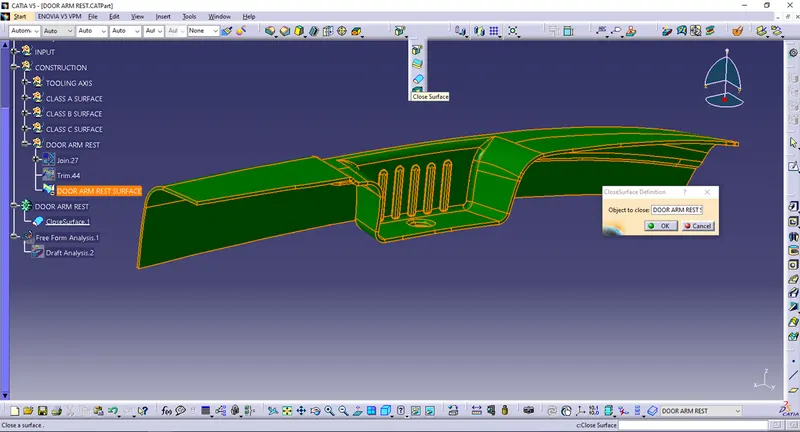
After closing surfaces I have renamed CloseSurface.1 as DOOR ARM REST solid part and changed its graphic properties.
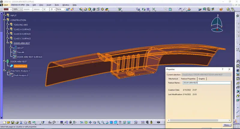
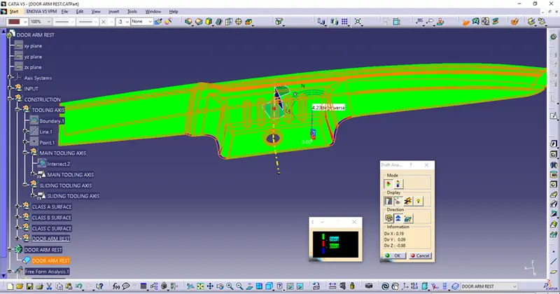
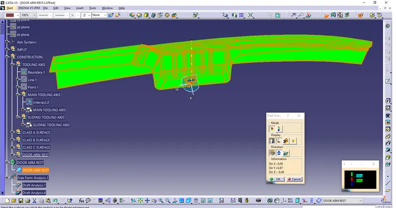
Now I have done final check on solid part with Draft Analysis regarding those two Tooling Axis and get results as it is shown on images bellow.
Obviously,it is clear that,the part with so defined CLASS A SURFACE could be manufactured only with two Tooling Axis and so defined Tooling Axis, as shown on images,could give satisfatory solution to produce Part with minimum 3deg Draft.
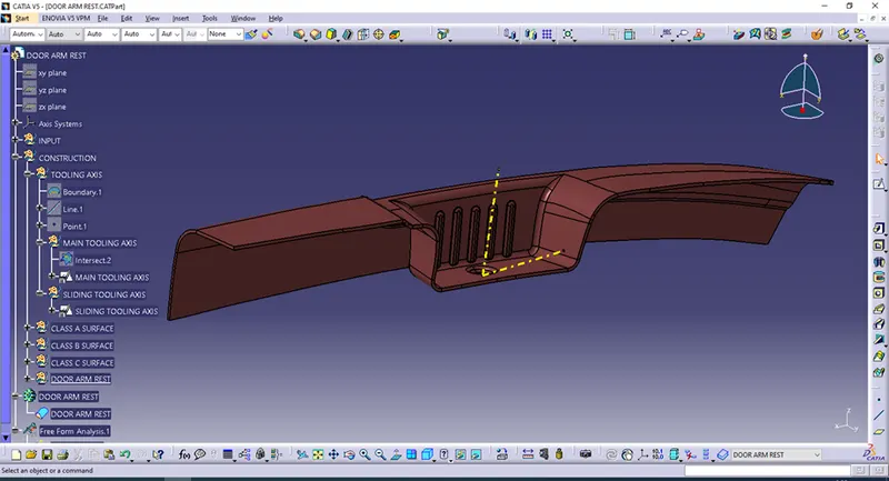
Finaly I have Published all required Features:
MAIN TOOLING AXIS
SLIDING TOOLING AXIS
CLASS A SURFACE
CLASS B SURFACE
CLASS C SURFACE
DOOR ARM REST SURFACE
DOOR ARM REST (Solid Part)
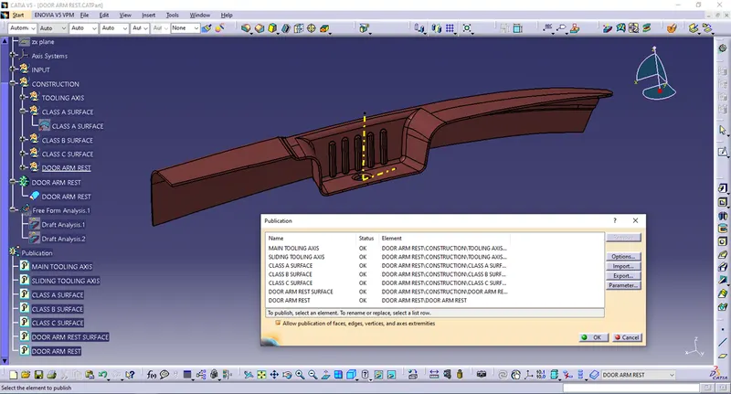
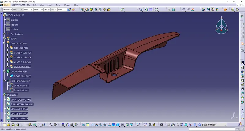
That is all colleagues,Part DOOR ARM REST with Tree Structure is given on image.
The rest of documents - DOOR ARM REST.CATPart and ppt presentation I am sending as attachment.
T H A N K Y O U V E R Y M U C H O N A T T E N T I O N A N D Y O U R T I M E .
Best regards,
Ivan Tole