Week 8 - Challenge 2 - Base Bracket Design
BASE BRACKET
AIM: Create the Base Bracket Plastic component through the given Class-A surface. And perform the Draft analysis on the model.
METHODOLOGY:
Draft Analysis:
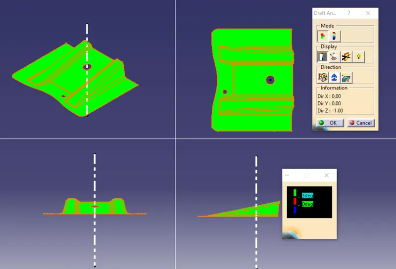
Draft analysis helps to detect if your drafted part is easily removable from the mold (in case of plastic component) or die (in case of sheet
metal). All plastic components will have a minimum draft of 0.5 to 3deg. And for automotive sheet metal parts, the draft will be 7deg or
more. If a mold wall is perpendicular to the part ejection, there is ample friction or interference between the mold and the part which will
not allow one to release from the other. This is why design engineers give a minimum draft to the part. In CATIA V5 the feature draft aralysis
dialog box looks like this:
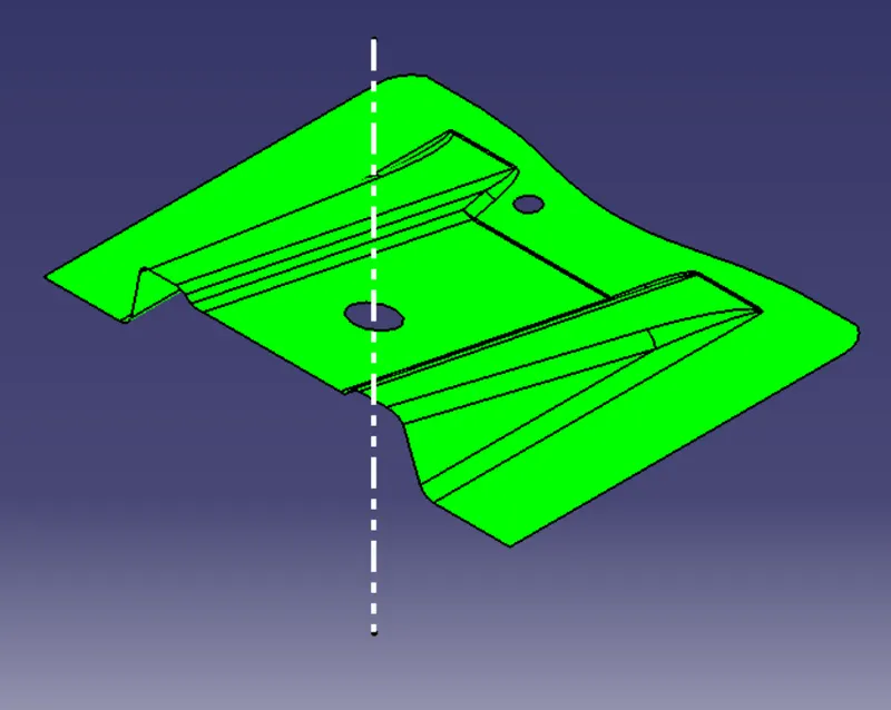
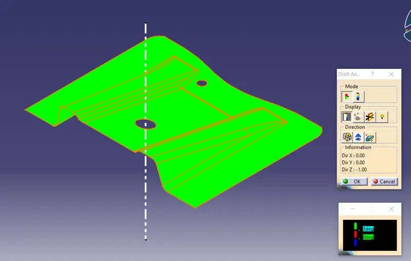
Tooling axis;
The tooling axis is defined as the direction in which the mould opens or core and cavity opens and closes. The selection of the correct
tooling axis is important to ensure the component is taken out perfectly and also the cost of the component should be less. I will start by
inserting a geometrical set and naming it as a tooling axis. For creating the tooling axis I will analyze the model and first create the dummy
tooling axis. So on analyzing the model I found out that the z-axis will be perfect for creating the tooling axis. Because along the Z direction,
only the whole component is visible.
First, I will create a point on the bigger hole and from that point, I will create one line along z-direction that will be my dummy tooling axis.
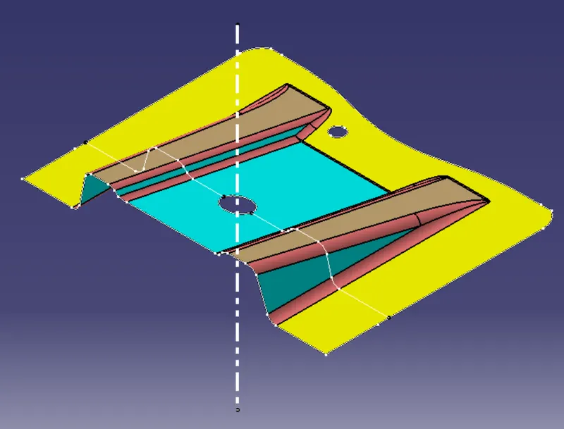
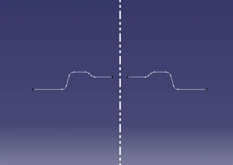
Then form the bisecting lines to confim ejection process should be made without any problem.
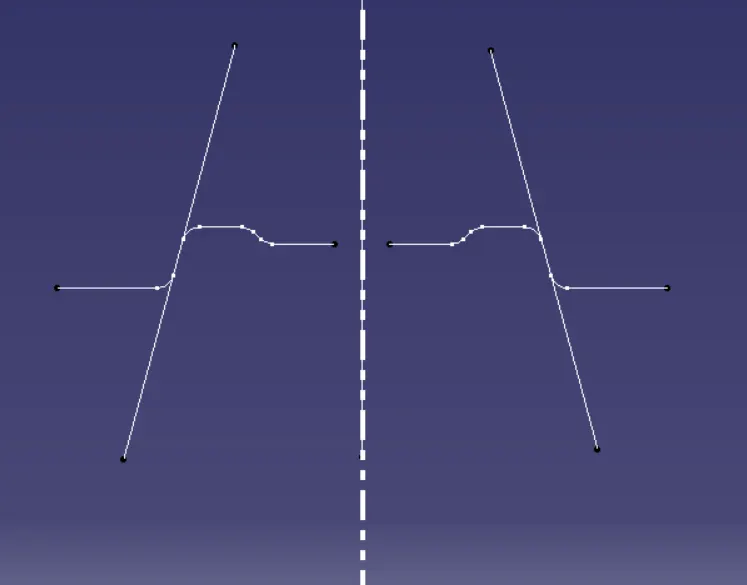
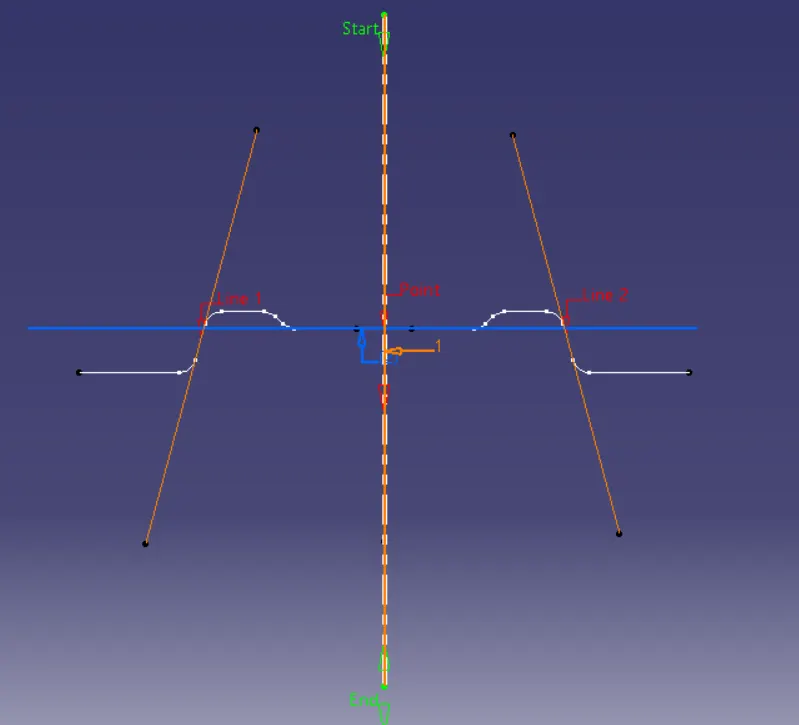
CLASS- B surface;
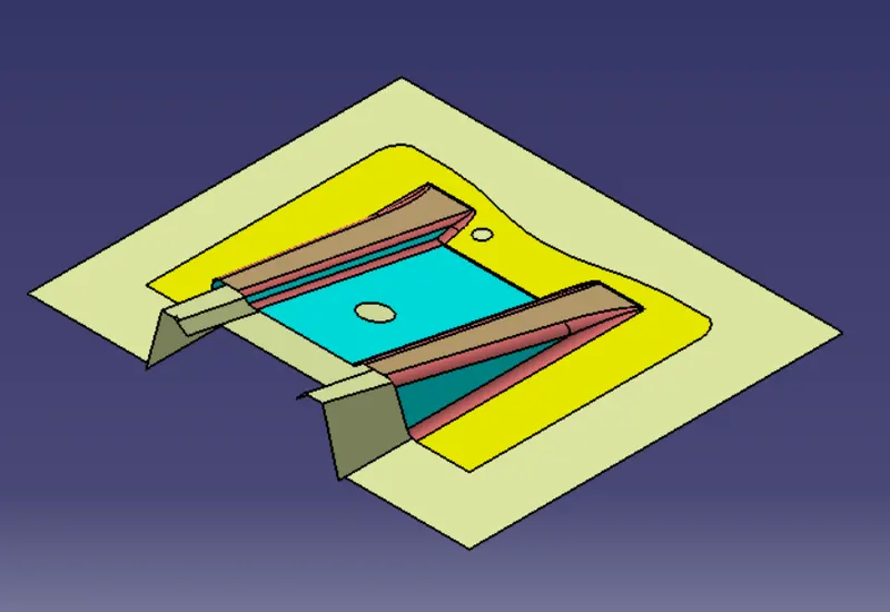
CLASS- B surface is created by extracting each wall and un-trimming and extrapolating the walls to obtain the shape by trimming the excess
surfaces and offsetting it to a certain distance based on the thickness of the model. The offset surface will be the B-surface.
CLASS- Csurface:
The surface created using sweep command by sweeping the boundaries of A-surface along the tooling axis to connect from A to B-surface
is known as C-surface.
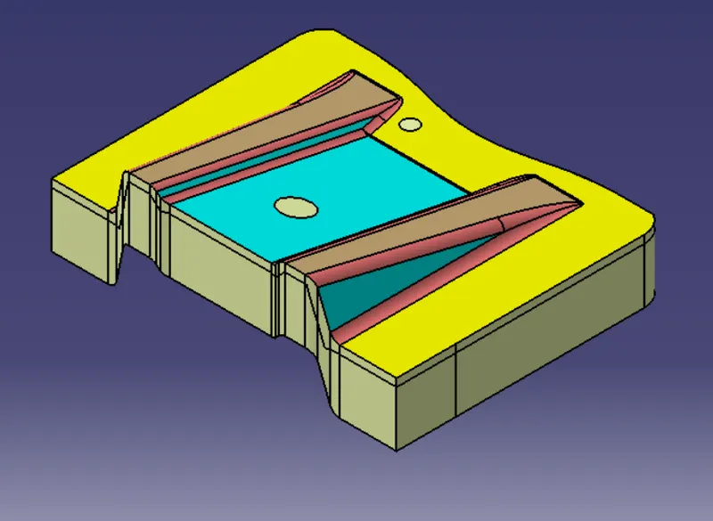
TRIM CLASS A AND CLASS B TO FORM CLASS C SURFACE
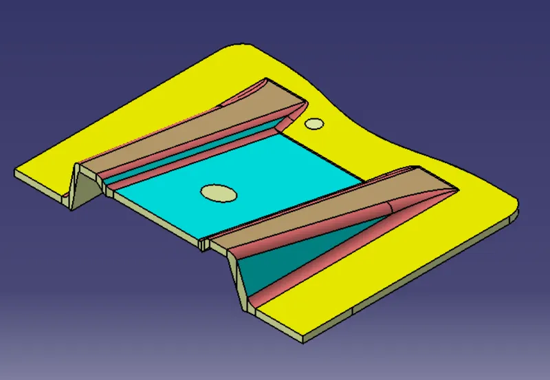
HOLES OPERATION TO E PERFOMED
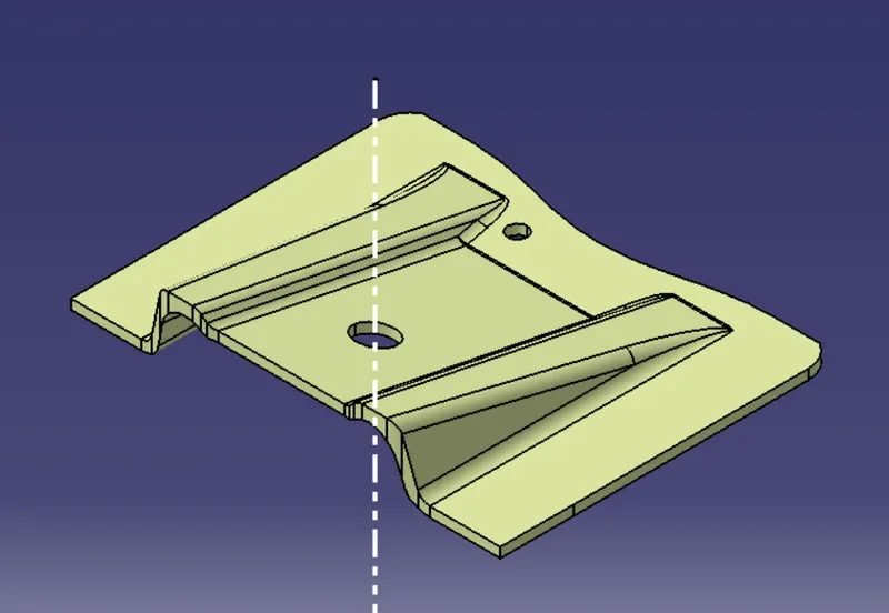
CONVERT TO PART FEATURE TO MAKE A CLOSED SURFACE
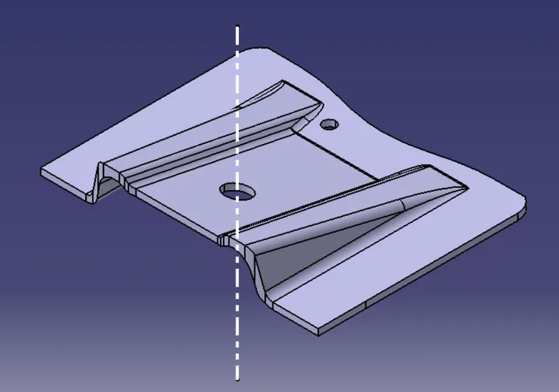
draft angle in various orientations
SURFACE MODEL VARIOUS ORIENTTATIONS
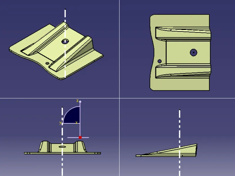
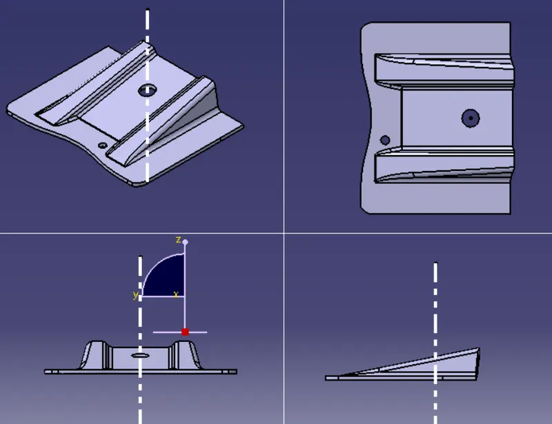
SOLIDMODEL VARIOUS ORIENTATIONS
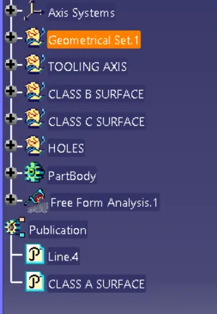
TREE STRUCTURE