Week 8 - Challenge 2 - Base Bracket Design
Base Bracket Design
The objective of this project is to Create the Base Bracket Plastic component through the given Class-A surface.Along with the Tooling axis and the Draft analysis on the component.
INTRODUCTION
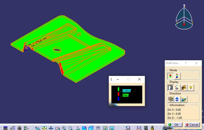
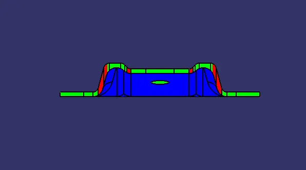
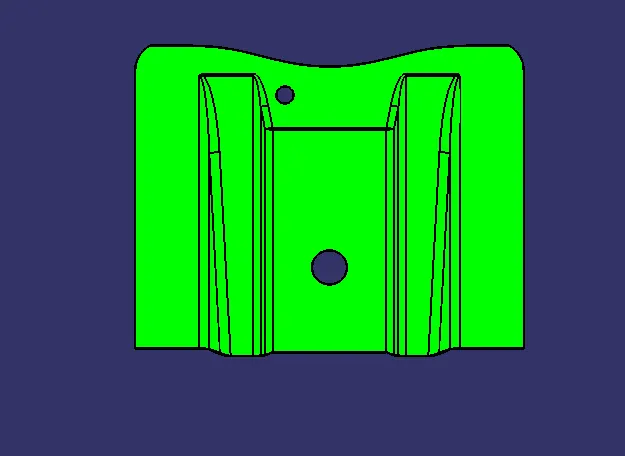
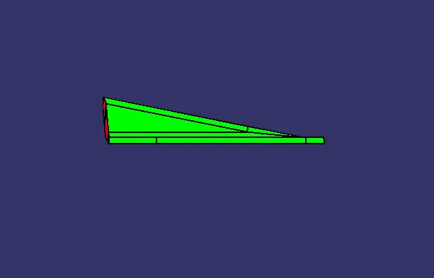
The Draft Analysis command enables you to detect if the part you drafted will be easily removed. This type of analysis is performed based on colour ranges identifying zones on the analyzed element where the deviation from the draft direction at any point, corresponds to specified values.
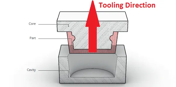
Tooling direction is the main consideration for plastic part and mould parts because it defines the movement of the mould part and the possibility of the plastic part coming out from the mould part (Core and Cavity).
TOOLING DIRECTION
The Tooling Direction is basically the direction that the mold pulls apart. The mold is built in two separate pieces, basically. You have a Cavity side and you have the Core side. The Core pulls apart from the Cavity and that's the Dyeline or the Tooling Direction.
PROCEDURE FOR CREATING TOOLING AXIS
Firstly import the given class A surface to the catia.
- Check For any defects in the surface such as boundries and estimate the possible tooling direction
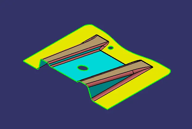
Create an intersection curve between Class A and Y-axis
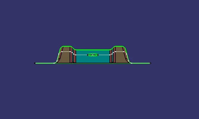
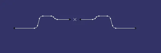
Select the area where the draft is required and create a bisecting line between those two lines
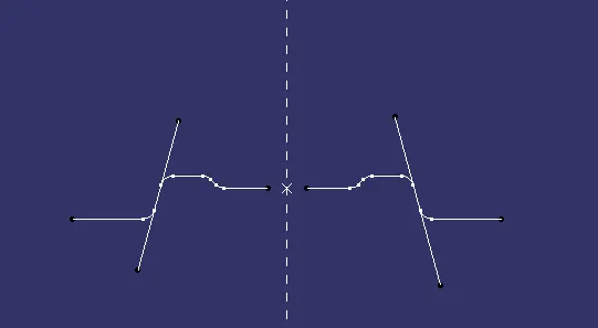
The resulting Bisecting line will be the Tooling axis
Draft Analysis
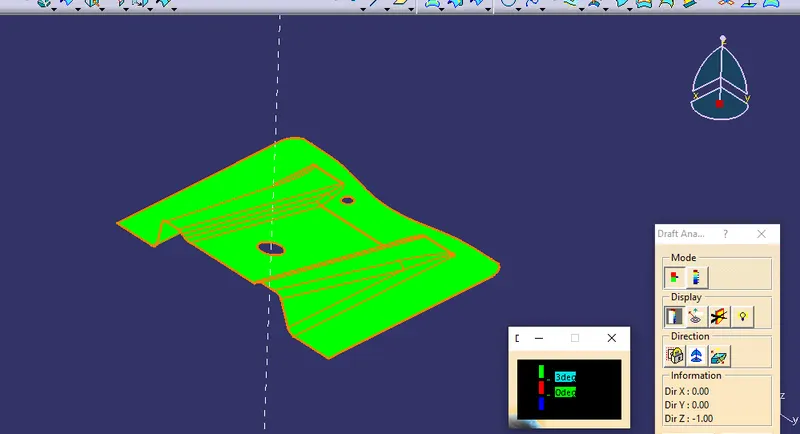
Using the feature draft analysis, perform draft analysis on the surface considering the tooling axis
3 degrees draft is optimum for the plastic moulding component
CREATING B-SURFACE
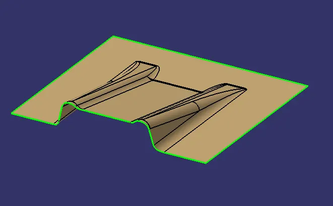
To create the B surface offset the parts of class A surface without fillets
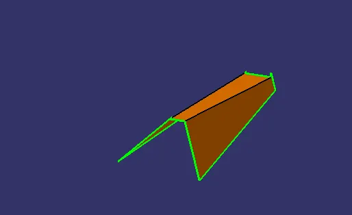
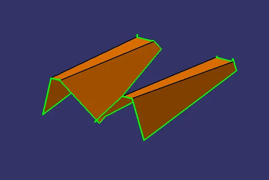
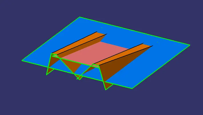
After offseting the parts of the class A trim them all to create B surface
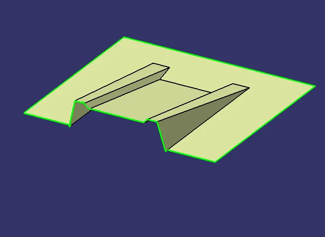
Finally add the fillets to complete the B surface
CREATING C SURFACE
To create C surface Use sweep of 3deg w.r.t tooling axis From the boundry of the class A surface
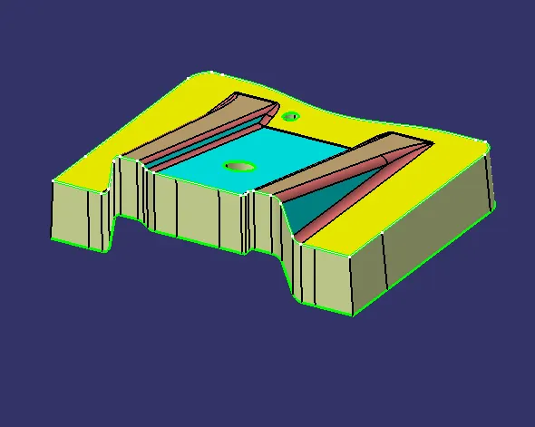
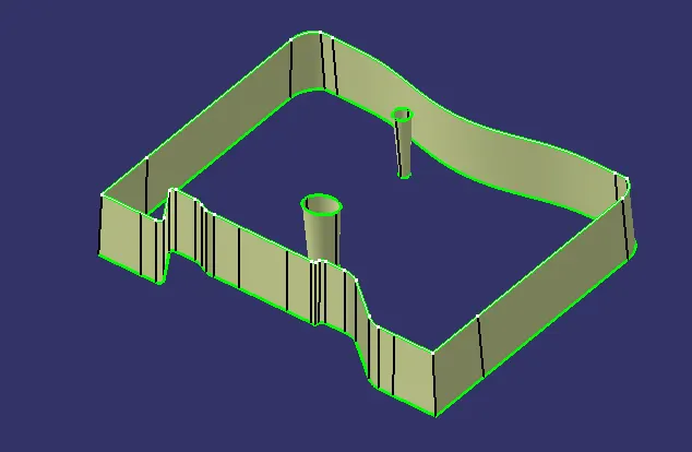
Finally Trim the A,B,C surfaces to create final surface component
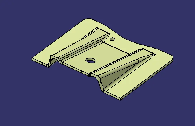
Use the option close surface to create a part body from the surface component
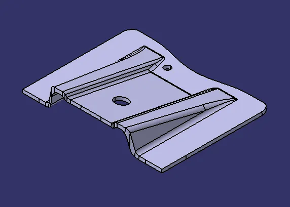
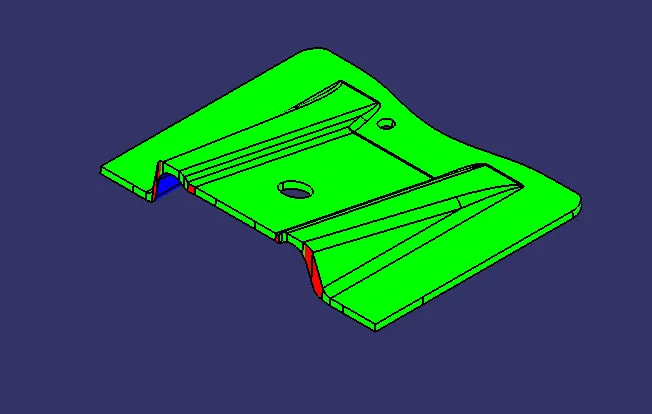
Perform Draft analysis on the final component
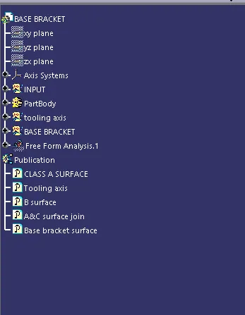
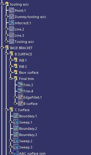
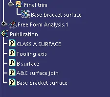
Tree Structure for the Geometrical Sets