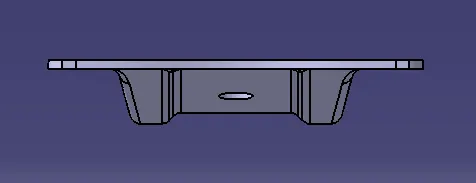
Week 8 - Challenge 2 - Base Bracket Design
AIM:
Create the Base Bracket Plastic component through the given Class-A surface and perform the Draft analysis on the model.
OBJECTIVE:
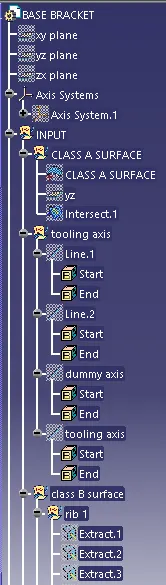
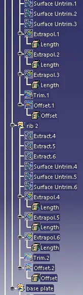
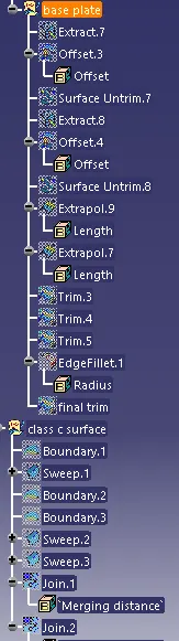
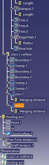
- Ensure Proper Tree Structure.
- Geometrical sets should have a proper name based on the sketches present inside of it.
- All the sketches should be created under the Geometrical set.
- Use the Close Surface feature to make a solid body from the surface.
- Use the publication option and publish the below
- Tooling Axis
- Class A, B, and C surface
- A detailed report should be done explaining the draft analysis and the tooling axis creation.
- An explanation should be given on the way of creating the tooling axis particularly the Bisecting method.
PROCEDURE:
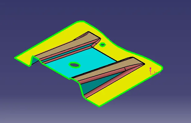
Step-1: Connectivity check
- First we have to verify the part design using join surface option by simply selecting the class A surface .
- Another method is create a boundary layer of surface and disassemble it from the boundary layer from the surface.
Step-2: Create tooling axis (Bisecting method)
- Create a reference point by selecting the center circle of surface.
- Then create the axis for the surface to easily define the tooling axis.
- simply select the point and xyz plane.
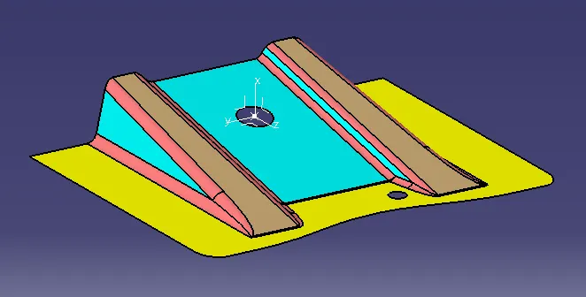
- To get a dummy tooling axis in x direction.
- Use the intersection command, to get a wire diagram of surface in x direction.
- select the intersection command, select first element is plane of dummy axis say zx plane, select second element as class A surface, click ok.
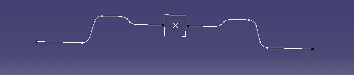
- The draft angle of x direction is created to get the tooling axis of x-direction.
- Select the line command, select the perpendicular line's points and drag for desired distance. and same on other side too.
- Then use bisect line command to create a bisecting line between the draft angles..
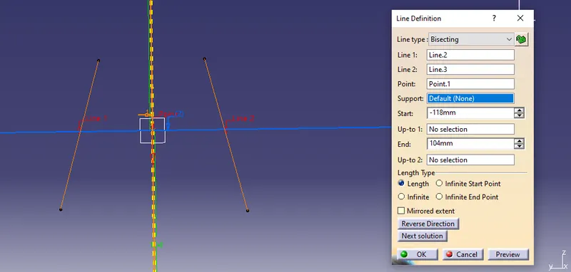
- We will get the tooling axis in x-direction and also define its line color and thickness
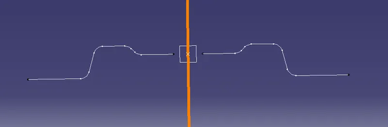
- After the dummy axis definition, select the tooling axis of x to bisect using line command.
- The tooling axis for draft analysis is formed.
- Use publication command to publish the class A surface and tooling axis.
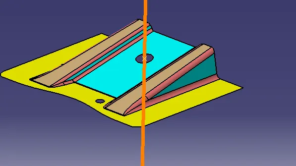
Step-3: Perform draft analysis
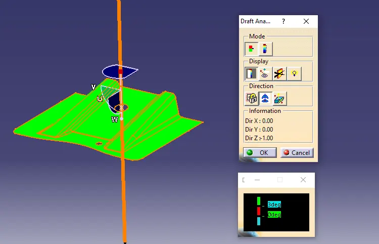
- Select the draft analysis command, ensure the material feature is used.
- Use quick analysis mode, display color scale option.
- Click on compass command on direction, drag and drop it in tooling axis.
- The draft should show green surface which is feasible draft angle.
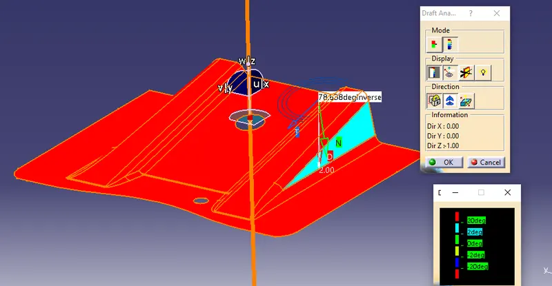
- If red is shown not feassible draft angle and for blue negative draft angle.
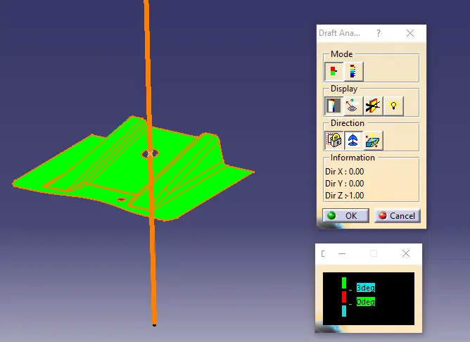
- Use analyses under running point, to ensure same angle on symmetrical direction.
- Below is fully analyze mode to get the varied angle in class A surface.
Step-4: Create class B surface
- First extract the side draft surfaces from the class A surface.
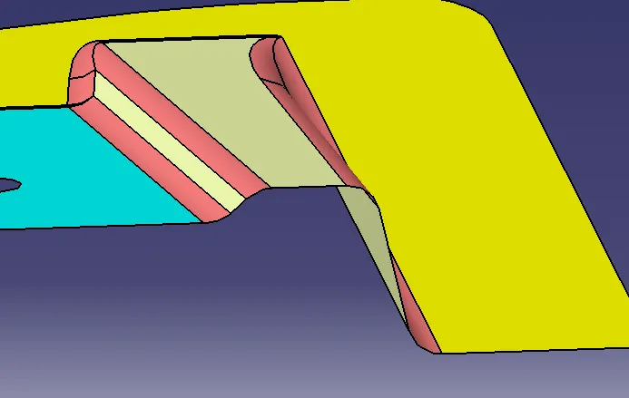
- Then untrim the surface to extend the edges.
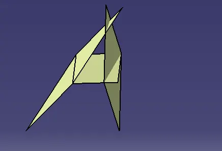
- Explorate the surfaces for 10mm length with boundary to be specified.
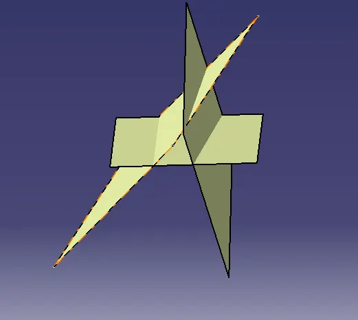
- Trim the excess edges by selecting the surfaces and other side option to switch the parts to be trim.
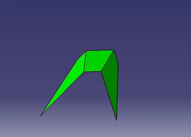
- Then offset the trimmed surafce from 2.5mm.
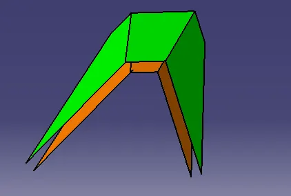
- Follow the same process for other side too.
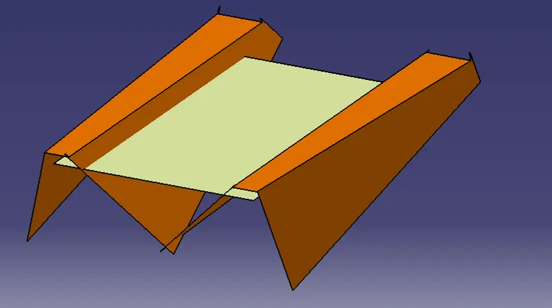
Step-5: Create class C surface
- Do same procedure to creaate the class c surface from the top and bottom of the class A surface.
- And trim the side and top surfaces together.
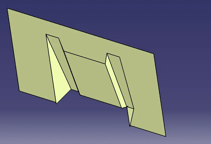
- And apply the fillet option as 3+2.5 mm for all inner edges.
Step-6: Join the surfaces together
- First creaet a boundary of class C surface to from a guide curve.
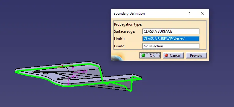
- Then click the sweep option to select profile type line, draft doirection, guide curve as boundary layer and draft direction as tooling axis.
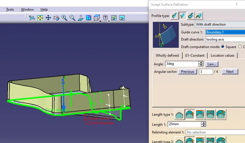
- Follow the same procedure to attain the top layer and 2 holes.
- Then join the side sweep and top sweep togther and 2 holes as well.
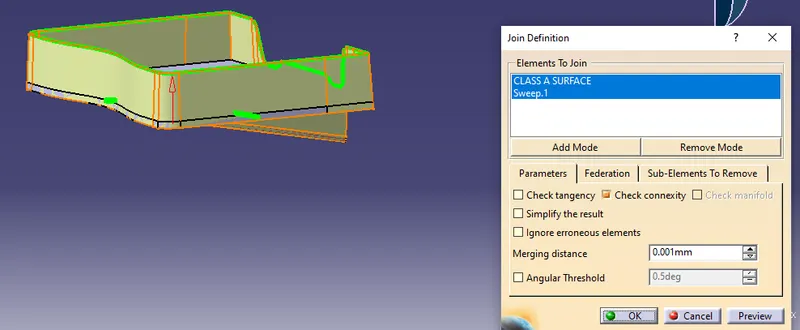
- Finally trim the joined surfaces and class C surface to get the final result.
RESULT:
- Tree structure
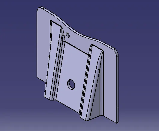
- Isometric View
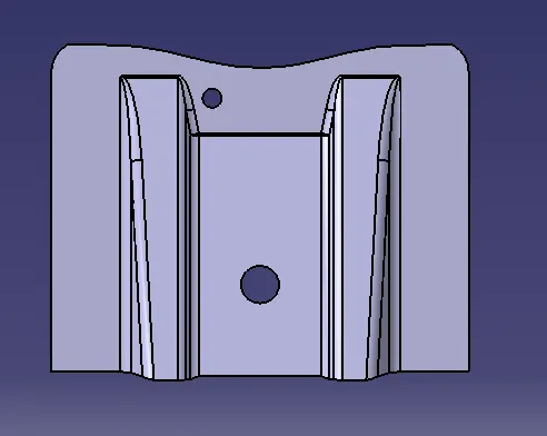
- Front View
- Side View
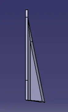
- Top View