Week 8 - Challenge 2 - Base Bracket Design
Objective:-Create the Base Bracket Plastic component through the given Class-A surface. To begin with, the tooling axis for the given Class-A Surface should be created meeting the requirements of the draft angle and at the end perform the Draft analysis on the model.
Detailed Report:-
1. Checking the continuity of the given class A surface.
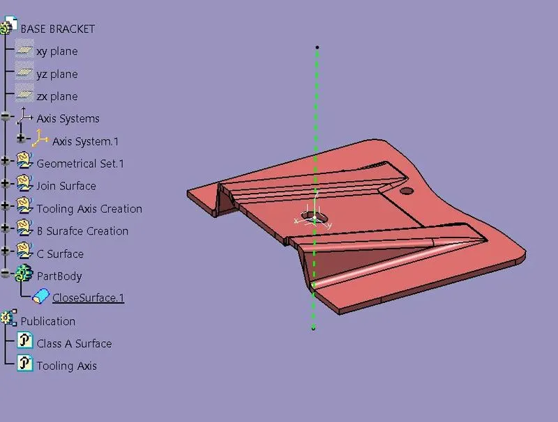
First we open the given igs file which is seperate surface. now join this suface through join command which is available is GSD workbench of CATIA.
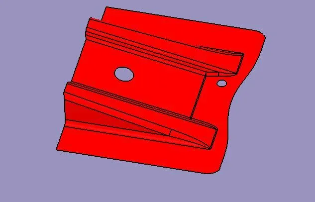
This image shows the given input surface of the model.
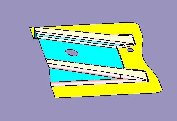
When we going to joining this face this error at the red boundary which means this surface is not good.
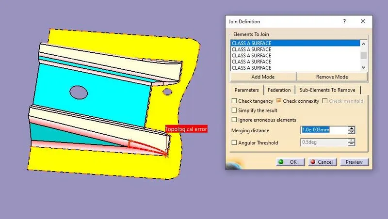
after little bit modification of error surface we can join all the surface and obtain Complete model of A class Surface.
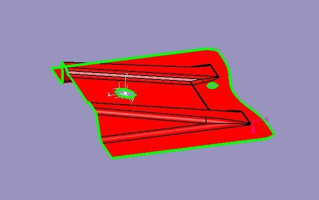
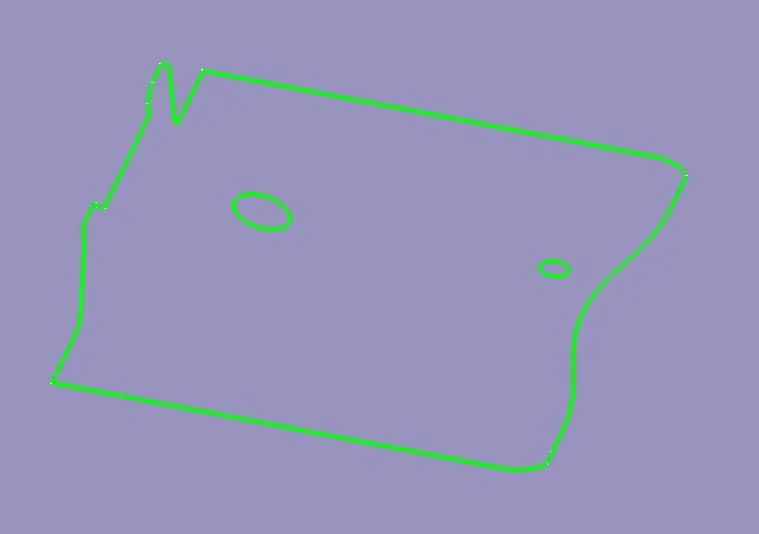
After joining the surface we check the continuity of the given given class A surface through boundary cmnd . The green line in the given below image shows the boundary of the given class A surface. If green line show in the between of the surface means surface is not joint at that place.
This is the continuous boundary of the class A surface and two hole boundary of the base bracket which may provive for the fixing purpose.
2. Creating Reference point, reference axis & Dummy tooling axis.
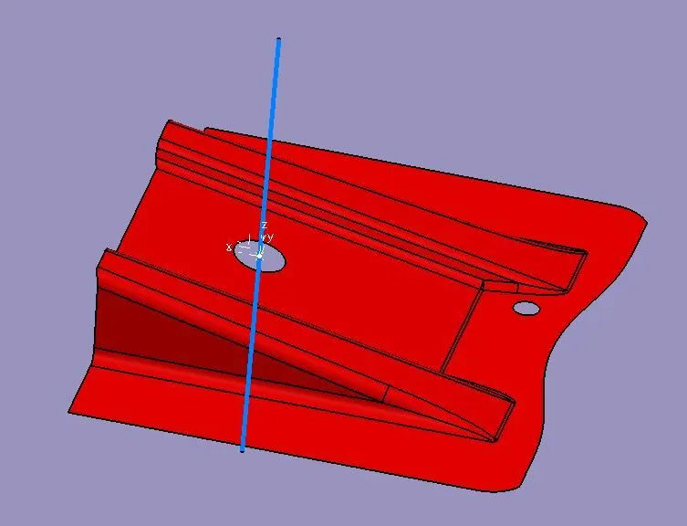
The point show at the centre of the hole is the reference point at that place we create a axis system through axis command.
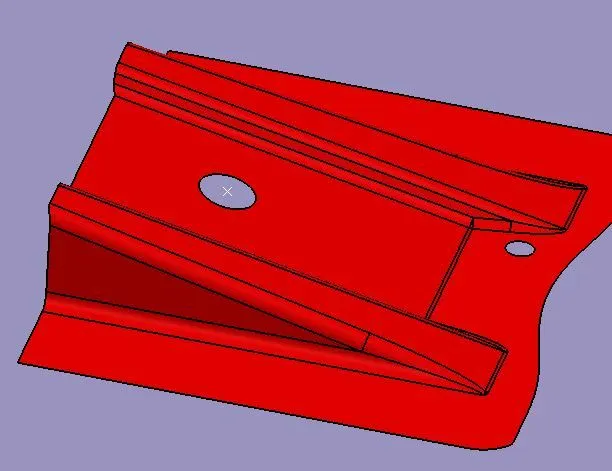
Below there is is axis system which is created by axis system command.
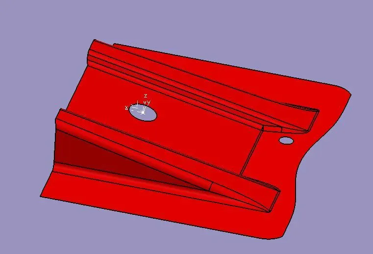
Blue line show the dummy tooling axis which is created by line cmnd (Point & direction)
3. Creating tooling axis.
Tooling axis is that axis where core and cavity open and closed. Every mold have one main tooling axis on that all mould open and closed.
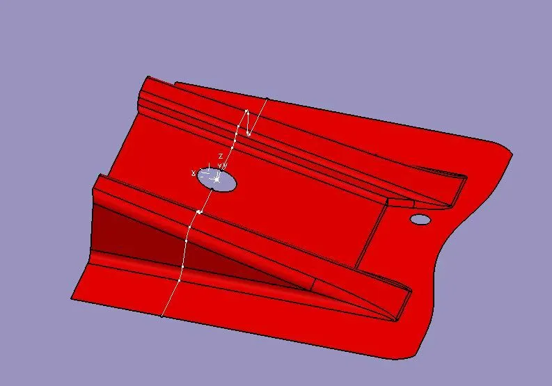
Use intersection command intersect the Class A surface and Y-Z plane for that a intersection line created which show below in white colour.
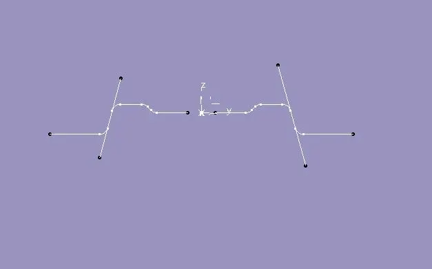
Using Line cmnd (Using point to point) we create the line which below on the image.
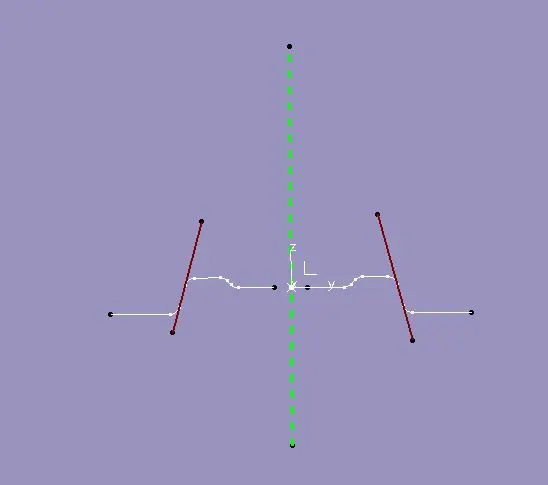
Using bisecting cmnd under line comaand we create a line which show brown clour in the below image.
In this Given model there is no need to check the other direction of intersection. So finally this Brown colour dotted line is the main tooling axis of this component.
4. Creating B- surface
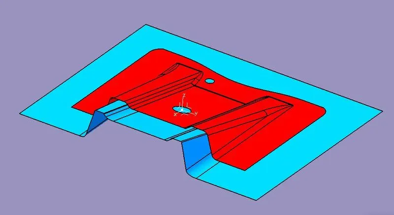
B- surface is that surface which create from the class A surface. B surface provide the thickness of the part. in the below image this is creation of B-surface using varion command like extract,untrim, offset, extrapolate.
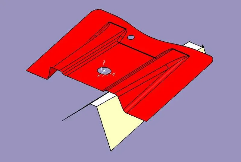
The below image show the B surafce which is Sky blue in colour.
5. C class surface creation
C class surface is that surface which is join the class A & b surface along the tooling direction.
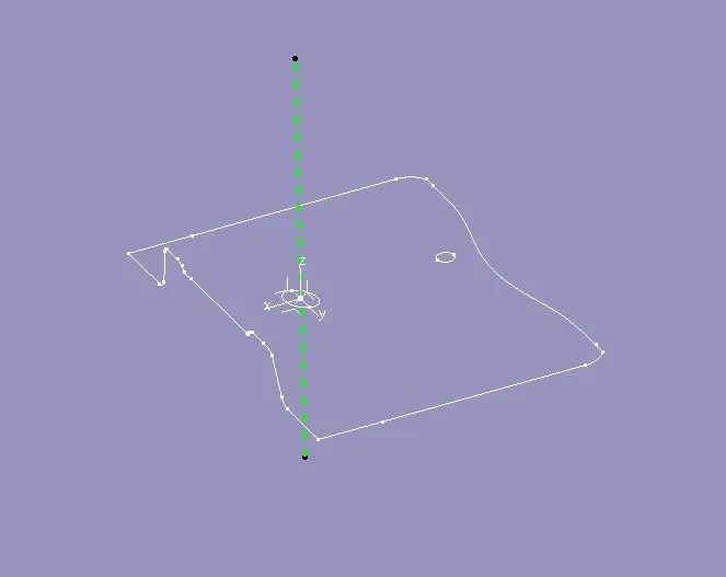
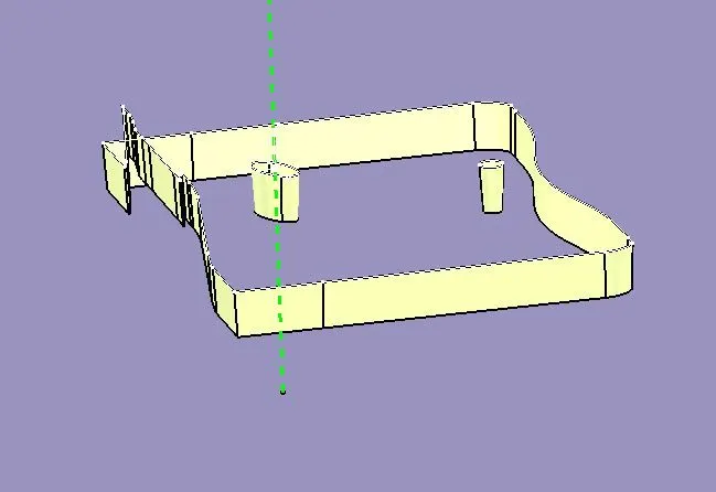
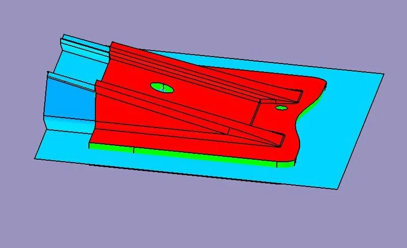
C class surface created using sweep command for which we use the boundary of class A surface. the cyon color shows the C surface on which we provide 3 degree draft along the main tooling axis. this is negative draft according the seeing the component parting line.
In the below image
| A class Surface | Red colour |
| B Surface | Sky blue colour |
| C Surface | Green Colour |
6. Joining the A,B & C surfaces.
Using join command first we join the class A surface to C surface.
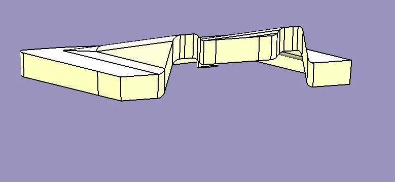
After that using trim command we join the above joining surface to b surface.
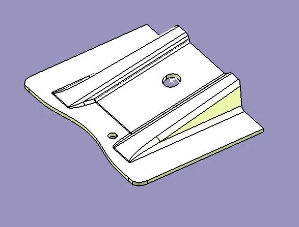
after that we checking the joining condition of all these three surfaces thorugh boundary command if it shows error which means all surface closed properly.
now going to part work bench and apply closed surface command to make solid the above closed surface & finally we get solid model. White color shows the solid model.
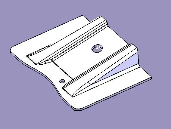
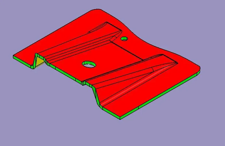
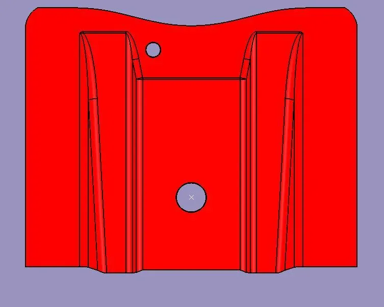
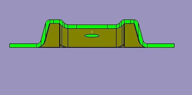
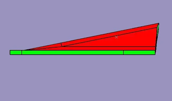
7. Different view of the base bracket model
| Red Colour | A class Surface |
| Green Colour | C Class Surface |
| Yellow Colour | B class Surface |
Isometric View
Top view
Front view
Side View
9. Draft Analysis
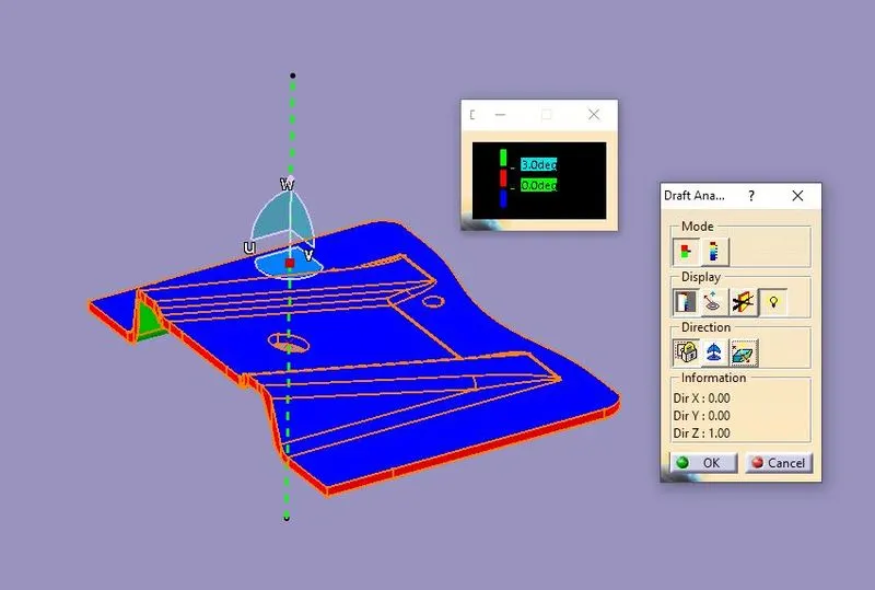
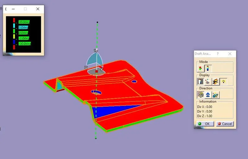
Using feature draft analysis command, first move the compass along the direction of tooling and there after lock the compass tool then click on the model.
The below image show the first colour output on the model in which green colour show the cavity side of the model and blue colour shows the core side of the model.
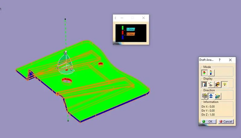
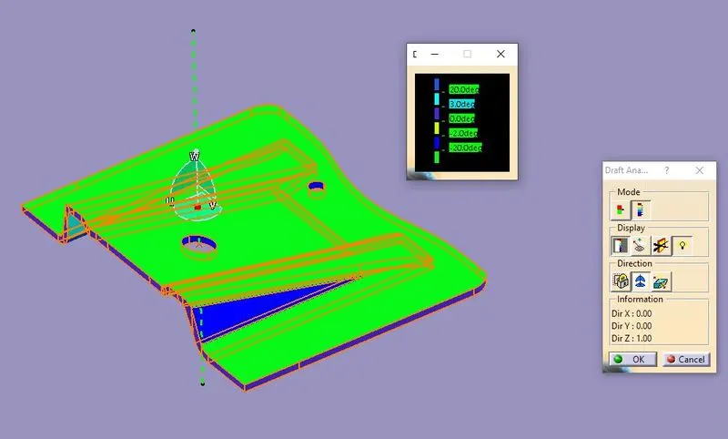
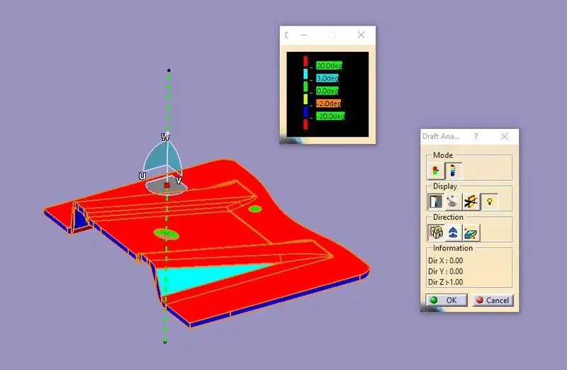
The different colour varient shows the diffrent draft angle pn the model.
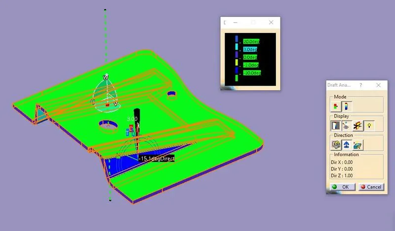
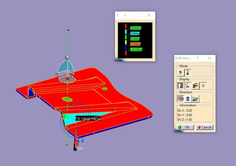
Tracer shows the angle on the particular face.
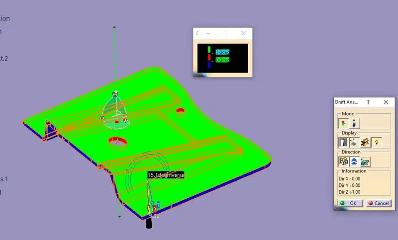
If we change the direction of draft its showing like below given image.
Finally, Tree structure on the below image.