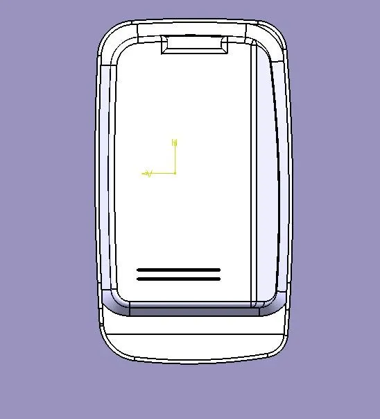
Week 9 - Attachment Feature Creation - Challenge 1
Objectve:- Create the rib for the Centre console coin holder considering the design rules mentioned in the video.
1. Input surface:- Open the igs file in catia workbench. This surface is seperate each others.
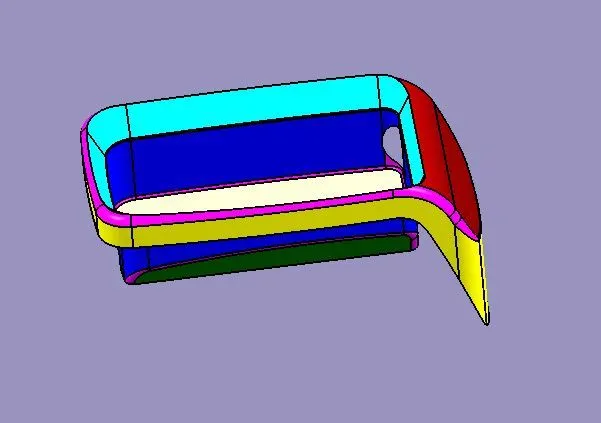
2. Joining Surface:- Using join cmnd we join all surface together and obtain complete A class surface. the tolerance between class A surace is 0.003 mm which is easily maintain in this model and no surface defect found in this model.
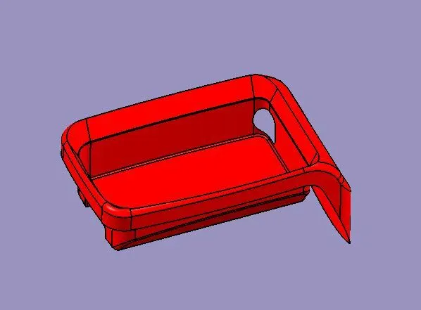
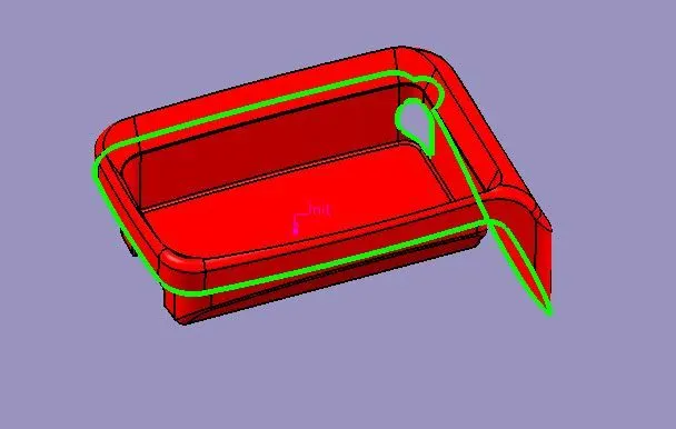
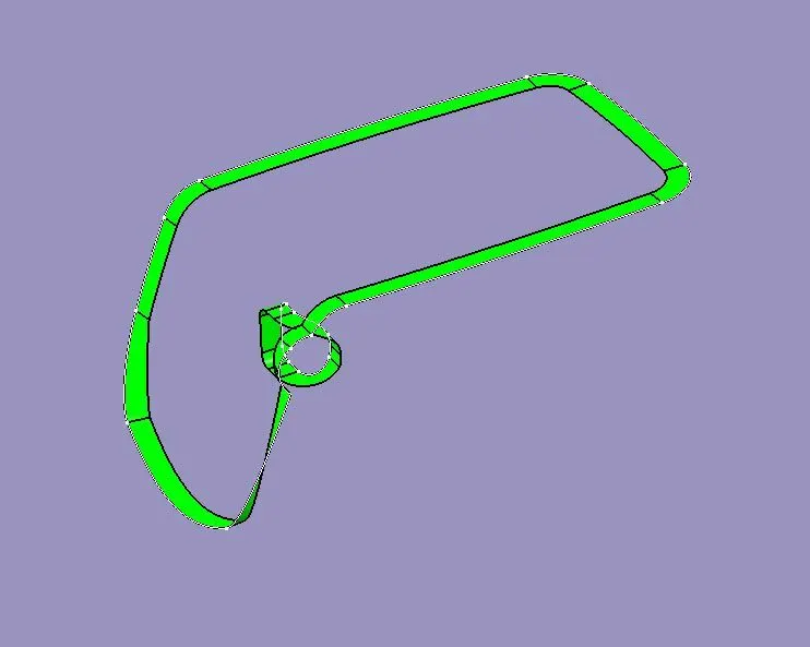
Checking the boundary condition of the given class A surface here shown green line which the boundary of the given class A surface.
3. Creating Tooling Axis:- first we create the reference point on the bottom surface of the given class A surface which show the yellow in colour on the below image.
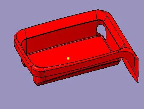
Creating axis system on the reference point.
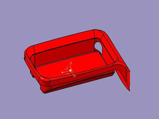
Creating dummy tooling axis which show in white colour in thew below image.
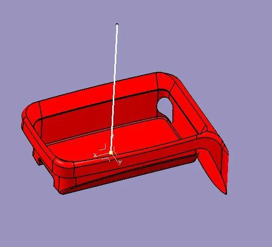
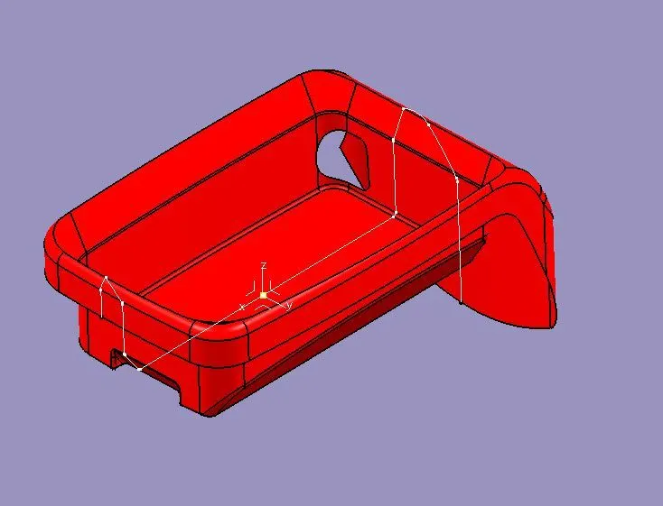
Creating Intersecton curve from class A surface to y-z plane, below white colour line shows the intersection curve of the A surface.
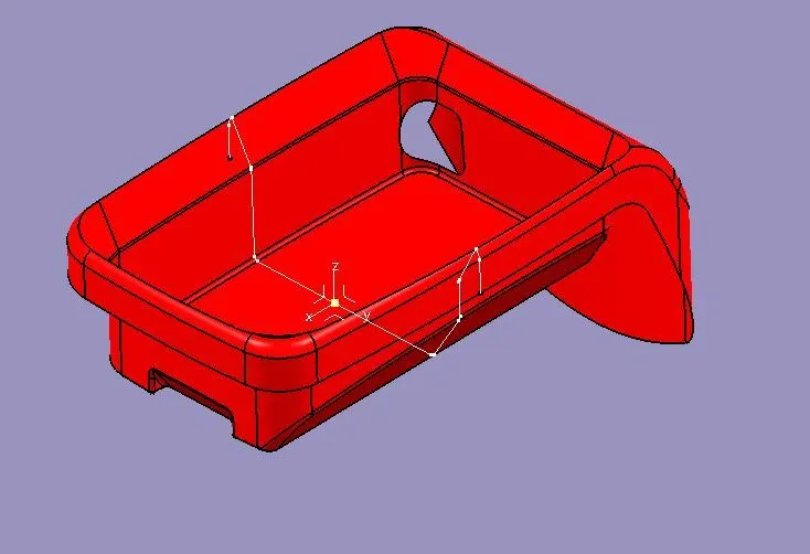
Creating line from point to point which show in yellow colour on the other hand we create bisecting line with the help of using these two yellow colour line. bisecting line shows in green colour line.
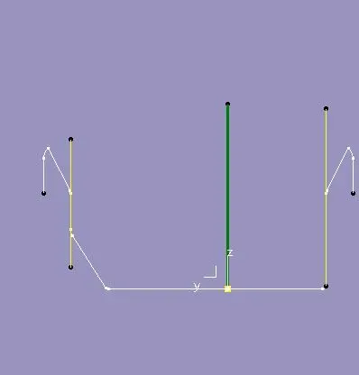
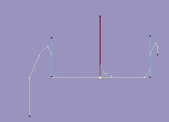
Again using intersection cmnd intersect the class A surface to x-z plane, White colour curve show the intersection curve.
Again creatin gthe line and bisector line as we above use. Brown colour shows the bisecting line. After observing of green colour line and brown colour line they are aling that means we choose a tooling axis any one of them.
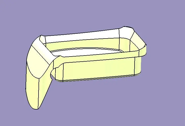
4. Creating B surafce:- first we extract the A surface and using various cmnd like extract,offset, untrim,split,extrpolate etc we create a B class Surface which is orffset 2.5 mm form A clas surface.
5. C-surface Creation:- Extracting the boundary of the class a surafce we get a white colour curve. afterthat we use sweep cmnd to sweep cmnd a surface which is show in the below image. This surface is the C class surface.
Joing All three A,B & C surface using join and trim comnd.
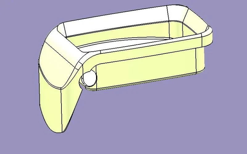
6. Closed surface:- In part workbench using close surface cmnd we close the all surafce and get the solid model. the model show below is solid model.
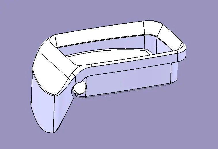
Isometric view
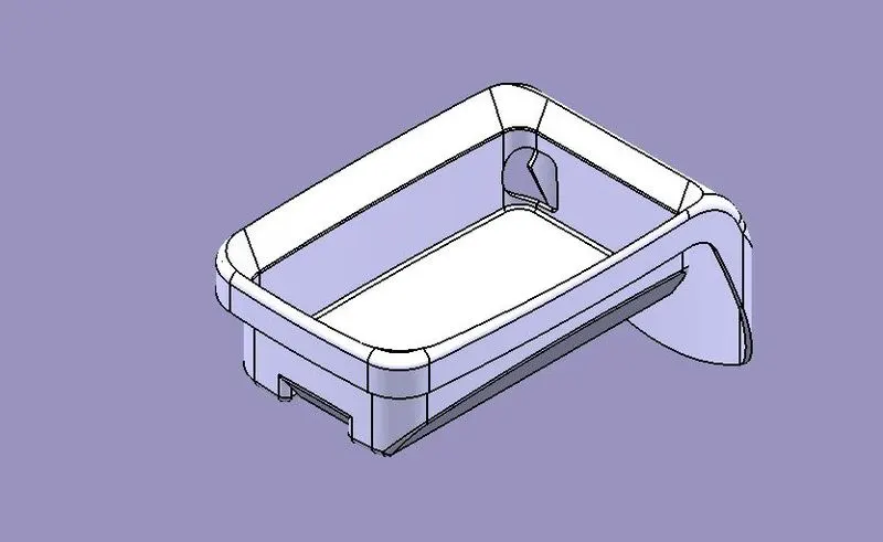
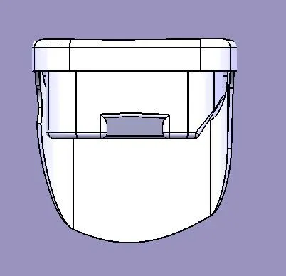
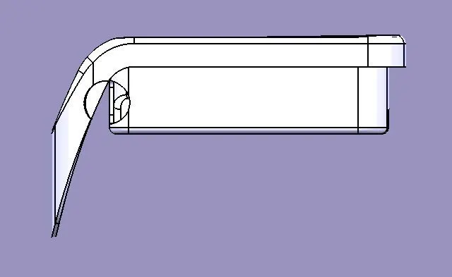
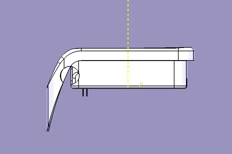
Front & side view
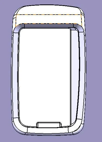
Top view
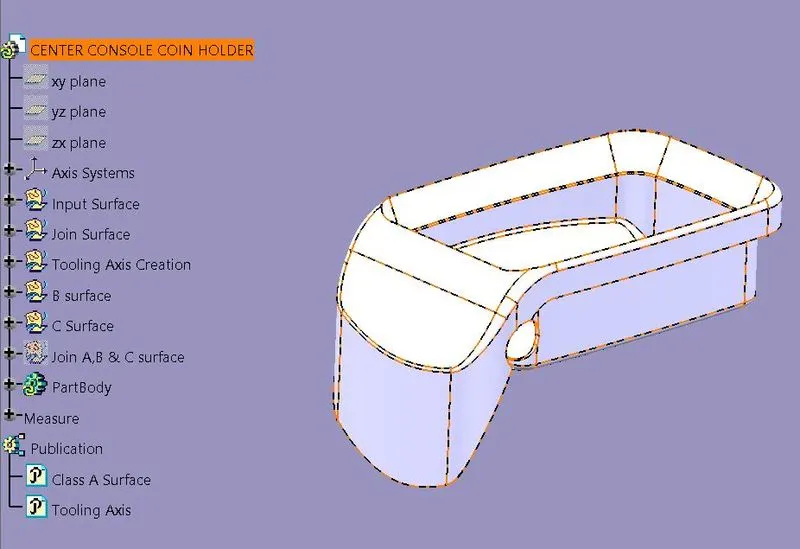
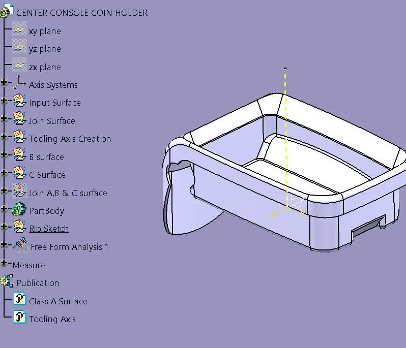
Tree structure of the center coin holder of the model.
 \
\
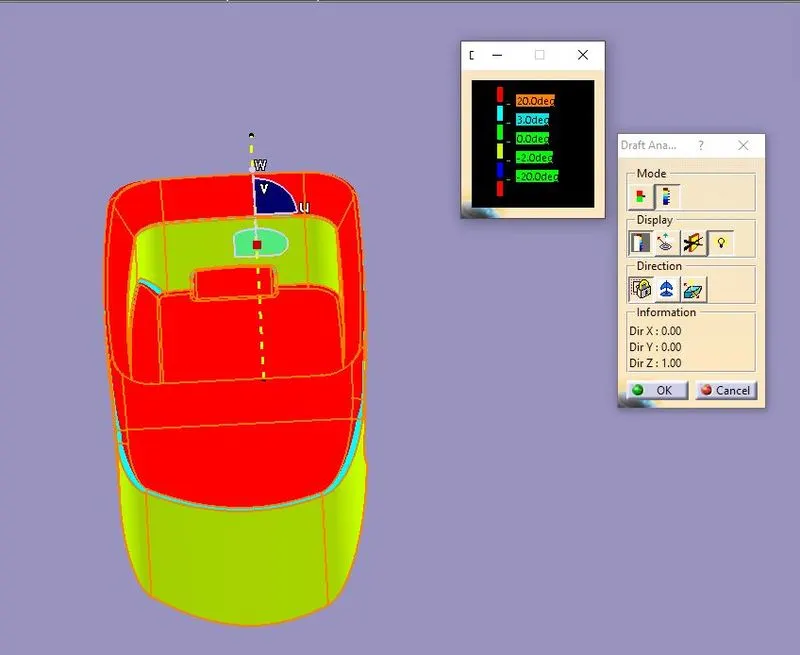
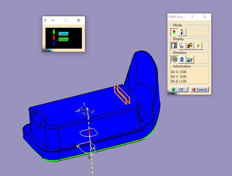
7. Draft analysis:- Using feature draft analysis command we analysis the draft of the model. First we aling the compass to the tooling axis direction afterthat lock the compass and click on the model we get the color varient of the draft angle under the material mode view.
Here we clearly see the side wall is blue colour which means there is no draft on the surface which means this part not feasible for tooling purpose (Injection mold die) so we concern the Class A designer that please prove some draft on the side wall surface for which this part feasible for tooling purpose.
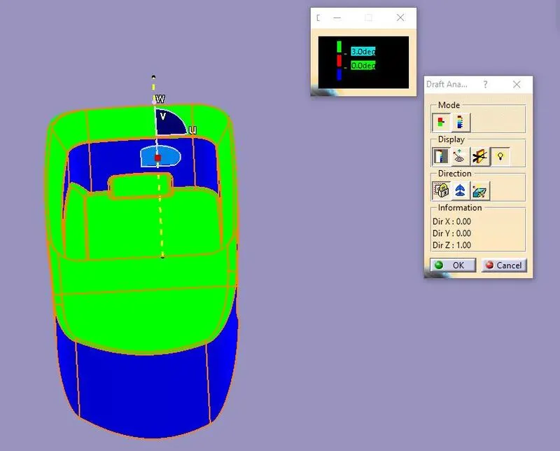
Multiple color varient mode draft analysis on the below image.
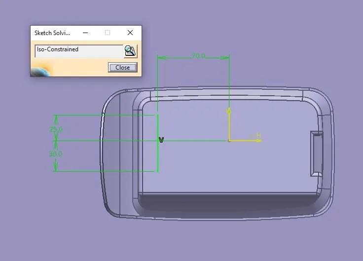
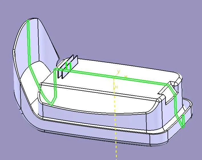
8. Rib Design :- First we create the iso-constrained sketch where we have to required draft. below image show the sketch image.
Now we have create two rid according to design standard which is follow in every oem.
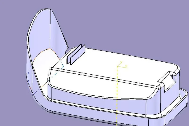
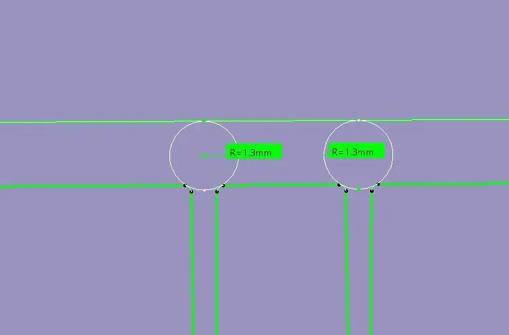
Creating section curve to analysis of the rib thickness which is under design parameter. we create tanget circle to check the thickess at the root area of the rib which is 30% of the nominal wall thickness of the part
9. Checking draft analysis of the design rib.
We pad the sketch of the rib along the tooling direction and provide draft 0.5 deg which is the min draft of the rib and provide root radius which is optional (0.25 mm). this radius will provide the more strength to the rib.
Below image is the colour mode varient to see the draft analysis.
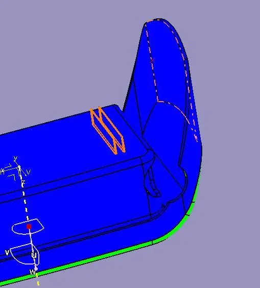
This is the multicolour varient mode to checking the draft analysis.
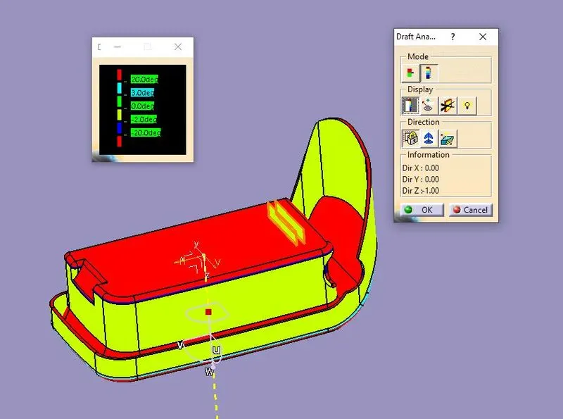
10. Tree structure of the rib design
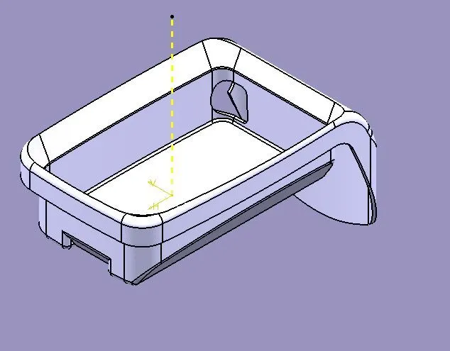
11. Different types of view of the model
Isometric view
front View
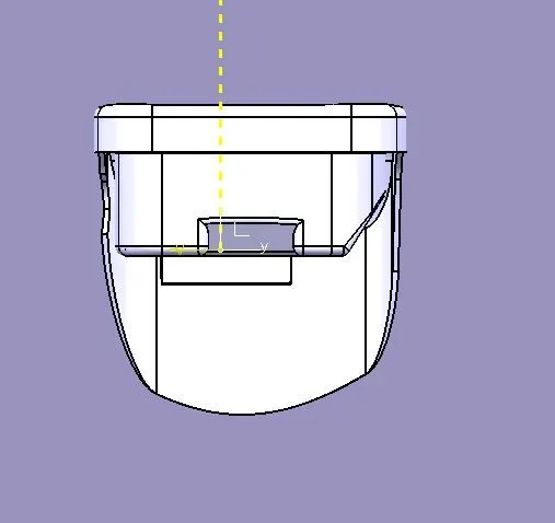
Side view
Top view