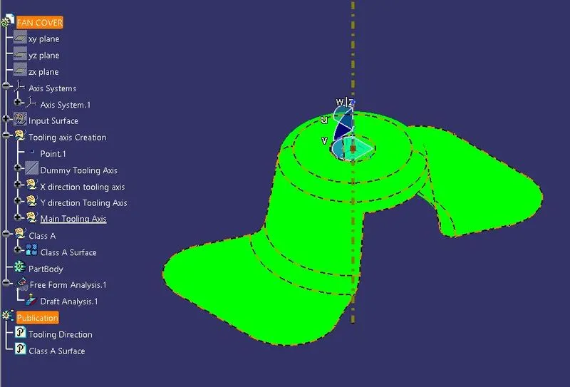
Week 8 - Challenge 1 - Draft Analysis on a Fan Cover
Objective:-
Creating tooling axis for the given model (Fan cover) meeting the requirement of draft angle and draft analysis.
Detailed Report:-
1.Checking the continuity of the given class A surface model
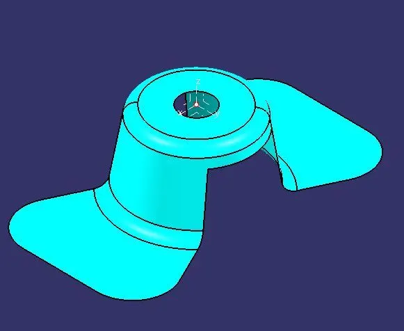
First of we have check the continuity of the given class A model through the boundary or join command. This operation perform to check the all the surface is properly join or not? Here green line shows the closed boundary it means the given surface is closed surface.
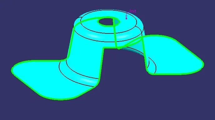
A seperated image of closed boundry inserted below.
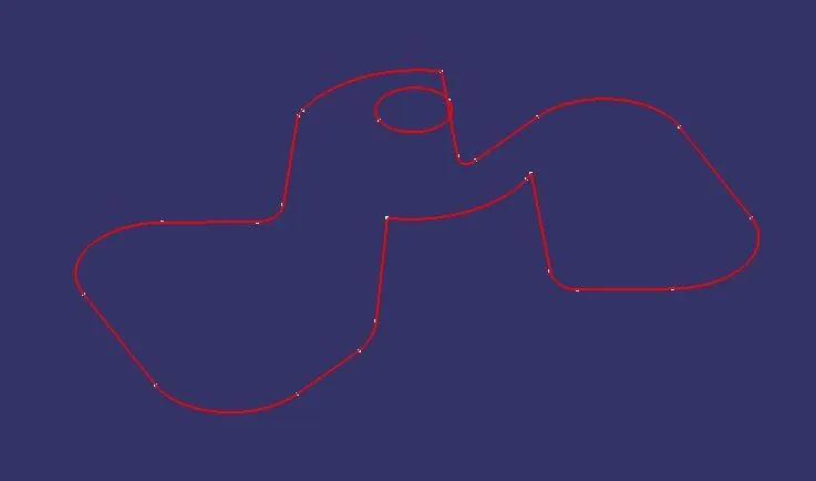
2.Tooling axis direction
Tooling axis is that direction where mould open & closed on injection mould machine. Every mould have only one main tooling axis. So visually we inspect the tooling axis to reduce the cost of the tooling for which avoid unnecessary defect.
In the this picture if we choose X- direction is a tooling direction then top hole creating a problem for which we additional use some mechanism like slider for which mould cost increase and also increase the possibiity of defects.
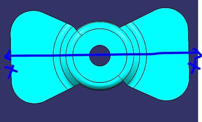
In Y-direction same problem occurs which occurs in X-direction.
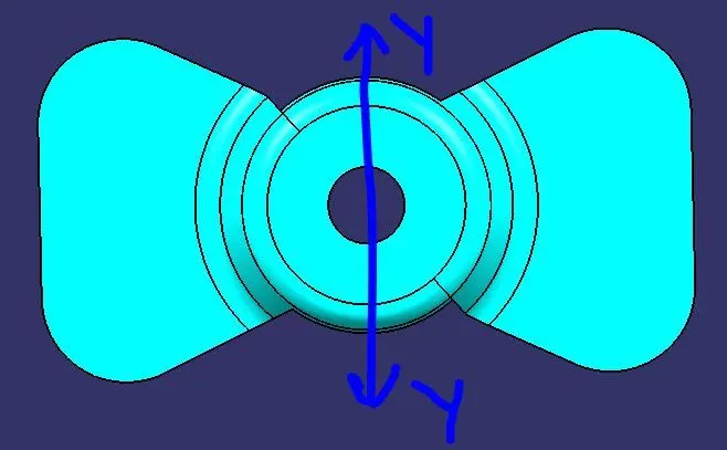
In Z-direction there is good possibility to choose the tooling axis which minimise the tooling cost and also reduce the molding defect after core and cavity matching.
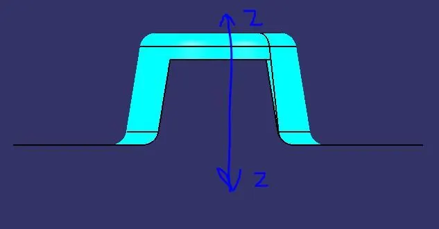
After deciding the tooling axis we create tooling axis.
3.Creating a dummy tooling axis
We have create a dummy tooling axis to visualize the mould direction roughfly. First we cteate the point with the help of given class A surface on the top of the hole.
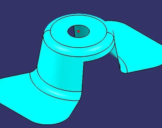
After that we create a dummt tooling line with the help of line command. the orange colour show the dummy tooling axis along Z-Direaction
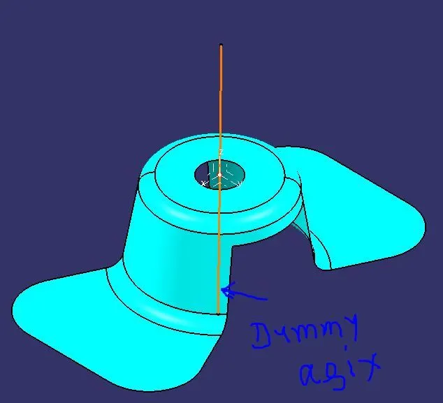
4.Create axis system
We create a axis system on the create point through axis command make sure that the current feature is uncheck. For this axis system we create intersection curve on differnernt plane to create the tooling axis.
5.Create tooling axis
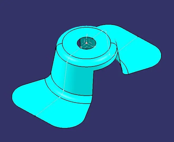
To create tooling axis first we intersect the class a surface to Z-X plane with the help of intersectrion command.The white colour line show the intersection curve of Class A surace to Z-X plane.
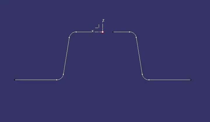
Now Create line through point to point as the given image below.
This yellow colour show the Line through point to point.
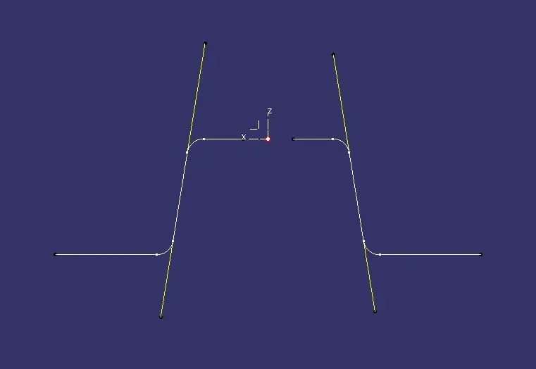
The Green colour line shoew the bisecting line of both both yellow line which the tooling direction along the Z-X plane.
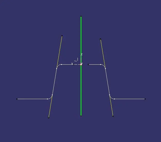
Create the interction line between class A surface and Y-Z plane thorough intersection command which show below in brown colour
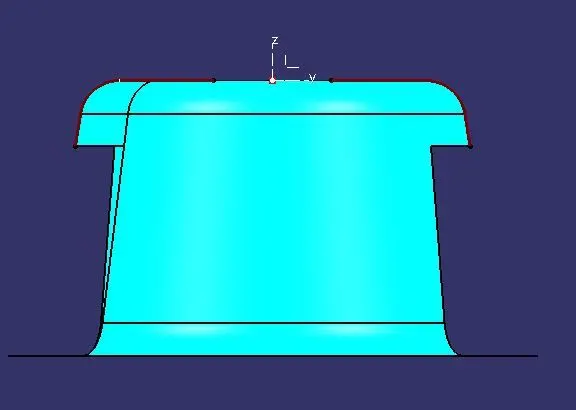
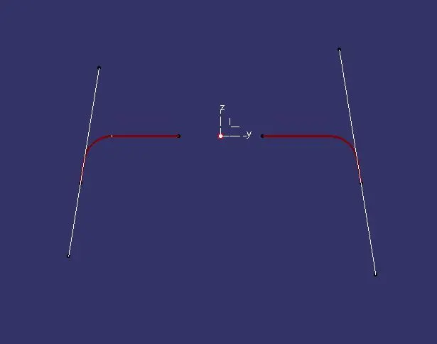
Create the line through point to point with the help of line command. this line show below in white colour.
create a bisecting line the above white colour line. this bisecting line show below in blue colour.
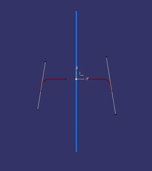
This image show the how to create bisecting line under the line command. In below image we choose line type as a bisecting then we choose both line and set the point from where bisecting line passes and then choose the support direction (Choose that direction where we have required the direction).
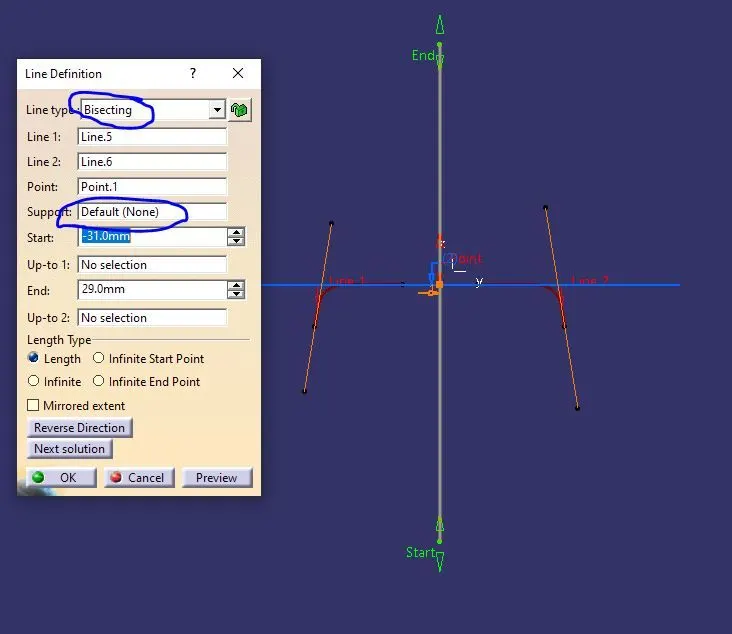
We have create two bisectiong line with the help of intersetion curve which is on x-z plane and y-z plane, Now from this two bisectiong line we again use bisectiong line which show in the below image. this bisection line is the main tooling axis of the mould where fix half and movige half slide.
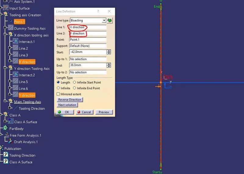
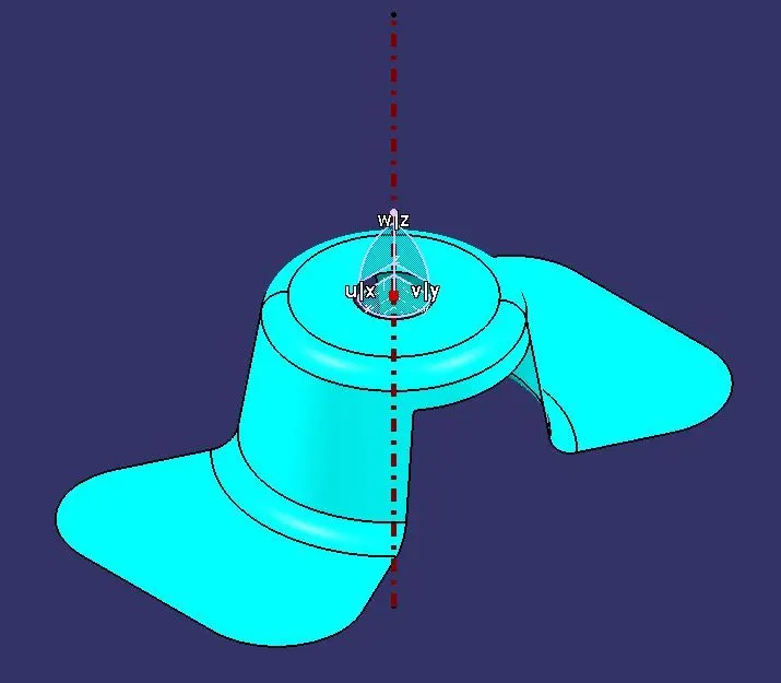
The Brown colour shows the main tooling axis.
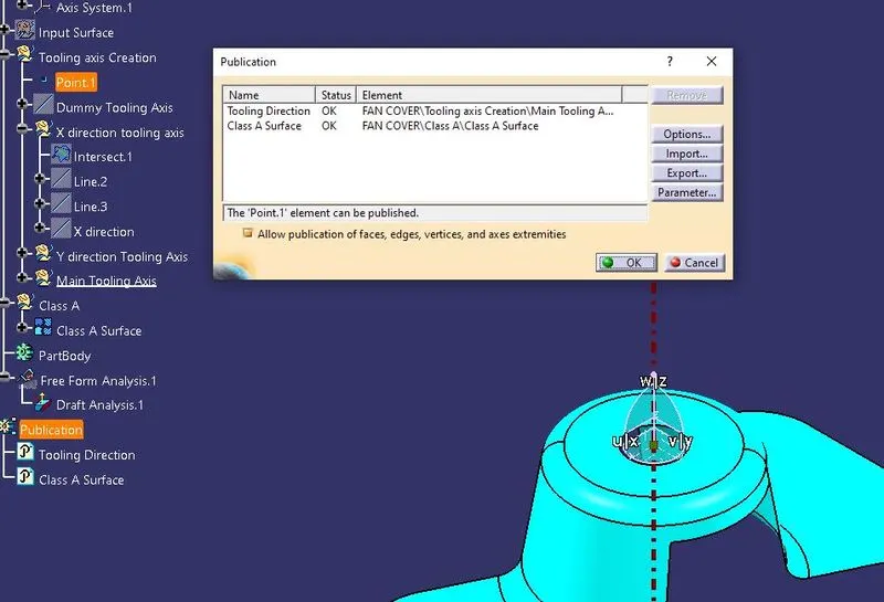
We publish the class A surcace as well as tooling direction
Select Class A & tooling Direction then go to tool option in the bottom last choose publish.
5.To perform Draft analysis
Go to insert>analysis>feature draft analysis
First changing the view mode as a material mode.
In draft anaysis command click the comapass then choose the double click the compass bottom rectangular point (Situated on the upper right corner) and place it along the tooling axis,lock the compass after that now click on the surface after that surface colour change.
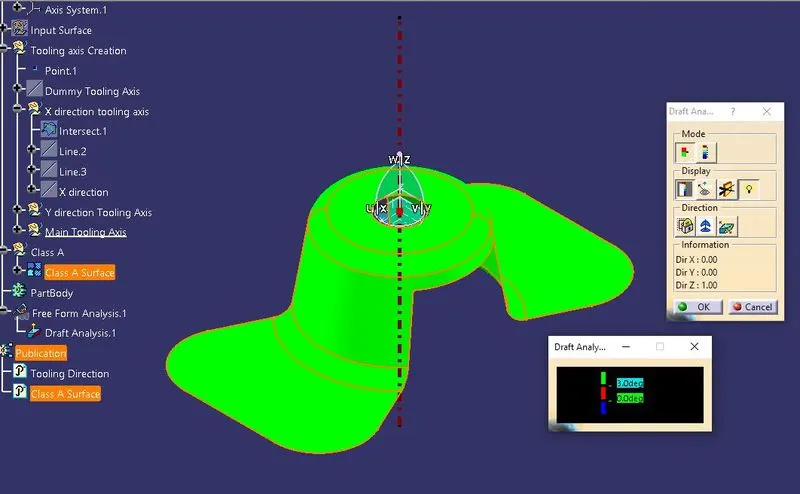
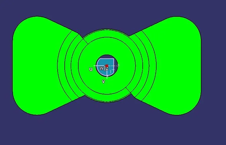
This green colour shows the cavity direction. in the draft analysi colour it shows green colour on 3 degree draft which is suitable for automotive industry.
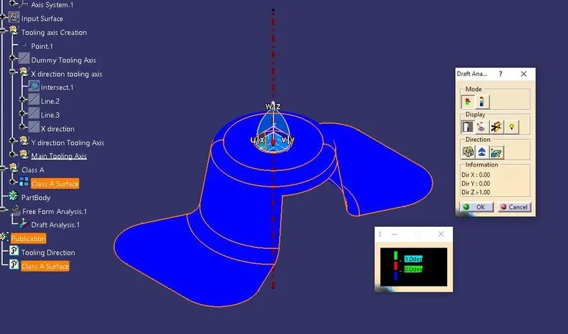
After clicking on reverse direction we can change direction of tooling.
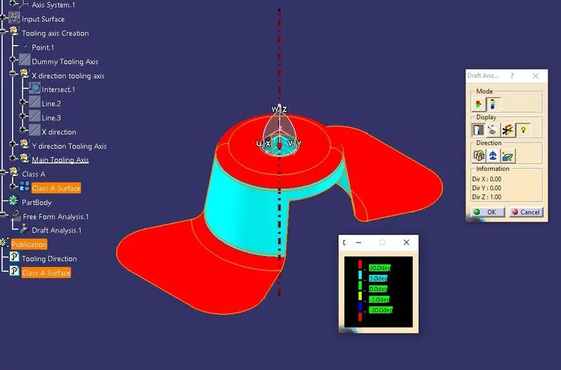
Now we change the mode for which deatialed draft show on every faces. The below image shows different draft on different faces.
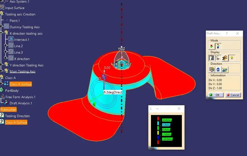
This is the draft running point for which we see the draft angle on different faces through running method.
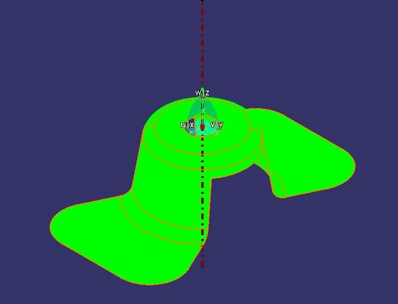
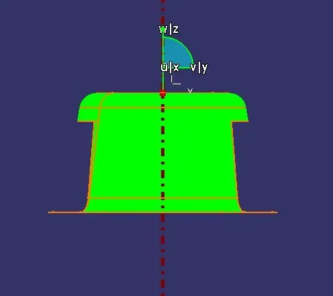
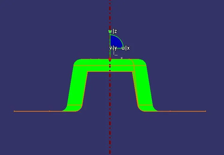
The different type of view of draft analysis of fan cover.
Isometric view
Front View
Side view
Top View
Deatiiled tree structre of draft analysi of Fan Cover body