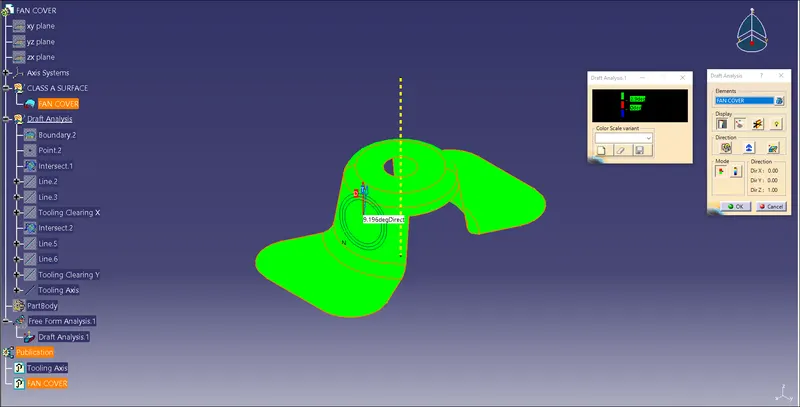
Draft Analysis on a Fan Cover
Aim: To create the tooling Axis for the given Fan Cover Model and to perform the Draft Analysis on the model in CATIA V5.
Need for Draft Analysis:
When developing parts for plastic injection molding, applying a draft (or a taper) to the faces of the part is critical to improving the moldability of your part. Without it, parts run the risk of poor cosmetic finishes and may bend, break, or warp due to molding stresses caused by the plastic cooling. Equally important, an absence of draft may prevent parts from ejecting from the mold, damaging not only the parts but possibly the mold itself—a costly and time-consuming detour.
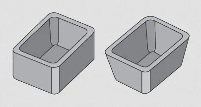
Draft Early
Ignoring draft early in the design process is a common mistake that occurs when prototyping with 3D printing and CNC machining processes where the draft is not required. Because of the layer-by-layer method in which 3D-printed parts are built, nearly any design can be produced with limited concern for moldability. The same can be said for machined parts as part ejection is purely a molding consideration.
But if a prototype design will eventually move to injection molding, it is befitting to design draft into parts from the very beginning. The draft may alter the form and fit of a part during assembly and its overall aesthetic, so designing in the draft, even when it’s not technically needed, can help you avoid any surprises such as costly redesigns and additional prototype development.
Design for the future need, not the current need. When the part is ready to move from 3D printing or machining into injection molding with the draft already integrated, the design is accelerated and production can begin sooner. Don’t print or machine yourself into a corner by manufacturing a product that needs more design work before it can be molded.
Follow the Rules
The truth is no single draft angle can be applied to all part designs. Factors like wall thickness, material selection, ejection, shrink rates, finish/texture, wall depth, and manufacturing capabilities all come into play. But fear not, there are some simple rules that can be followed that can help.
When designing a part, apply as much draft angle as possible—a general rule of thumb is 1 degree of draft per 1 inch of cavity depth, but that can change with the aforementioned factors. Try following these general guidelines:
- 0.5 degrees on all vertical faces is strongly advised.
- 1 to 2 degrees works very well in most situations.
- 3 degrees is minimum for a shutoff (metal sliding on metal).
- 3 degrees is required for light texture.
- 5 or more degrees is required for heavy texture.
Methodology:
Creation of Tooling Axis:
In this example, a fan cover is taken for draft analysis. Click here to download the CATPART.
First of all, we need to check for the boundaries in the model. Check if all the surfaces are continuous and do have any boundary between them.
Now, after this check, make sure to create a dummy tooling axis in the z-direction. (In this example we are taking a dummy in the z-axis, it can be taken in any direction based on the shape of the model.)
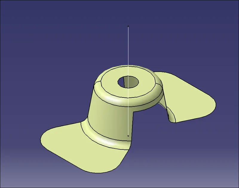
Fig. Dummy tooling Axis
After this create the tooling clearing in the X-direction. For this, we need the 2D sketch of the fan cover as viewed from the X-direction. For this use the intersect operation and choose the ZX plane from the axis system as the first element and fan cover surface as the second sketch.
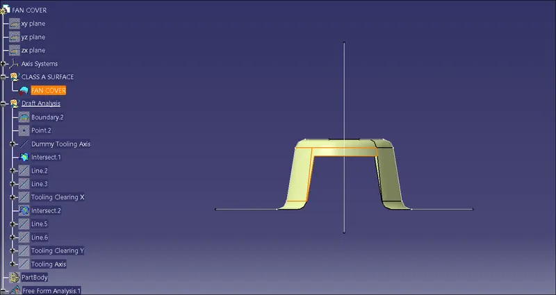
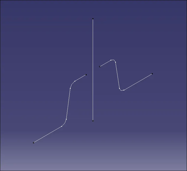
After this create two lines representing the walls of the fan cover and then create an axis clearing in x-direction bisecting these lines.
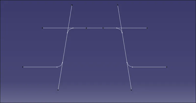
Follow the same steps to create a tooling axis clearing y-direction.
And using these two lines as a reference creates the main tooling axis.
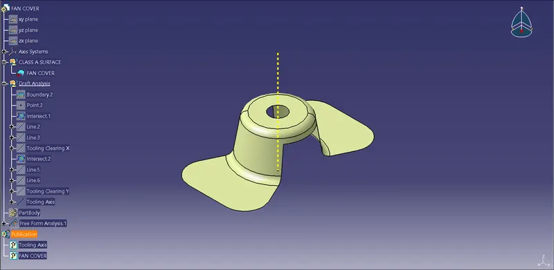
Draft Analysis:
- To perform the draft analysis go to the Featured Draft Analysis tool.
- Now, align the compass's z-direction with the tooling axis which we created in the previous steps.
- Now, open the color scale and enter the value as 2.9 deg.
- Now hover the cursor over the body to check if every face has an angle greater than the given angle.
- Also, if the whole body is in green color it means that the value at all the faces is greater than the provided angle.