Week 8 - Challenge 1 - Draft Analysis on a Fan Cover
Draft Analysis on a Fan Cover
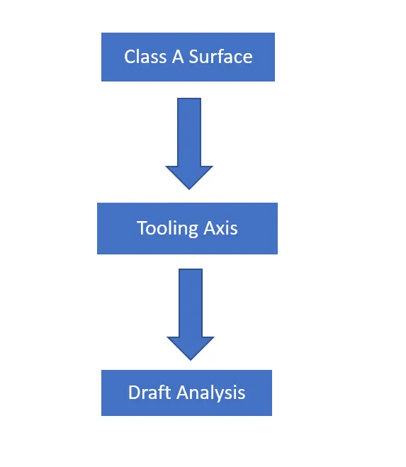
Aim: To create the tooling axis for the given fan cover model and then perform draft analysis meeting the requirement of the draft angle.
Introduction:
Class A Surface:
In automotive design, a class A surface is any of a set of freeform surfaces of high efficiency and quality. Although, strictly, it is nothing more than saying the surfaces have curvature and tangency alignment to ideal aesthetical reflection quality, many people interpret class A surfaces to have G2 (or even G3) curvature continuity to one another.
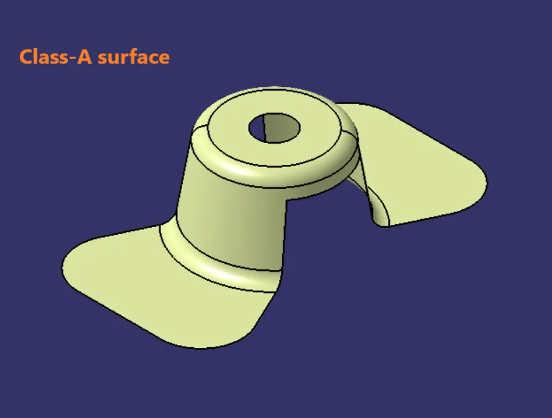
Class A surfacing is done using computer-aided industrial design applications. Class A surface modellers are also called ‘digital sculptures’ in the industry. Industrial designers develop their design styling through the A surface, the physical surface the end user can feel, touch, see etc.
Tooling Axis:
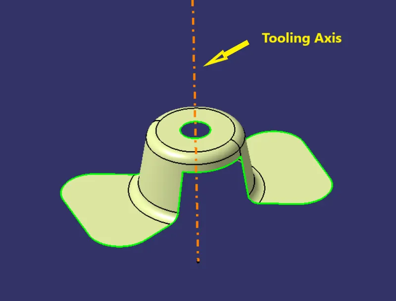
Tooling axis is the direction in which the mold or core and cavity opens.
Draft:
Draft is the angle in which the part is tapered to allow it to release. As the part cools, it tends to shrink to the core side of the mold. Draft is required on all parts in the direction of mold movement in order to allow parts to release or eject from the mold properly.
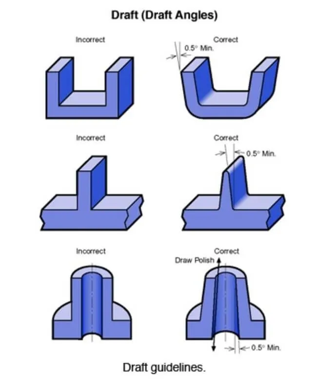
Most parts or applications require a minimum of 0.5 to 1 degree, however 3 degree is widely accepted as normal.
Draft Analysis:
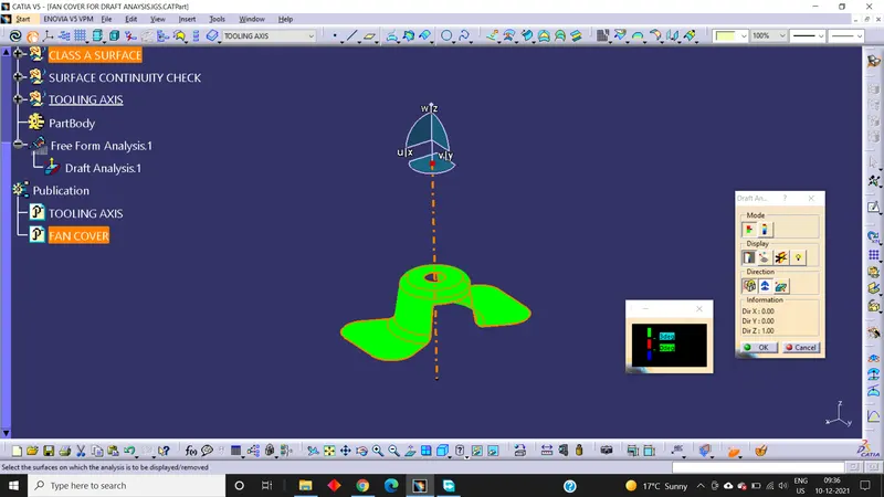
Draft analysis is done in order to detect if the part that has been drafted will be easily removed or not. This type of analysis is performed based on the colour ranges identifying zones on the analyzed elements where the deviation from the draft direction at any point corresponds to the specified values. When the draft analysis passes, it means our part is easily toolable or can be easily ejected.
Procedure:
Step 1:
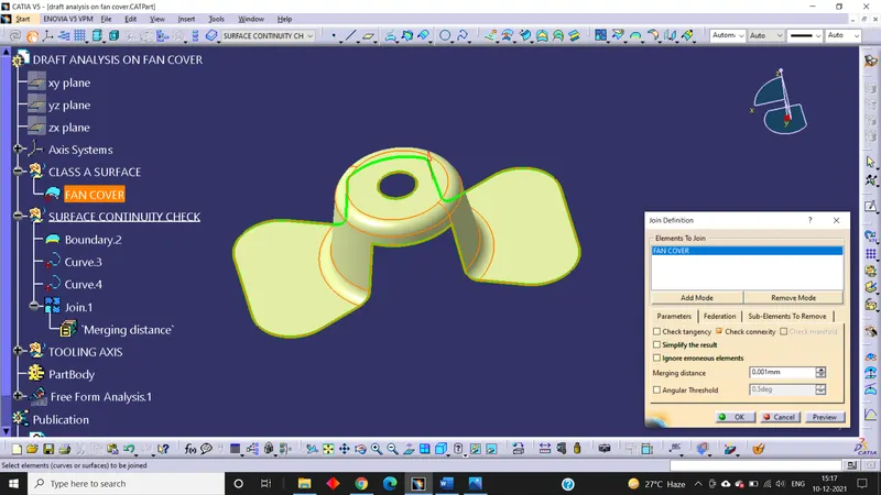
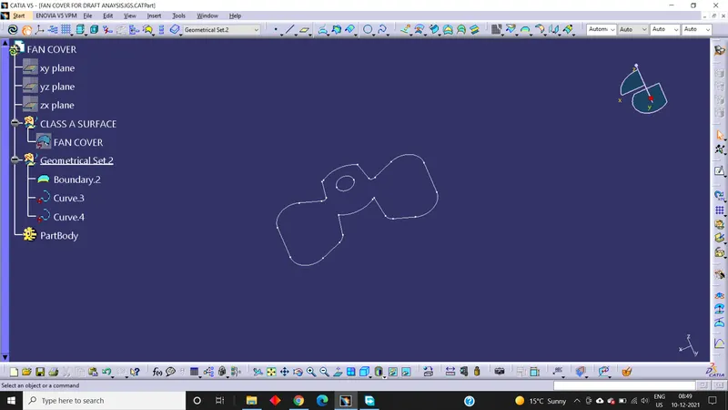
After getting the Class A Surface from the styling team, we have to ensure that the Class a Surface is properly joined and has no discontinuity on it. To check that we have to use the Boundary command or Join command.
Join:
Boundary:
Step 2:
After checking the continuity of the Class a Surface, we have to analyse manually or visually to see which is the proper direction for the Tooling Axis.
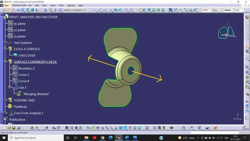
In the X-direction, it is difficult to clear the top hole and the side slots on both sides.
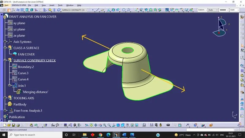
In the Y-direction also the top hole is not clearing. So we look into the Z-direction.
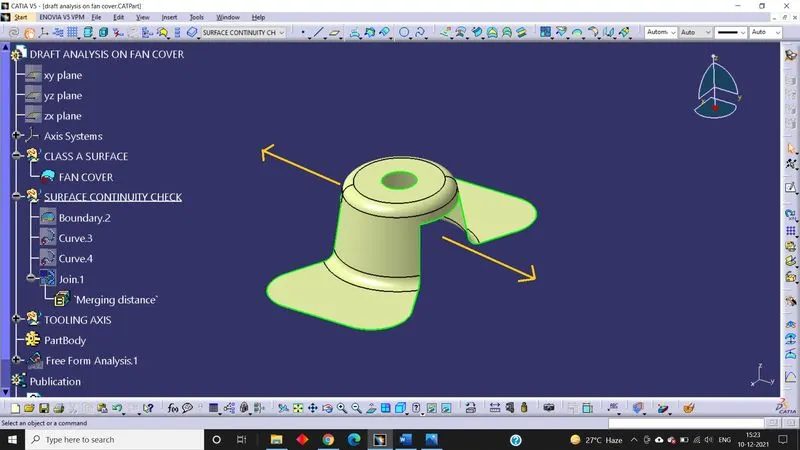
In Z-direction, it is possible for the mould to open easily as it is clearing the top hole as well as the side slots.
Step 3:
After that we create a dummy tooling axis.
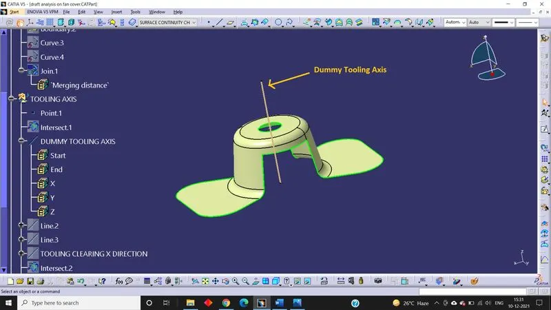
Step 4: Now we use bisecting line method to create the real tooling axis.
Bisecting line concept:
Tooling Clearing X-Direction;
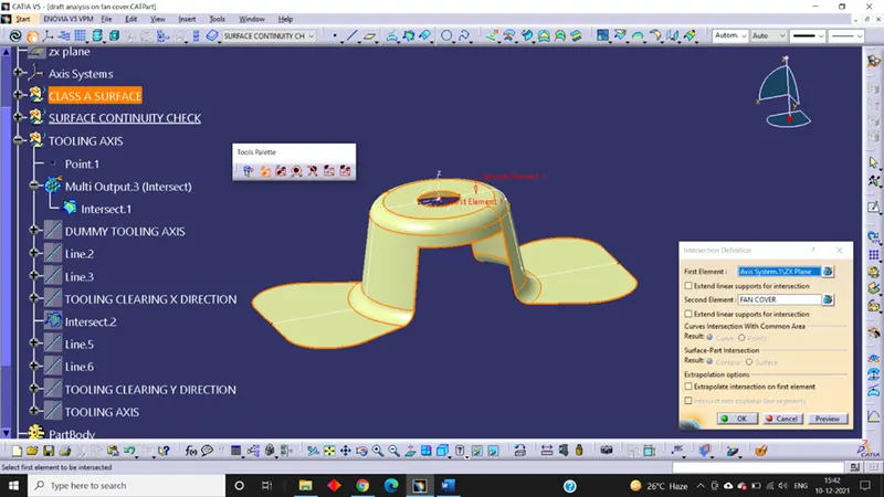
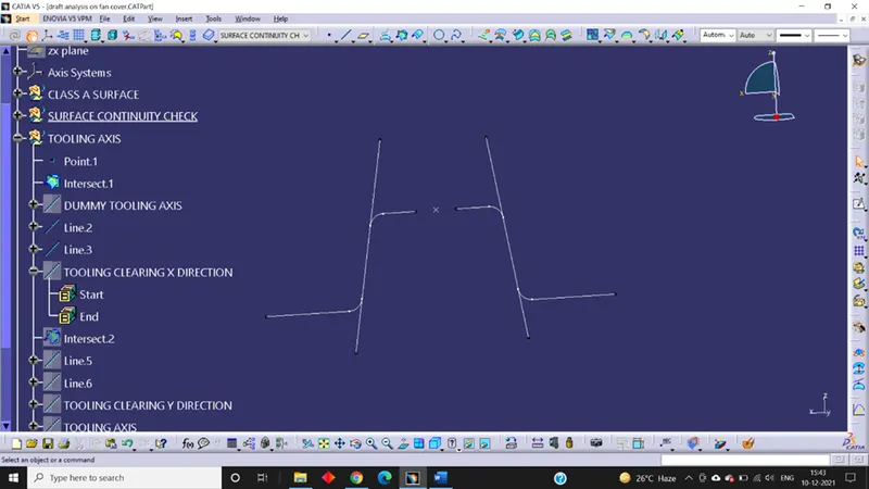
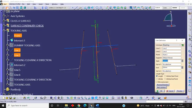
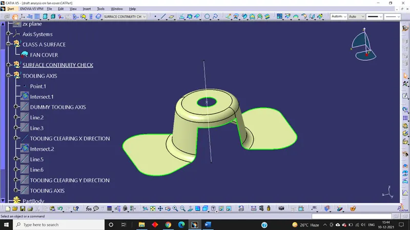
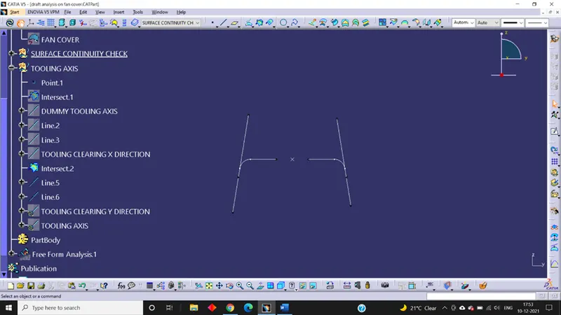
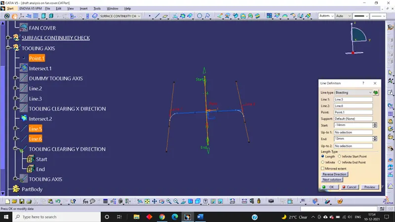
Here we create an axis system and intersect the ZX plane with the Class A Surface. After that we choose those surface which create problems or difficult to be tooled and create a line using point to point option on both sides and then create a bisecting line using the previously created lines. This will be our tooling axis which clears the X-direction.
Tooling Clearing Y-Direction;
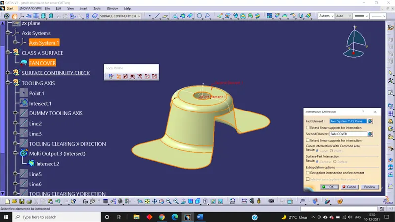
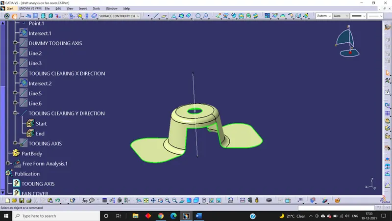
In the same way, we intersect the YZ plane of the axis system created before with the Class A Surface and the repeat the same procedure as we did for the X-Direction.
Step 5:
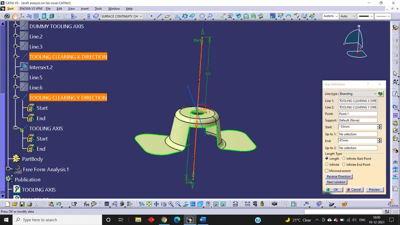
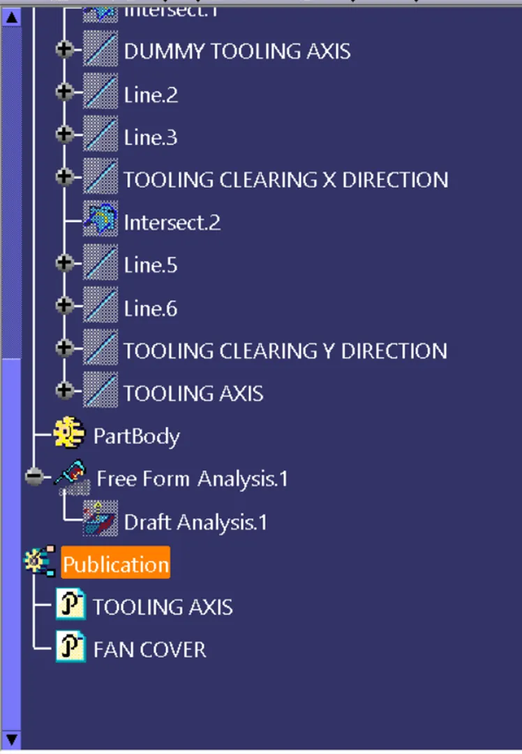
Now we have two tooling axis; axis clearing x-direction and axis clearing y-direction. So we can again use bisecting line command and get a real tooling axis from these two axis created earlier. Once the final tooling axis is created we publish the tooling axis and the Class A Surface so that it is easily pickable whenever required as we work on further.
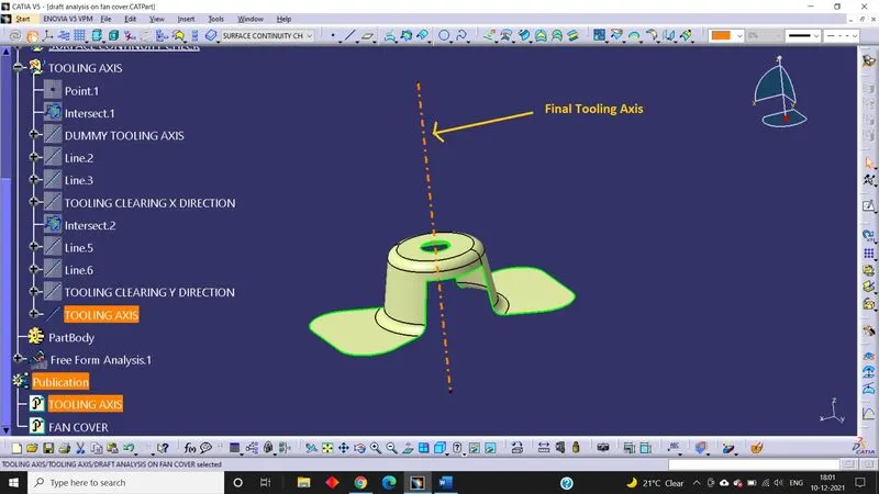
Step 6:
Draft Analysis
First of all we change the view mode to the Customize View Parameters and ensure that the material mode is checked as shown below.
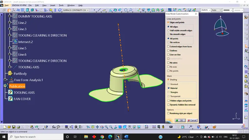
Step 7: After that we will go to the draft analysis command and open it then the draft analysis display appears.
Here we work on the quick analysis mode.
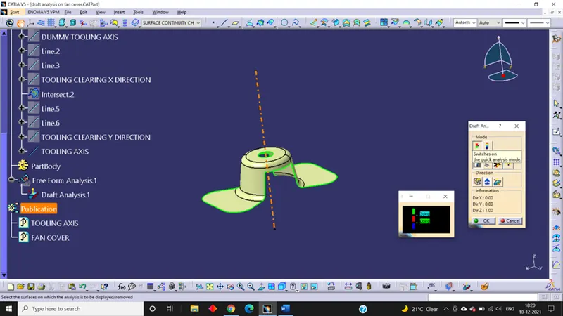
Then we click on the compass icon in the display and then we will align the compass in the window screen with the tooling axis.
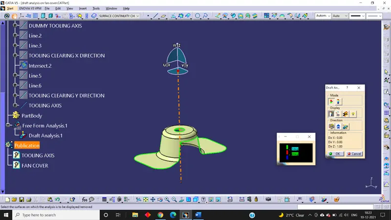
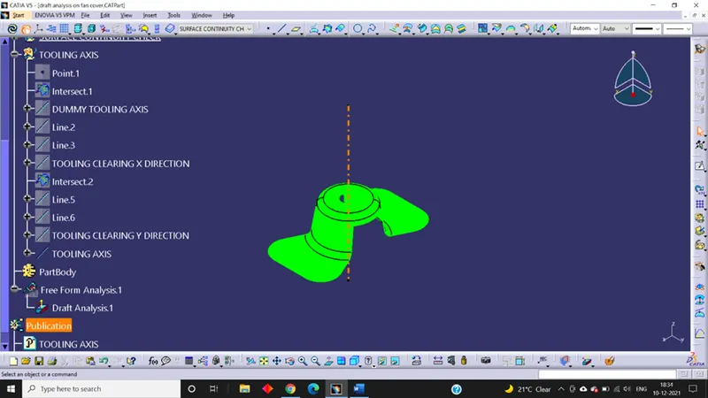
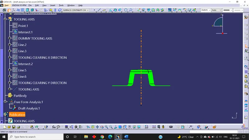
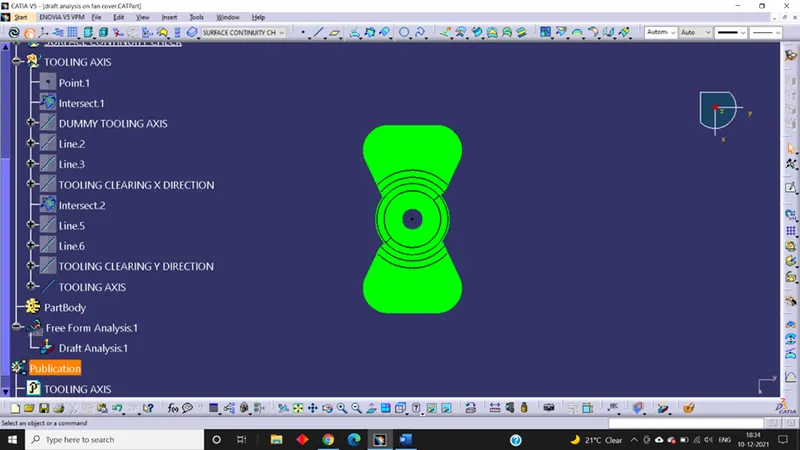
Step 8: After that when we move the mouse cursor on the Class A Surface then a cross sign is shown and then we have to click on the Class A Surface. Finally, the Class A Surface changes its colour to green. We have taken the draft value for this component is 3 degree.
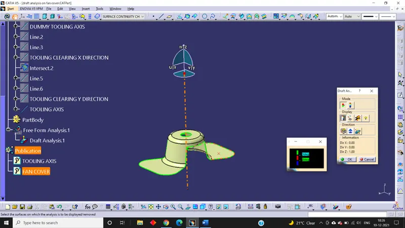
Complete Draft Analysis:
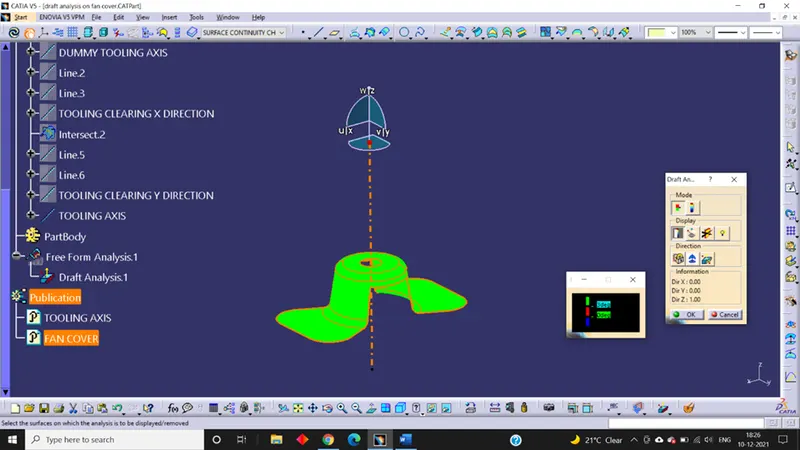
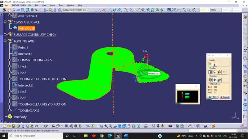
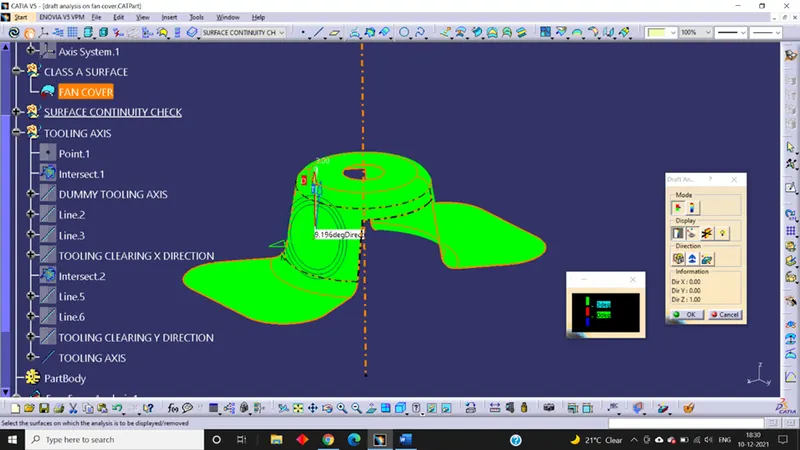
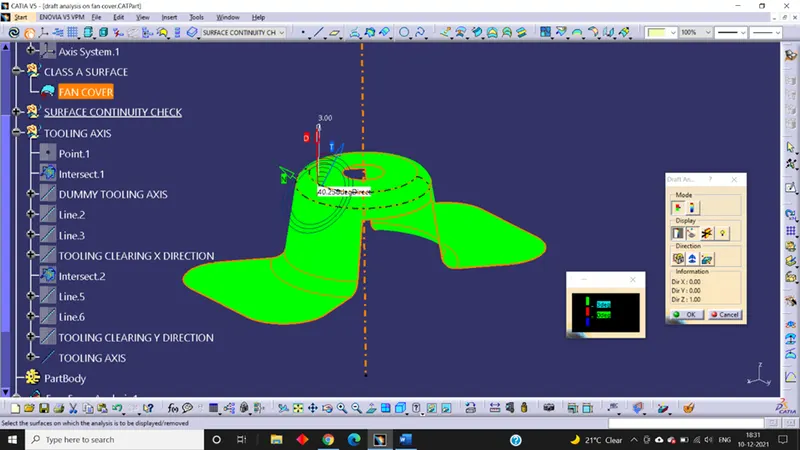
Color Scale Variant:
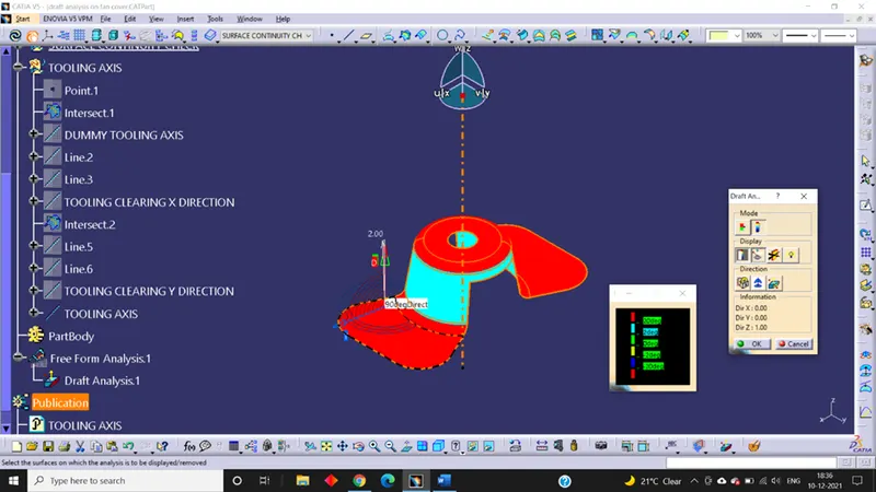
Isometric View:
Front View:
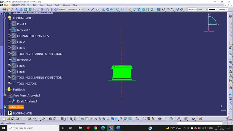
Side View:
Top View:
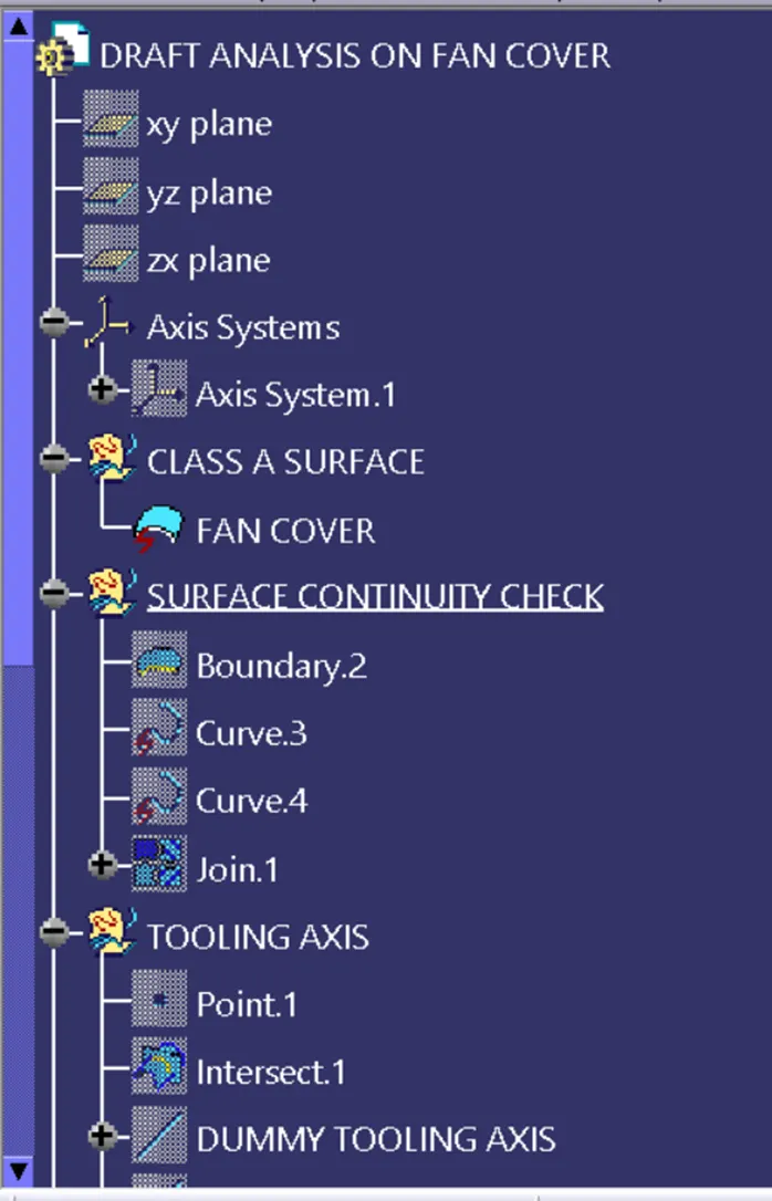
Tree Structure with Publication:
Conclusion:
The tooling axis was created for the given Fan Cover and draft analysis was performed for the required draft angle.