Week 8 - Challenge 1 - Draft Analysis on a Fan Cover
Draft Analysis on a Fan Cover (Challenge - 1)
What is Generative Shape Design?
The Generative Shape Design provides an extensive set of tools for creating and modifying mechanical surfaces used in the design of complex shapes or hybrid parts, its feature-based approach offers a productive and intuitive design environment to capture and reuse design methodologies and specifications. It helps to design advanced shapes that are based on a combination of wireframe and extensive multiple surfaces which includes high-level features with full specification capture and reuse.
What is Draft Analysis?
The Draft Analysis command enables you to detect if the part of you drafted will be easily removed, this type of analysis is performed based on color images identifying zones on the analyzed element where the deviation from the draft direction at any point corresponds to specified values.
No parts can be ejected from the tool if it is having a straight 90-degree profile from its base surface, a small draft angle is provided to each and every area of the component in order to get easy removal of the component from the tool. Draft analysis technique is used to analyze whether our part model created in cad is manufacturable based on the draft condition applied.
In the molding process the molded parts have to eject from the die so there are some issues while removing the molded parts it may get sticky with the die, or while removing the chances to get damaged, so we need to set up is the draft angle this draft angle helps the molded part to eject from the die easily.
On what type of components, we perform Draft Analysis?
Draft analysis is performed on the components where the ejection of material happens after the material is made inside of the tools. In case of Automotive Sheet Metal manufacturing, the blank sheet after turning into automotive panels like Hood, Fender, Roof, Doors etc. needs to be removed from Panel Dies, if a considerable amount of draft angle is not provided, the removal components from the tools will be difficult. Same in the case of mold (plastic component) after getting filled inside the core and cavity, it needs to get ejected easily with the help of ejectors.
What factors should be considered while doing the draft analysis for the Plastic/Automotive Sheet Metal parts?
The major consideration of Draft Analysis whether sufficient Draft Angle is provided on the Component. Components while designing should be provided with a considerable amount of draft angle depending on the manufacturing consideration. For plastic component we provide a draft angle of 3 degree (Draft angle of 0.5 is given ideally to the features inside the plastics part), but for the Automotive sheet metal parts it will be from 7 degrees or more.
** Draft angle of 0.5 is given to the Rib feature on plastic parts**
What are OEM Rules for Draft Analysis?
There is no such thing as a single draft angle applied along the whole model or all of the part designs, factors such as wall thickness, material selection, ejection, shrink rates, finish /texture, wall depth, and manufacturing capabilities all come into play.
There are simple rules that when followed might help you get a proper draft angle:
- 5 degrees on all vertical faces is strongly advised.
- 1 to 2 degree works very well in most situations.
- 3 degree is minimum for a shutoff (metal sliding on metal).
- 3 degree is required for light texture.
- 5 or more degrees is required for heavy texture.
Procedure for Draft Axis
- Check the connectivity to Class A surface model.
- Defining point as Circle point type.
- Create dummy axis tool at the point as the Z direction.
- Create Axis system at point 1.
- Intersect the model ZX of Axis System 1.
- Create two point-to-point lines which inclined towards the dummy axis tool.
- Create Bisecting line with reference of two line and point 1.
- Edit line color and thickness and assume as X tooling Axis.
- Intersect the model with YZ of Axis System 1.
- Create two point-to-point lines which inclined towards the dummy axis tool.
- Create Bisecting line with reference of two lines and point 1.
- Edit the color and thickness and assume as Y tooling Axis.
- Create Bisecting line with reference of X tooling axis, and point 1 for Main tooling Axis.
- Publication Main tooling and Class A surface model of Fan Cover.
- Select View mode and select material as shading.
- Lastly, select Feature Draft Analysis and procedure.
Methodology for finding Draft Axis and the Draft Analysis
- Connectivity Check
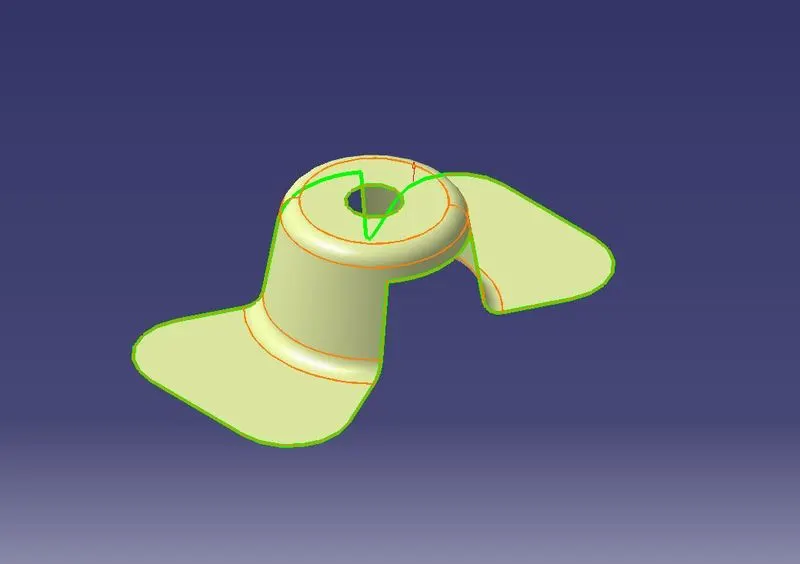
Firstly, we have to check the continuity of the given class A surface to ensure are Class A surface is properly joined or no discontinuity present, this can be done using the join or boundary command in CATIA. Visual representation is shown below
- Dummy Tooling Axis
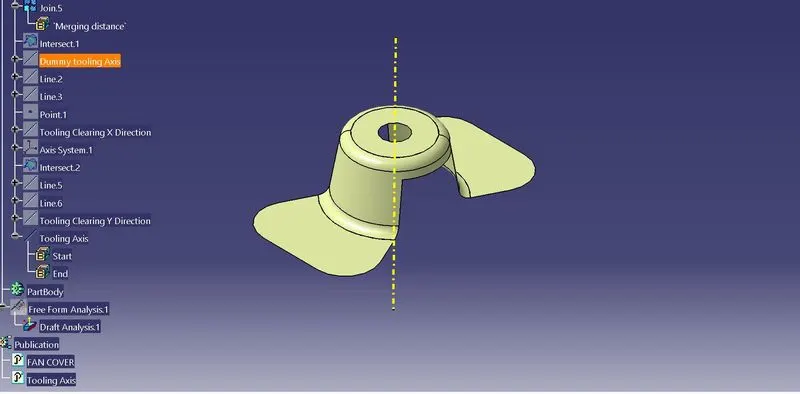
To create a dummy tool axis, create a line with point 1 and X- direction
- Creation of Tooling Axis
The tooling axis is used in the draft analysis, it is important to select the right axis for tooling considering the ejection of part from the mold, the next step is to decide the tooling axis direction. The tooling axis direction in which mold or core & cavity opens. Visual representation is shown below.
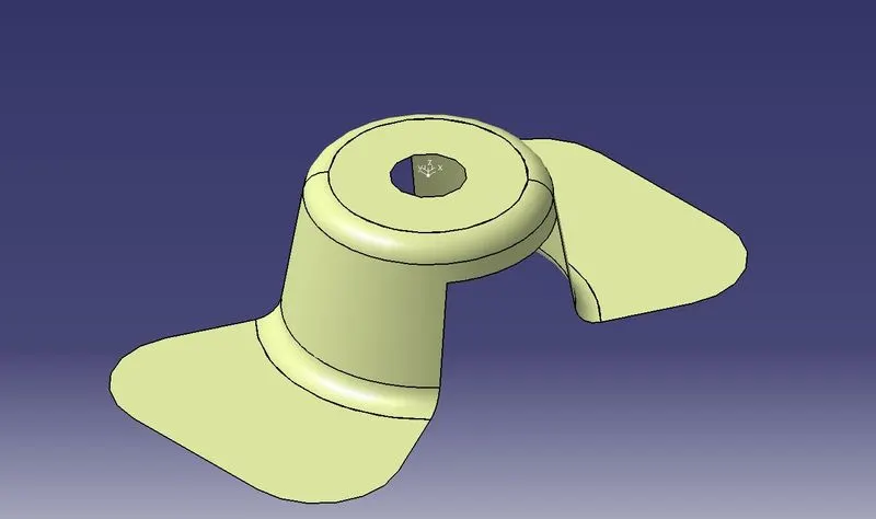
- Finding X Tooling Axis
To find the X tooling axis select the intersect option, select the ZX plane of the Axis system as the first element, and fan cover (Class A surface)
As the second element. This will give a 2D sketch of fan cover viewing from X-Direction.
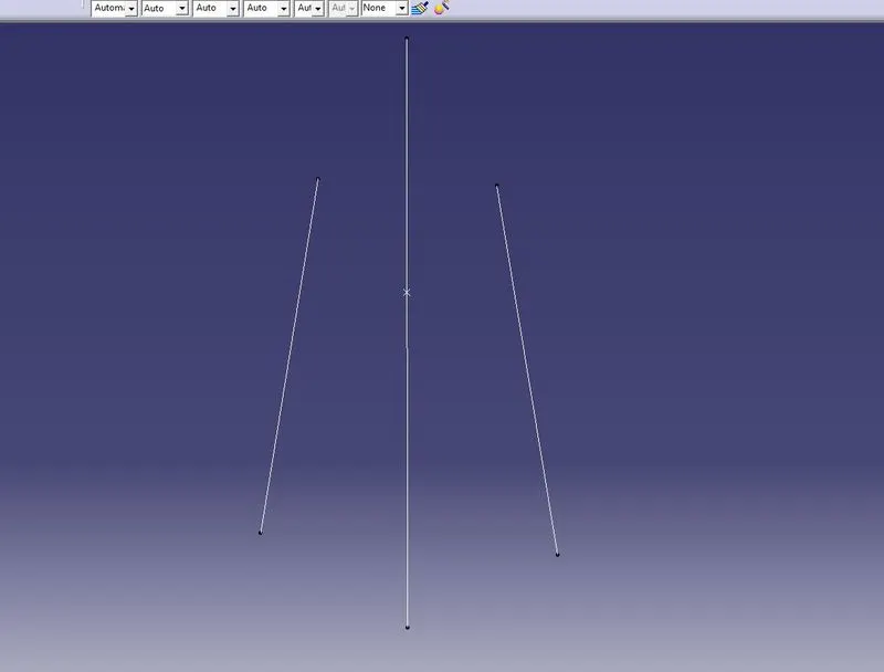
Now create lines representing the walls of fan cover using the point-to-point option with the help of intersecting. Using these 2 lines, create the tooling axis clearing X direction. Create a line that bisects these two lines from reference point in the Z direction. Visual Representation shown below of X- Tooling Axis
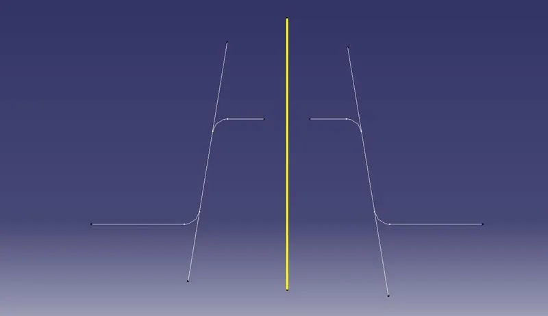
- Finding Y Tooling Axis
To find the Y tooling axis select the intersect option, select the YZ plane of the Axis system as the first element, and fan cover (Class A surface) As the second element. This will give a 2D sketch of fan cover viewing from Y-Direction.
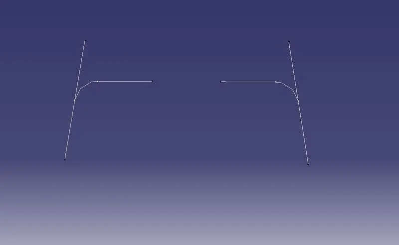
Now create lines representing the walls of fan cover using the point-to-point option with the help of intersecting. Using these 2 lines, create the tooling axis clearing Y direction. Create a line that bisects these two lines from reference point in the Z direction. Visual Representation shown below of X- Tooling Axis
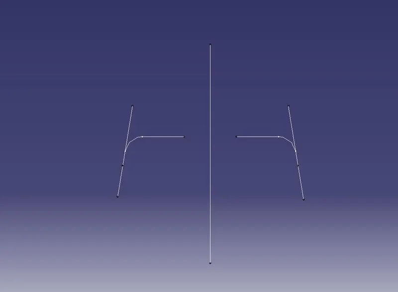
- Finding Main Draft Tooling Axis
To find the main tooling axis, create a line using bisecting option and select the “X” tooling axis as line 1, “Y” tooling axis as line 2, and Point 1 as a Reference point, Select the bisected line and change color and thickness. Visual Representation is shown below.
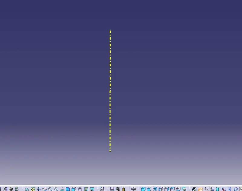
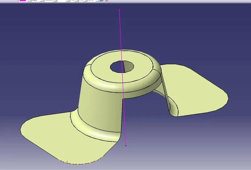
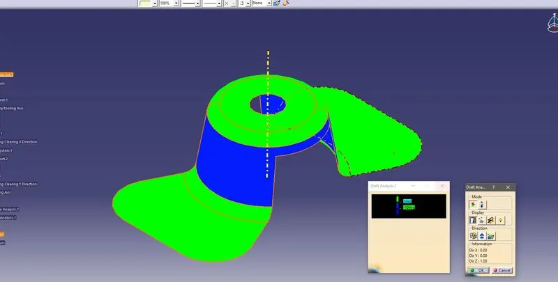
- Feature Draft Analysis
- Before performing the draft analysis, we create the Main tooling axis then the procedure.
- {Go to menu bar > select insert > Analysis> Feature Draft Analysis}.
- Now, align the compass Z-Direction with the main tooling axis which we created in the previous steps.
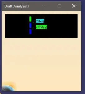
- Now, open the color scale and enter the value as 3 deg.
- Now, check if every face has an angle greater than the given angle.
- Also, if the whole body is in green color, it means that the value at all faces is greater than the provided angle.
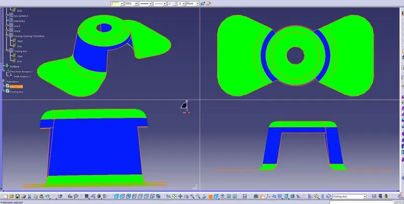
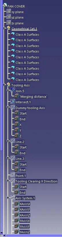
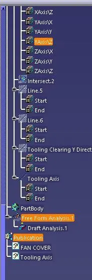
TREE STRUCTURE