Week 8 - Challenge 1 - Base Bracket Design
BASE BRACKET DESIGN:
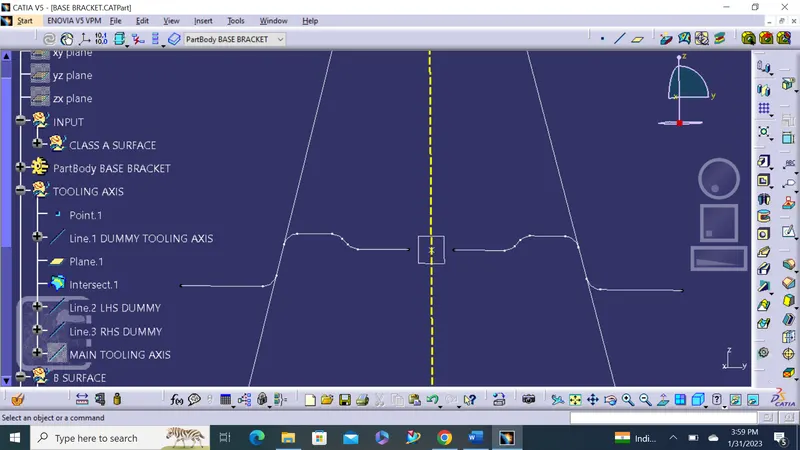
TOOLING AXIS: Where mold open & close is called tooling axis.
- Creating dummy tooling axis in Z direction based on view clearing surface.
- Dumming tooling axis created on reference of hole.
- In order avoid side core and othe creatical region of fillets.
- Intersection taken along dummy axis with help of plane.
- For clearing surface along Y direction.
- Again creating side reference line on both sides to the dummy tooling axis along intersection line.
- Bisecting both dummy tooling axis with side refrence lines to create final tooling axis.
Screenshots of Tooling axis with tree structure:
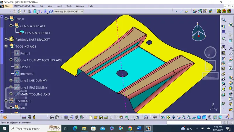
DRAFT: Draft allows for parts to release from the mold, draft is required on all parts in the direction of mold movement in order to allow parts to release or eject from mold propely.
Feature draft analysis icon:
- Modes
- Display
- Direction
Compass used to define new current draft dirction, Compass can be dragged into the tooling axis to inline.
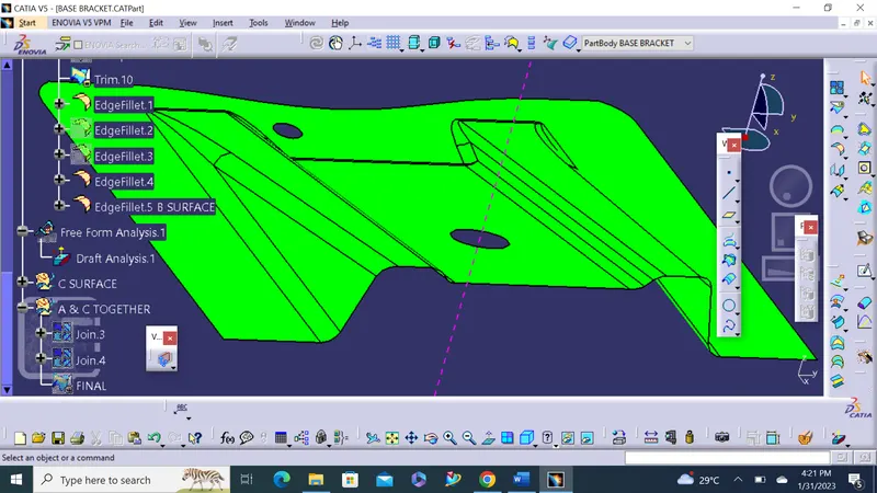
Analysis running point used to identfy critical on A SURFACE.
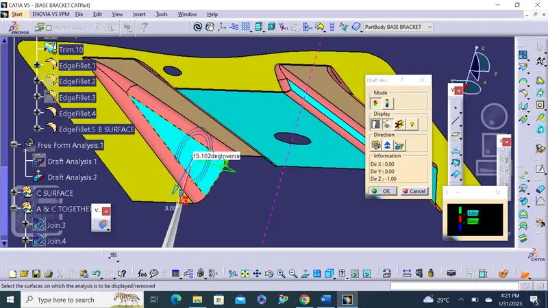
B SURFACE:
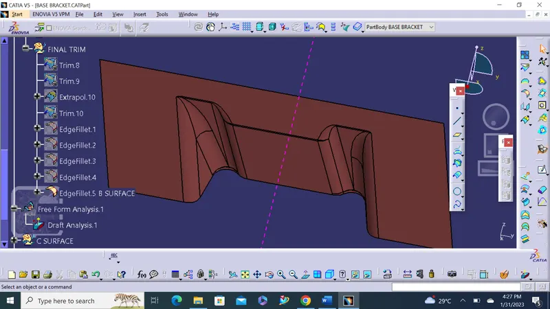
C SURFACE:
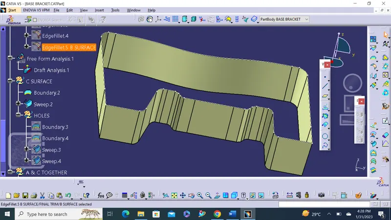
A&C SURAFCE:
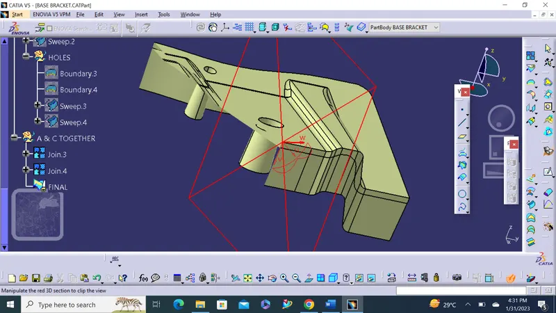
ALL SURFACE TOGETHER:
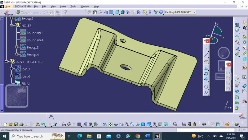
AFTER PART WORK BENCH FINAL:
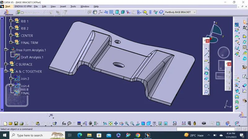
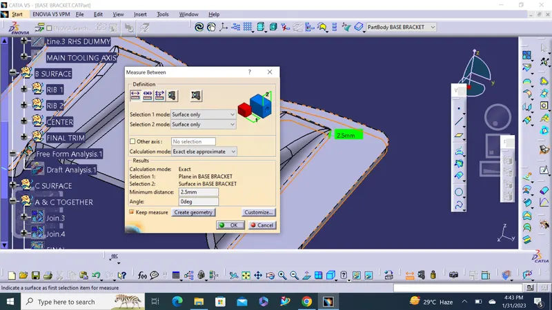
Thickness of Plastic Part - 2.5 mm