Week 8 - Challenge 1 - Base Bracket Design
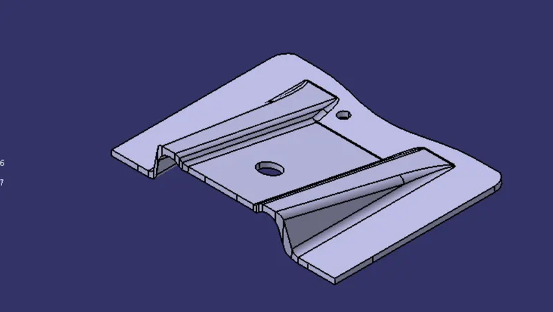
Base bracket design
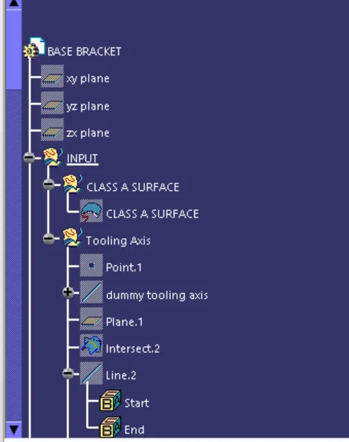
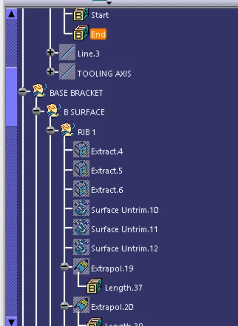
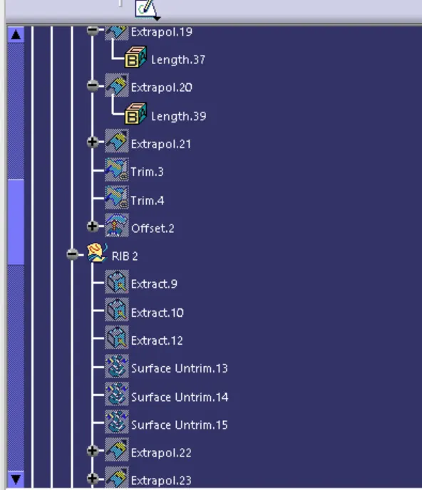
TREE STRUCTURE :
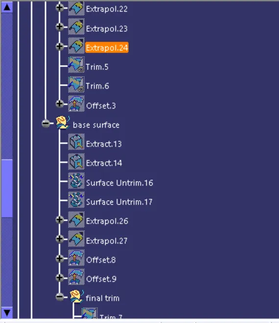
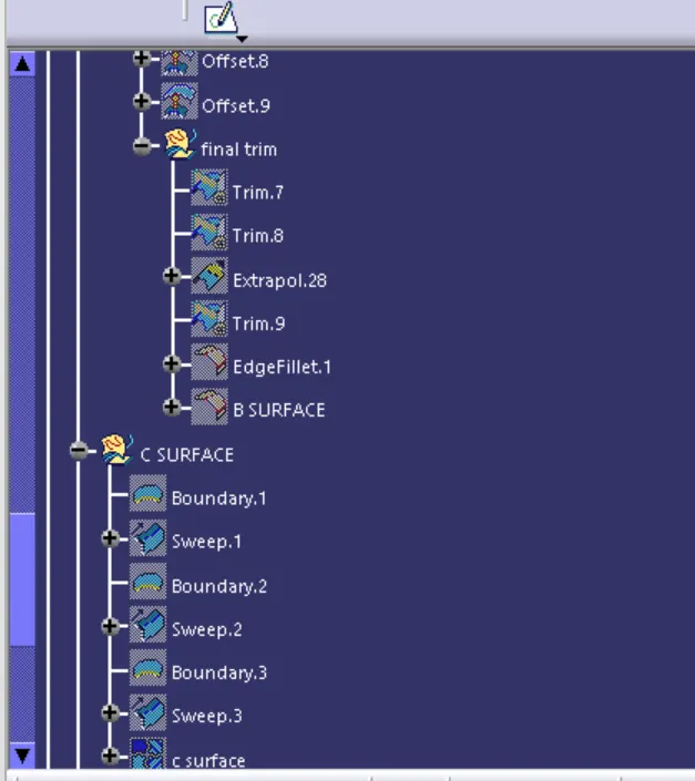
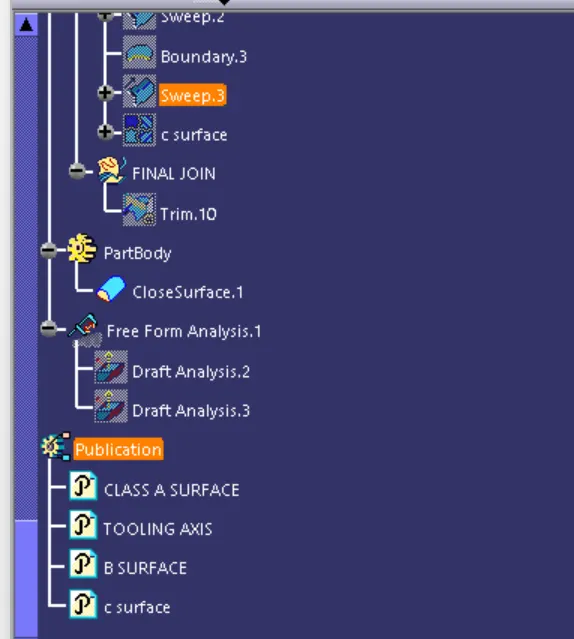
STEPS TO CREATE BASE BRACKET DESGIN
CLASS A SURFACE : It is input surface which is created on ALIAS SOFTWARE AND done by ALIAS TEAM engineer .
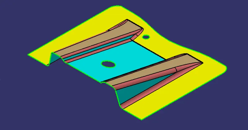
AFTER taking class A Surface we need to check if any opn boundary present OR not , if it happens then we need to join them through join command.
2. Tooling AXIS : It is those AXIS OR DIRECTION , which tells the movement of mold that is core and cavity along which direction to open .
THere are many ways to creating tooling axis
In this base bracket design i have dong through bisecting method.
In bisecting method, first i have taken the intersection of class a surface and the plane , then i have drawn the lines along the sides , and then taking the mid line of the both the lines , that mid line is becomes are tooling axis,
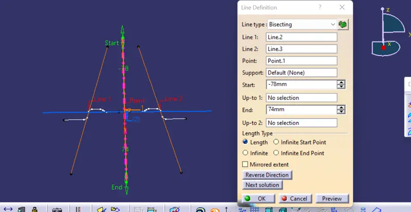
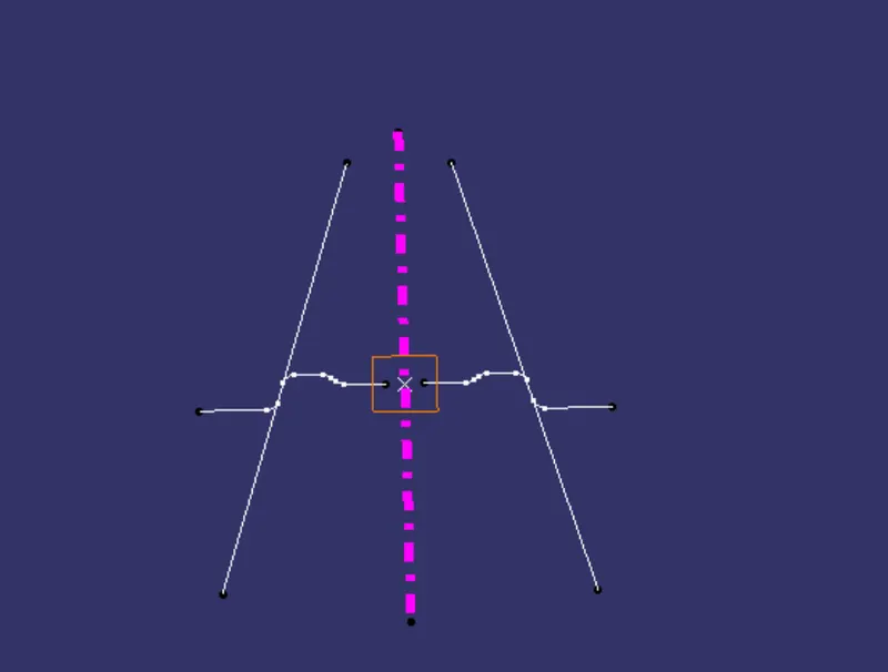
3. DRAFT analysis of CLASS A SURFACE WITH the help of tooling axis, this draft analysis will wnsure that our tooling axis which we have made right or not , which means this toolong axis will clear our part or not ,
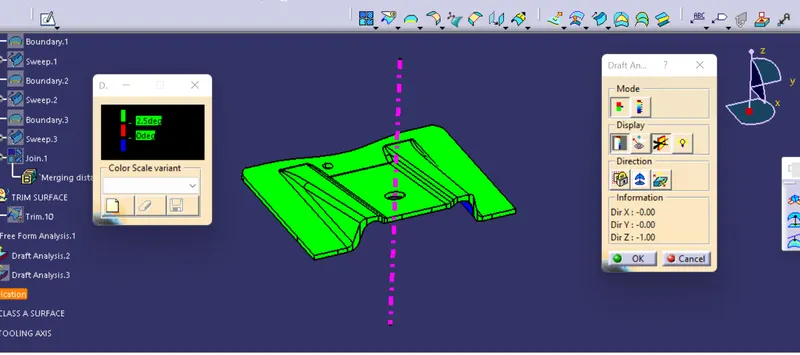
in draft analysis , basically we will evaluate the class A , that more than 3 degree draft has been provided or not . It has to be clear with more than 3 degree so that our product manufacturer will happen.
Draft analysis done by FEATURE DRAFT ANALYSIS , BY PUTTING THE COMPASS ON THE TOOLING AXIS AND THEN SELECT THE CLASS A SURFACE , HERE , After slecting the surafce , the base bracket becomes Green colour which means we can see from left side box , it shows that component is greater than 3 degree, It means our tooing direction is RIGHT.
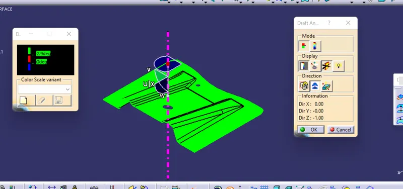
4. CLASS B SURFACE : TO make class B surafce, we need to offset the class a surface by 3mm , here , we are extract the surface first except fillet, because fillet has curvature and it does not take the appropriate curvature by offset, so we will give fillet manually and just extaract the flat surface .
B SURAFACE WILL below the class A surafce, because at the b surafce , mostly parting lines occurs , and due to that aesthetic look will not good occur at the a surafce .
steps to create the b surafce:
1. EXTRACT THE FLAT SURAFACE
2. UNTRIM THE SURFACE : It will back to previous surface whic was.
3. EXTRAPOLATE THE SURAFCE , BY taking curvature as option
4. OFFSET THE SURAFCE BY 3 mm
5. TRIM the surafce to get desired output .
6. extrapolate more if required .
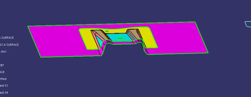
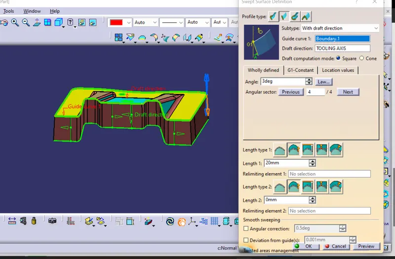
5 . class C surafce : It is surface which joins the class A AND ClassB , it is done on class A by taking taking boundary and with sweep with draft direction .
steps to create the c surafce.
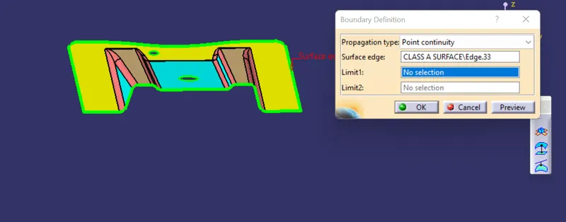
take sweep with draft direction and give 3 degree in outward direction.
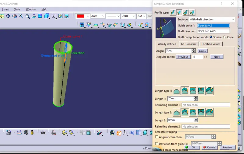
here in base bracket , we have two more holes which also need c surface , we will take boundary and sweep with draft direction 3 degree in inward direction .
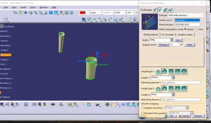
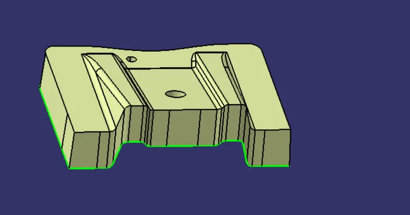
now, we will join the class A AND CLASS C SURFACE
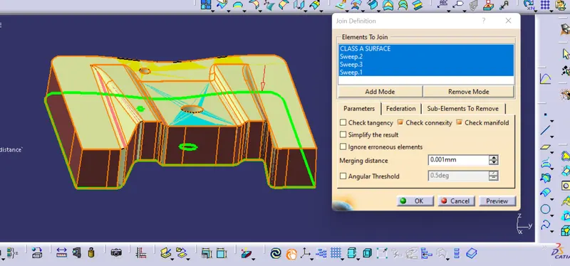
AFTER JOINING A AND C
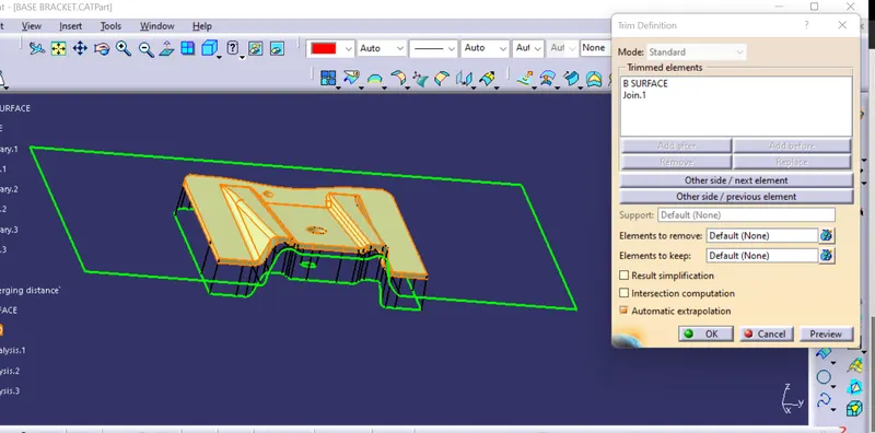
6. TRIM THE JOIN A AND C , WITH CLASS B SURFACE TO GET DESIRED OUTPUT .
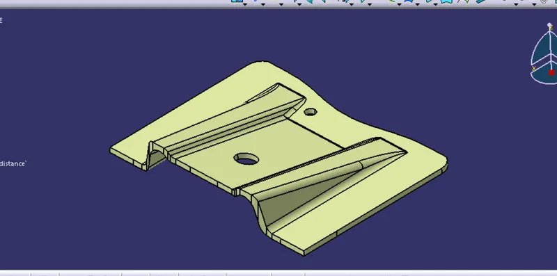
AFTER TRIM, IT BECOMES CLOSE SURFACE.
7. CLODED BODY : We need to make a closed body by making an insert new body and go to part design and then by close surafce option we will make closed body.
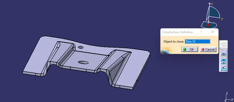
8. we wiil check the draft analysis of closed body.
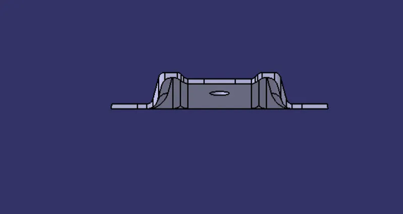
VIEWS
FRONT VIEW
SIDE VIEW
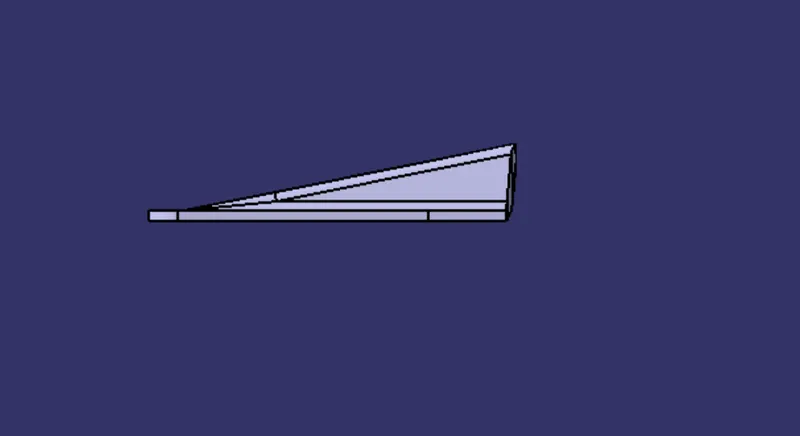
TOP VIEW
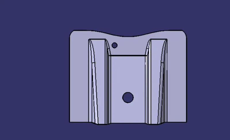
ISOMETRIC VIEW
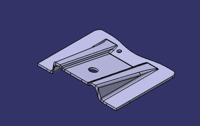
CONCLUSION : I have made the base bracket design by close surfce WITH proper draft direction.