Radar Mast & Final Assembly of Yacht
REPORT ON YACHT MODELLING :
OBJECTIVE:
To design all the parts of the yacht and assemble these parts together to make the yacht with the help of solidworks and then to give realistic view in nature .
INTRODUCTION:
To design the yacht, we use the SOLIDWORKS ( solidworks is a software of mechanical design which allows us to sketch quickly ina 3D ), to design all the parts and assembly . here we use surface and solid feature to modelled the parts adds on that we have given appearances to parts , then assembling of these parts by giving mates relation with proper constraints .
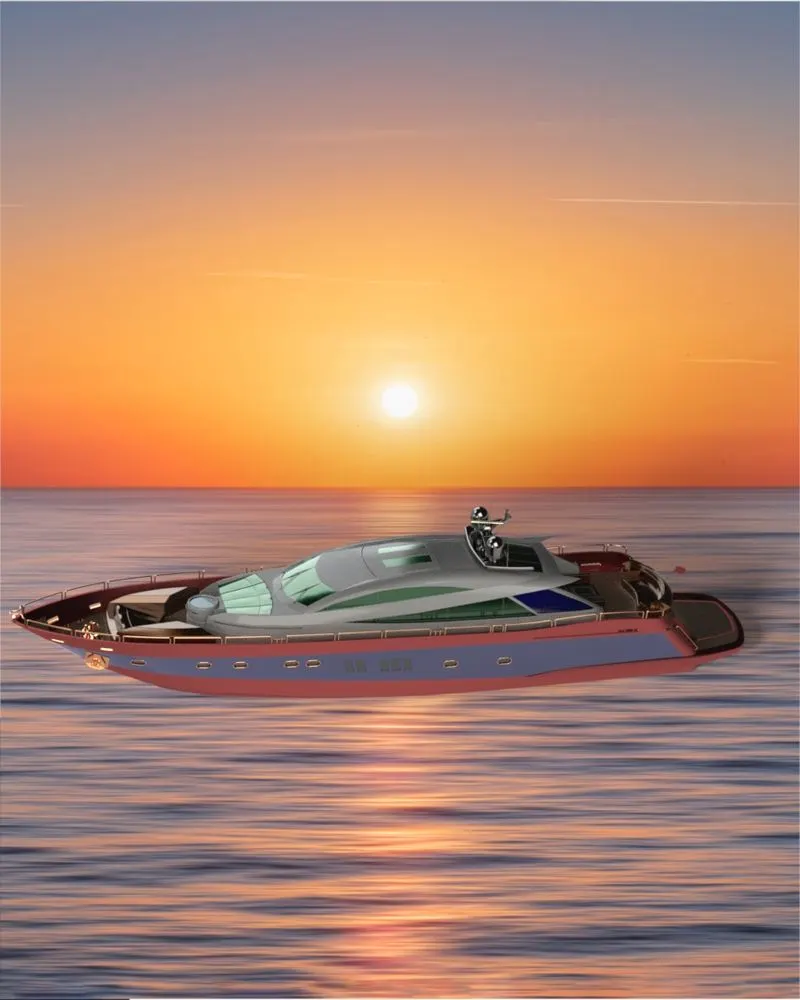
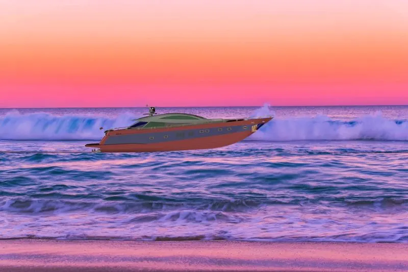
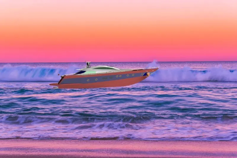
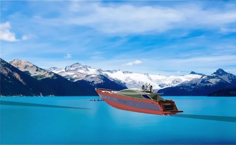
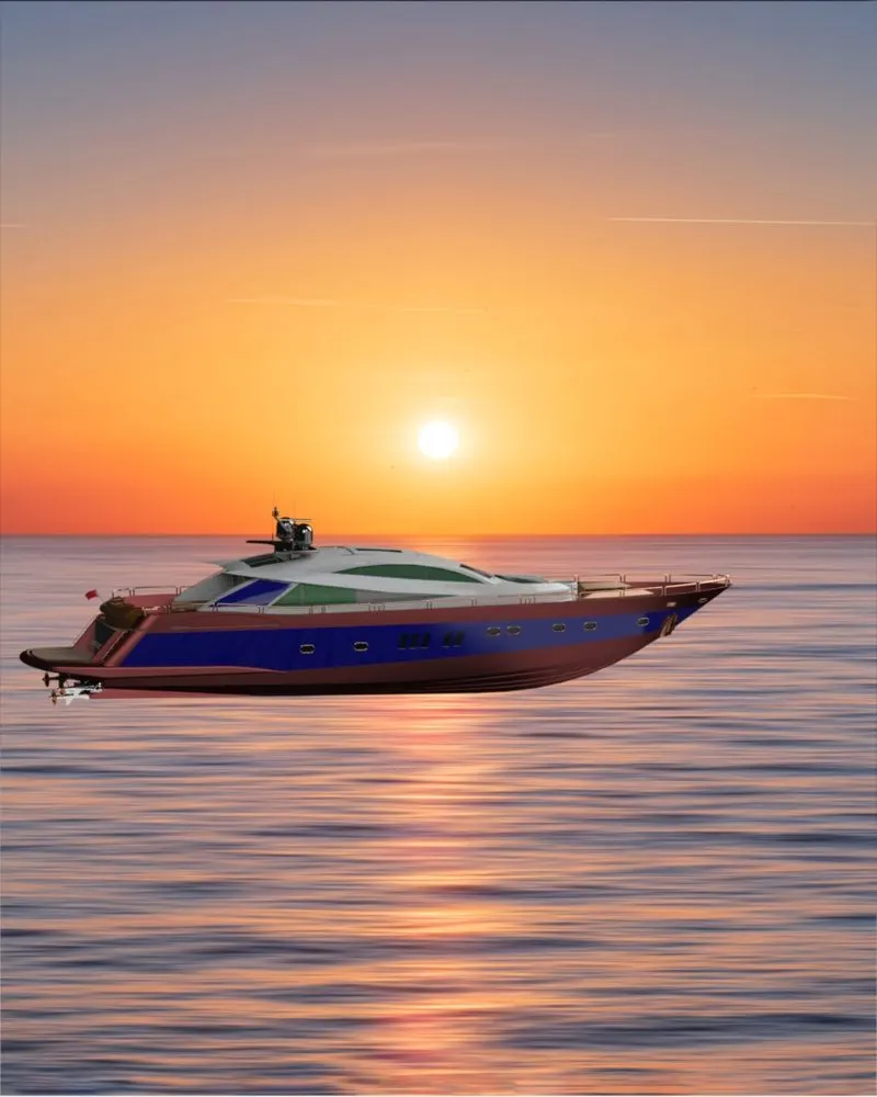
After assembling of these parts , we have given the realistic view in nature with the help of photoview 360 and solidworks visualisation.
DESIGN PROCESS:
Design process with the help of flow chart :
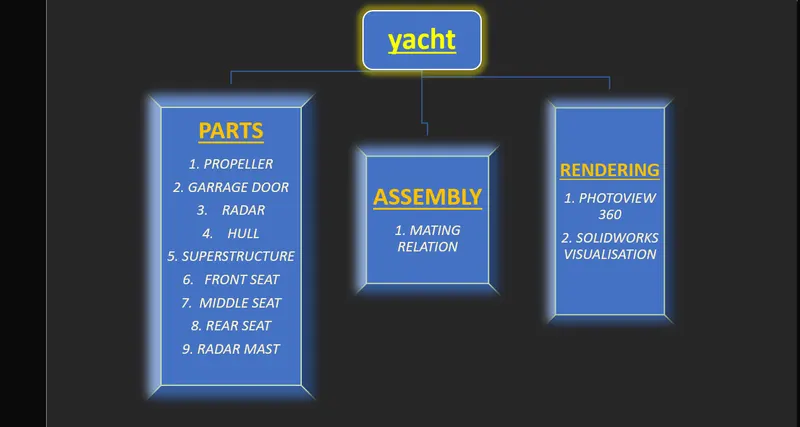
COMMANDS USED IN THE YACHT:
Sketch tools: To create the sketch in a 2D manner.
1. line : it is the basic sketch to draw any gemotery by drwaing line.
2. circle : to draw a circle.
3. Rectangle : to draw a rectangle
4. spline : it is used to draw a line with which we can give curve according to our object.
5. sketch fillet : in sketch only, to get round corner .
6. offset entities : to project a simillar geometry with an offset distance.
7. convert entities : to bring previous sketch into present one .
Feature tools ( Solid feature modelling )
1.extrude base : it is used to have add some thickness in the sketch.
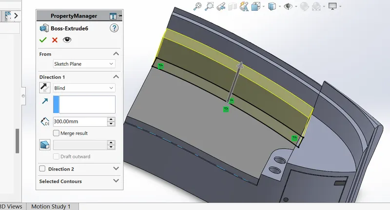
2.extrude cut : it is used to cut the solid part to reduce thickness in the geometry.
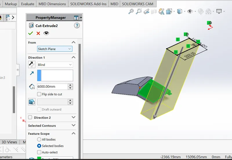
3.revolve base : it is used to produce revoute geometry around an axis.
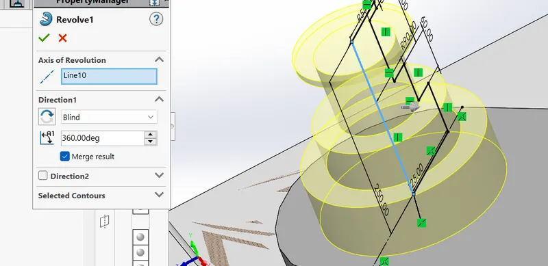
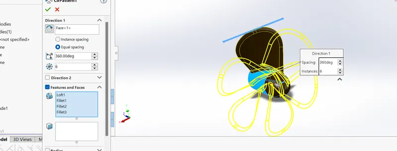
4. circular pattern : it used for pattern of same shape and size in a circular way.
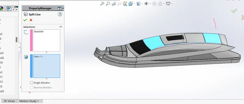
5. split line : it is used for split the faces into two parts.
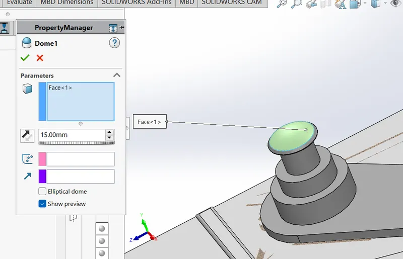
6.dome : it us used to give dome shaped structure to enhance our geometry.
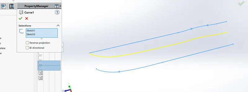
7. projected curve : it is a 3D curve, used to project curve with two different sketch which have same plane and perpendicular to each other.
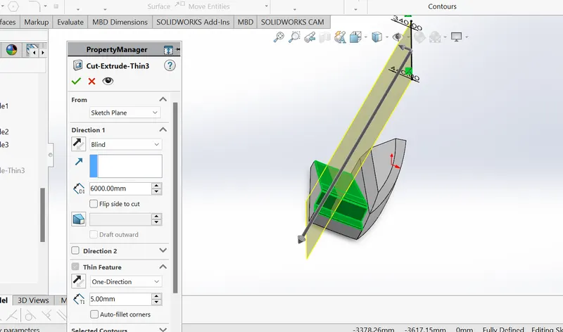
8. cut extrude thin : it is used for a cut the solid part which have enable thin feature which means to ahve very less thickness of solid part.
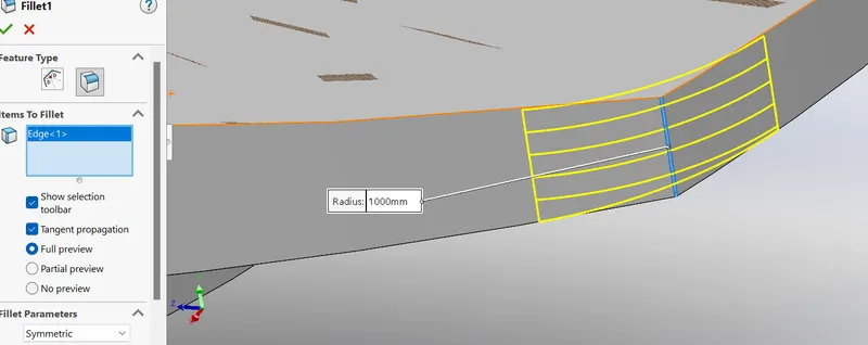
9. fillet : to produce a corner shaped object , by doing this , aim to have less concentration of geometry which leads to have better surface finish object.
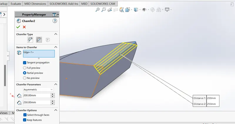
10. chamfer : it is used for having slope in the geiometry, by giving angle angle distance or distance distance relationship.
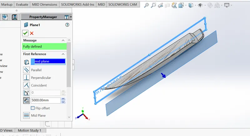
11. Refernce Plane : when we need to draw any sketch, which is not in the original plane we have , then we need to take reference plane , to draw our sketch .
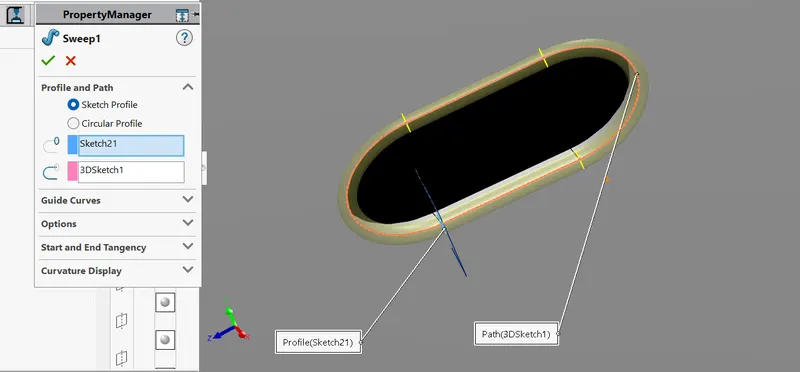
12. Sweep base : it is used to produce sweep pattern for an object.
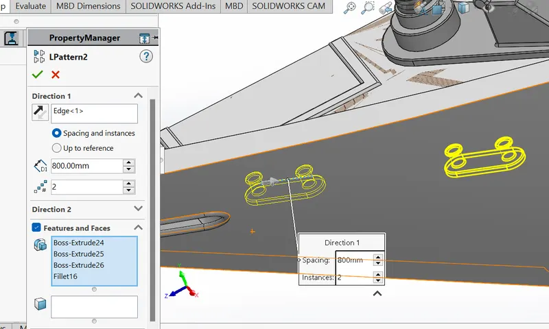
13. Linear Pattern : in this case , we pattern our objects in a linear way.
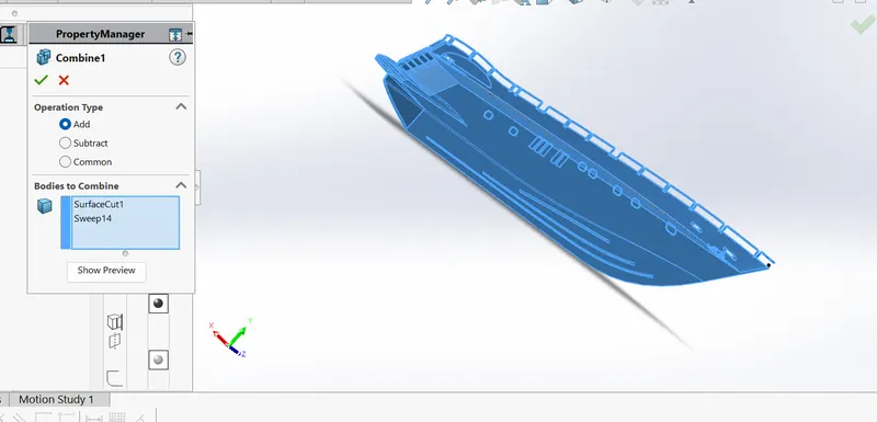
14. Combine : it is used for combine the solid body parts.
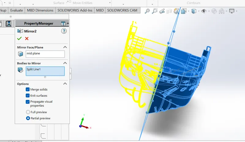
15. Mirror : mirror is something which have to replicate the same the same object , just opposite to the original object.
Feature tools of surface modelling : Surface modelling used for very thin thickness like surface objects only.
1. sketch pattern : it is used for pattern the sketch we have drawn.
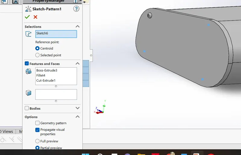
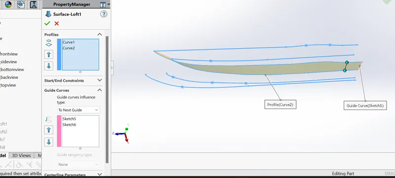
2. lofted surface : it is used for projecting the surface with the help two projecetd curves and guide curve, lofted basically means that, we draw exactly the same surface profile we want.
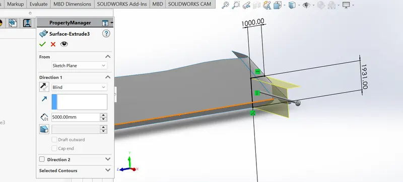
3. extruded surface : to add thickness in the sarface geometry.
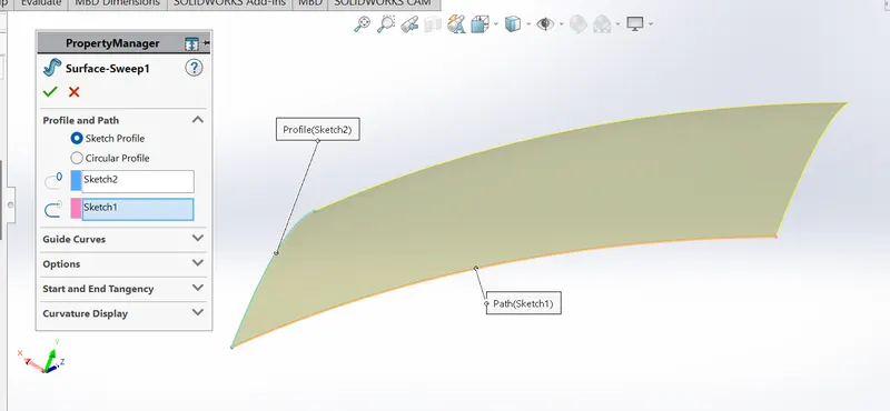
4. swept surface : to elongate our surface , that sweep is used.
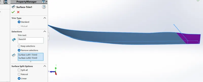
5. trim surface : it is used for trimming the surfaces.
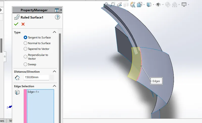
6. ruled surface : is is used for producung the same surface we want.
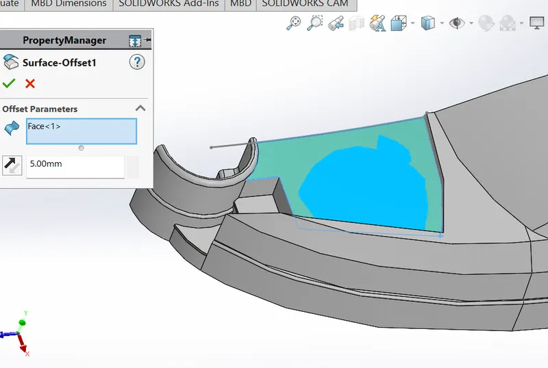
7. offset surface : it is used when we want some devaition from original sketch, we gave some distance.
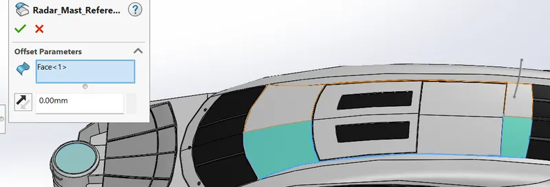
8 . copy surface : when we gave zero distance in surface offset , it is called copy surface , means we are copying that surface only.
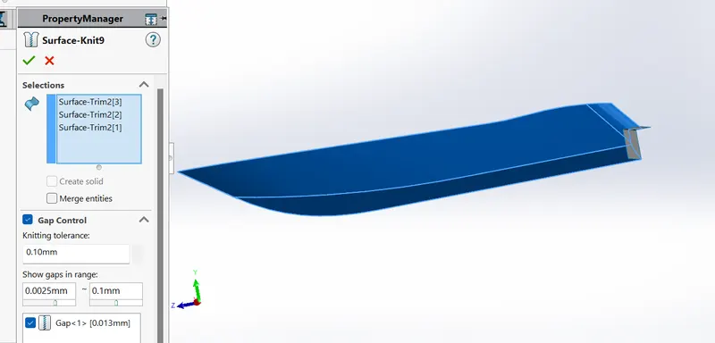
9. knit Surface : it is used for joining the two or more surfaces.
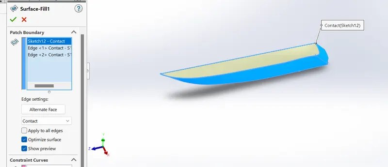
10. Surface Fill : is used for to fill between the two surfaces.
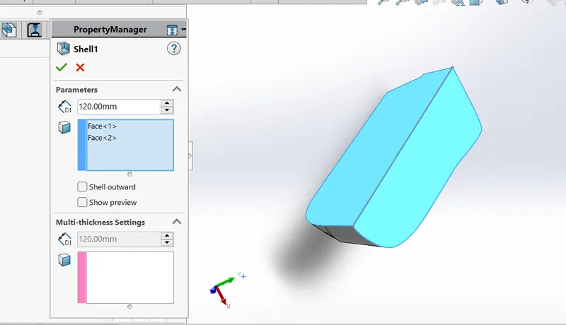
11. shell : it is use to create a hollow in the surface geometry.
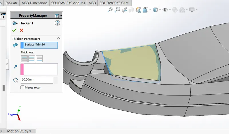
12. thicken : is is used for thicken the surface geometry.
MODELLING OF PARTS DESCRIPTION
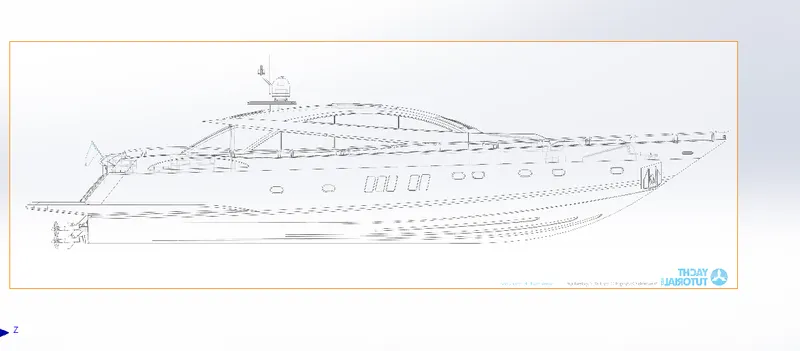
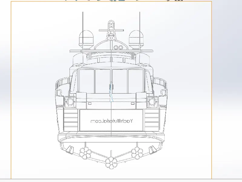
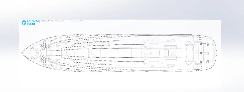
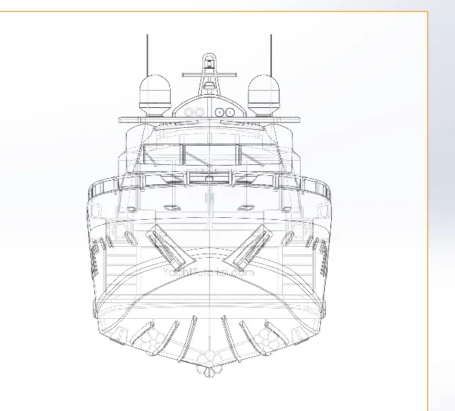
BLUEPRINT:
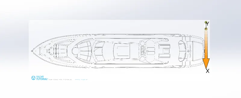
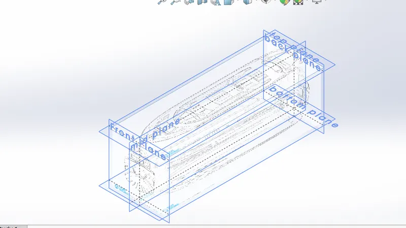
Blueprint basically the detailed section of the model , in which with light colour of the part has shown , with full dimension in scaler unit.
with the help of blueprint , we we can design our model in the best fitted manner and with a fully defined constraints.
Feature used in blueprint
Blueprint sideview
Blueprint backview
Blueprint bottomview
Blueprint frontview
Blueprint topview
2. HULL
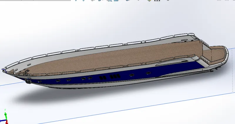
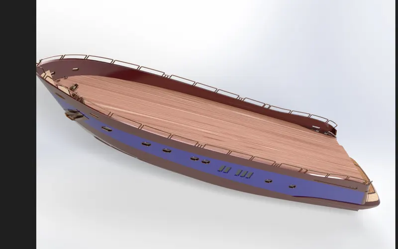
Hull is the body of yacht, in which every part is placed on it, hull is also the watertight enclosure means its shapes in such a way that protect the ship from flooding and structural damage.
in making the hull part, we have made some part which is attached in the hull part only , such as,
.Railing
.stairs
. anchor
. shaft for propeller
.windows
. deck surface
. hatch
. porthole
. stern
features used in HULL :
Blueprint setup
projected curve
surface loft
surface trim
surface extrude
surface knit
shell
boss extrude
cut extrude
fillet
chamfer
plane
sweep
helix
spiral
combine
split line
revolve
mirror
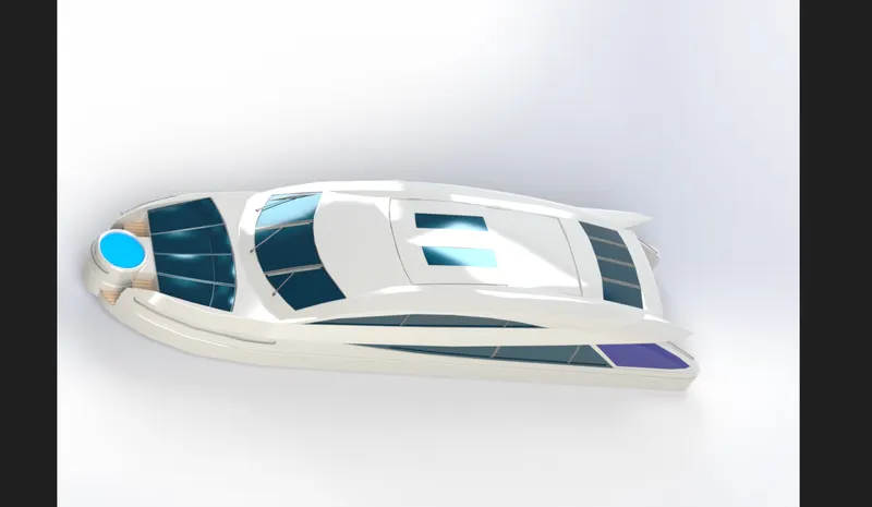
SUPERSTRUCTURE:
It is placed on the upper body of hull part that is main deck surface, it is basically a cabin part which is acontrol tower of aircrafts. it is joined by a process Explosive welding.
features used in superstructure :
surface extrude
plane
surface knit
fillet
chamfer
ruled surface
projected curve
surface loft
surface trim
knit surface
surface sweep
surface fill
3d sketch
surface extend
boss extrude
cut extrude
thicken
dome
split line
mirror
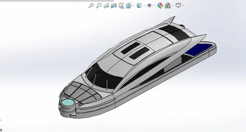
Render images of superstructure
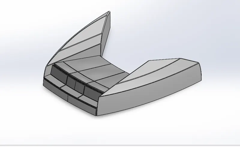
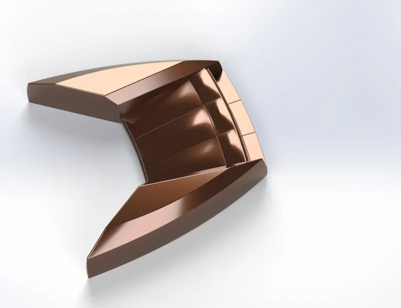
FRONT SEATS :
Front seats are placed on front of the superstructure, this seat has to made for having to realax and for luxurious purpose.
features used in front seats
suraface extrude
surface trim
suraface flll
surface loft
surface knit
surface sweep
chamfer
revolve base
mirror
dome
fillet
cut extrude
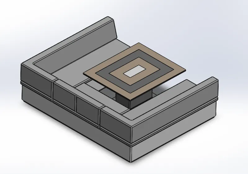
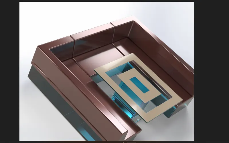
MIDDLE SEAT :
misddle seat is place back of the superstructure, this middle seat has table also for dine out. it can use for anything , which ever manner you like.
feature used in middle seat
boss extrude
refernce plane
chamfer
fillet
cut extrude
REAR SEAT :
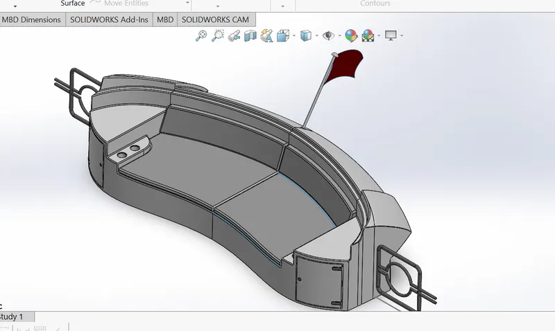
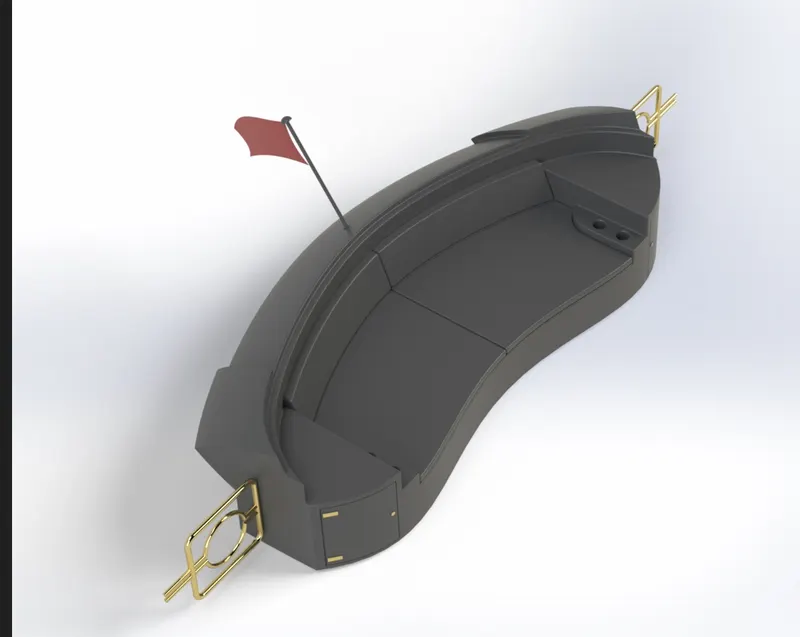
rear seat is place at the end of the deck surface, the rear seat is also have locker to put necessary things, it also consists of flag , to look good , it also provides some slots to put some utensils.
features used in rear seats
refernce plane
surface sweep
surface trim
surface knit
ruled surface
surface offset
surface extend
surface loft
boss extrude
cut extrude
fillet
chamfer
sweep
mirrror
PROPELLER :
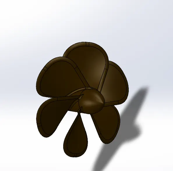
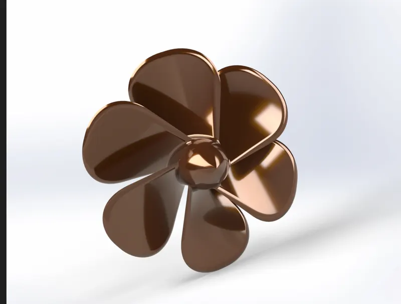
Propeller is the most important part of the ship, which is used for the movement for ship by producing thrust on water, propeller works on the principles of newtons third law , which says every action has an equal and opposite reaction and bernauli theorm , which says that sum of the potential energy , kinetic energy and pressure energy remains constant for an incompressible and non viscous flow.
features used in propeller
revolve
reference plane
loft
fillet
cut extrude
circular pattern
Garrage Door :
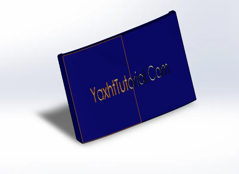
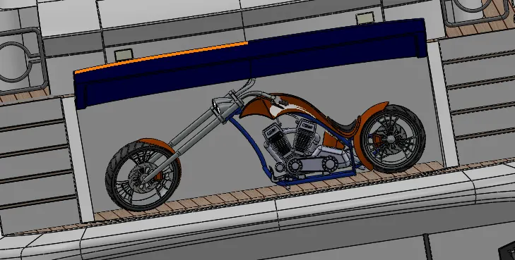
Garrage door is placed on the hull of deck surface , it is used for covering the garrage space which carrying the logistics part. This garrage door is open as it can move manually here.
Features used are
cut extrude
fillet
mirror
reference plane
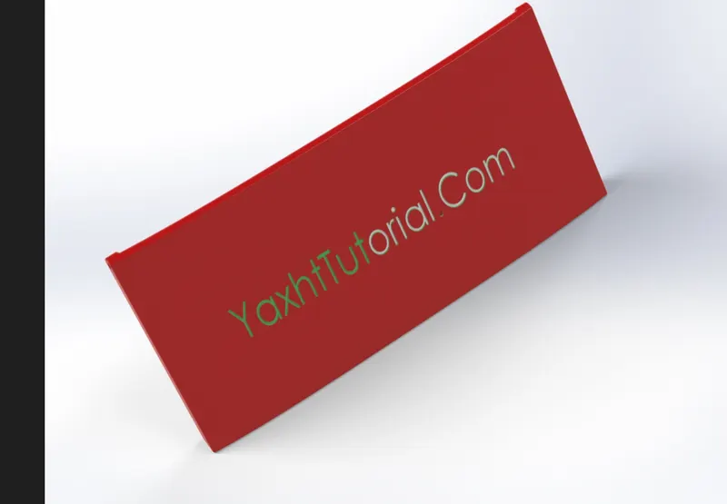
RADAR :
radar is used to detect the other ships and land obstacles, basically thet electronic navigation instruments that are used for rotating antenato sweep a narrow beam. radar uses radio waves for finding the position of moving objects.
features used are :
boss extrude
fillet
cut extrude
mirror
sketch pattern
split line
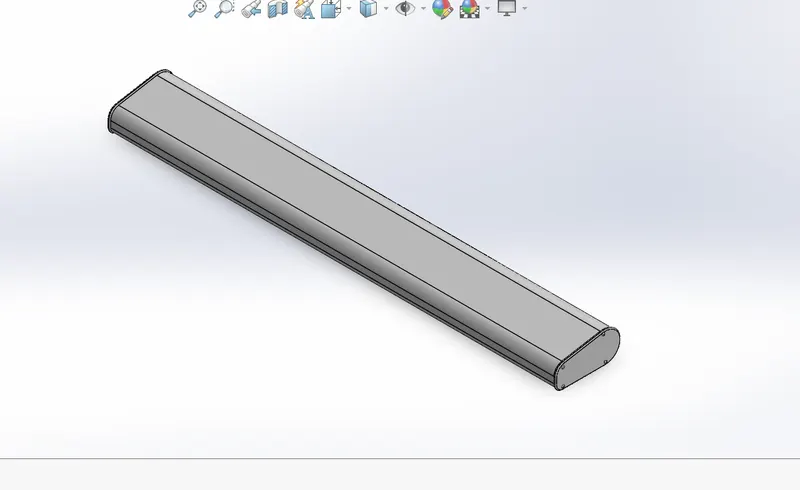
render images of radar
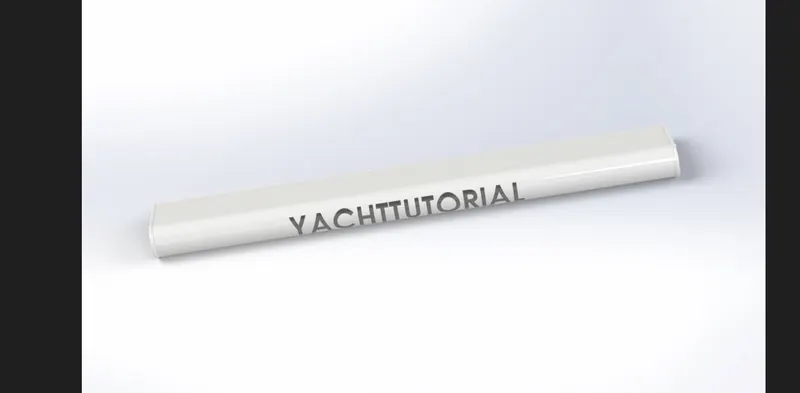
Radar Mast :
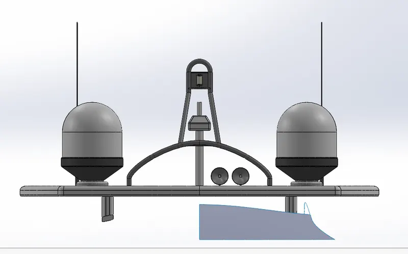
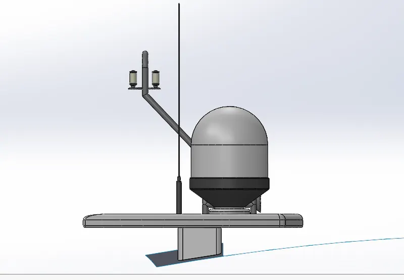
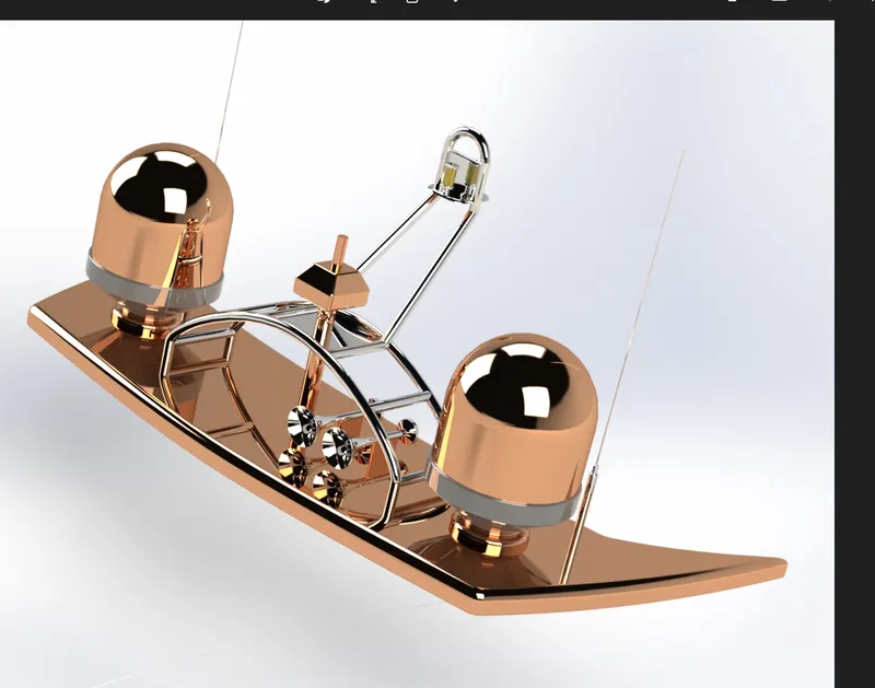
radar mast is mounted on the top of the superstructure, its basic purpose to navigate the lights, carries radar and ship horn .They are made of high tensile steel.
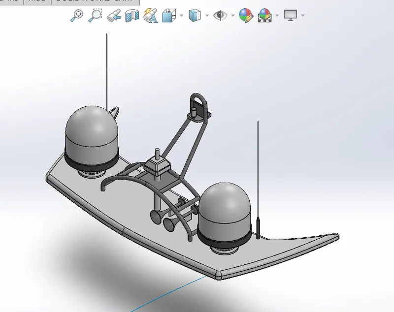
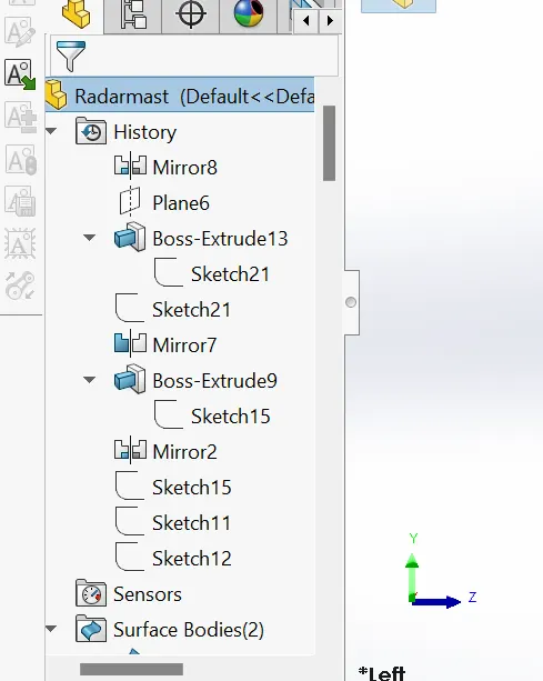
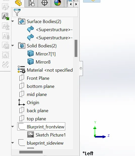
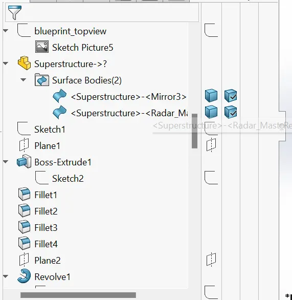
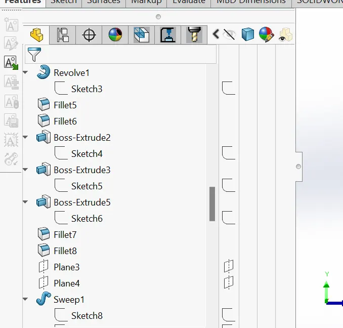
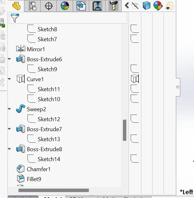
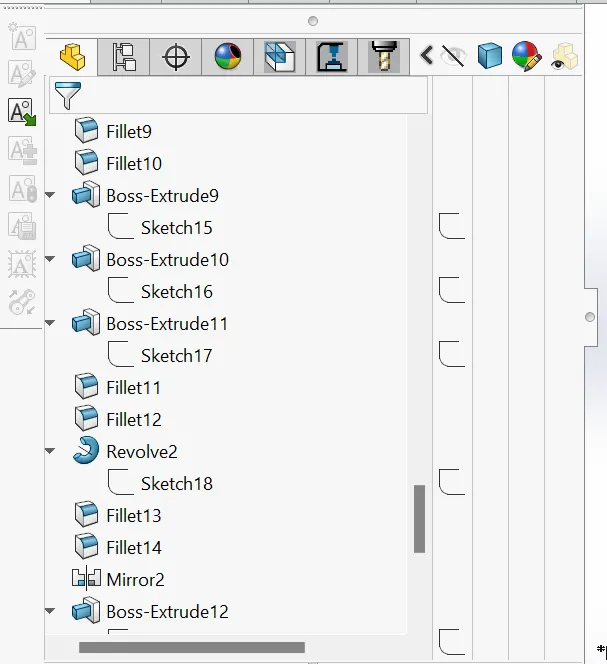
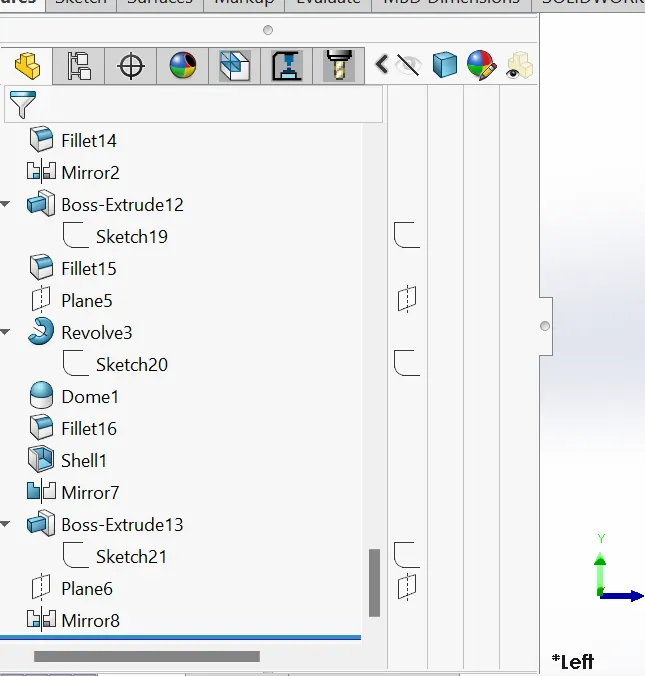
Feature tree of radar mast
YACTH ASSEMBLY :
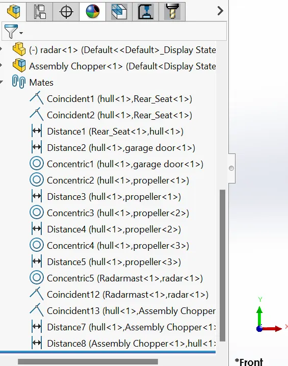
Assembly is done with combining all the parts together in the assembly section of solidworks software. For assembly the parts , i have given some realtion between so that they attached to each other and looks to single yacht. we have done assembly by inserting parts of yacht one by one into the assembly section of our yacht model.
The MATE relation which is used here in the assembly of yacht are :
COINCIDENT RELATION : this is used for bringing both the paarts to one point.
CONCENTRIC REALTION : this is used for the propeller one which is be concentric with the shaft part.
DISTANCE RELATION : this is used to have some distance between the parts like placing of rear seat , i have given the distance , like at what distance it should be palced from the hull rear point.
ALSO i have placed the american chopper in the garrage area.
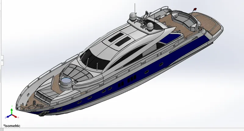
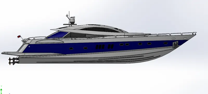
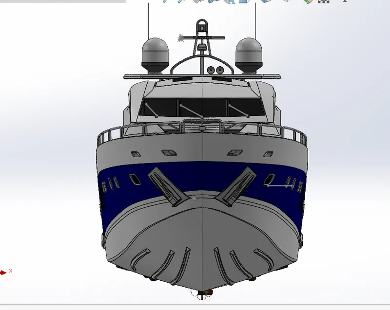
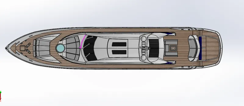
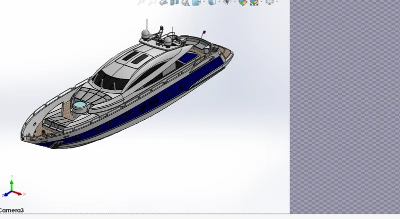
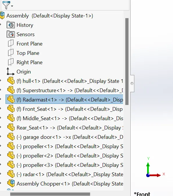
feature tree of yatch assembly
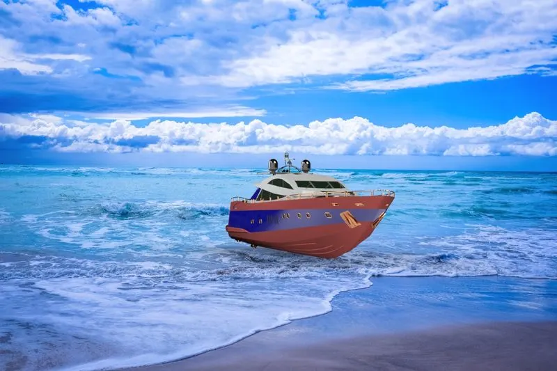
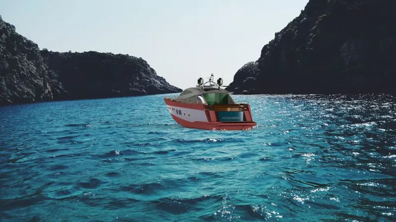
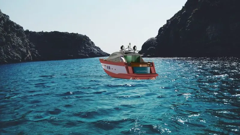
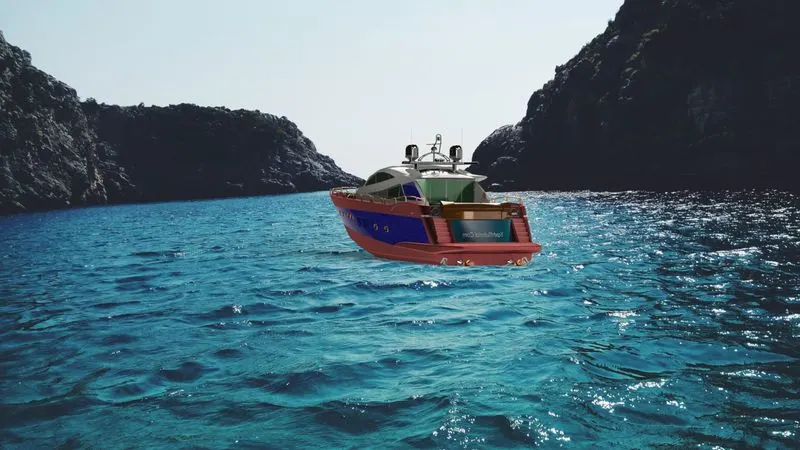
SO , far , we have done all the works of yacht , from modeeling of parts to assemble of parts to make the yacht , we have made the yacht, now to work on the atractive looks , view to real worls in nature, and more and more attractive.
so for this i have done the appearances in the yatch to give color to this yacht , putting decals and some renderings.
APPEARANCES: To have a attractive yacht, i hav given appearnces to this yacht.
DECALS : Decals is used for to view objects cool or looks attractive .In this yacht , given decals to stairs , garrage doors , hull upper part.
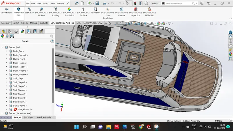
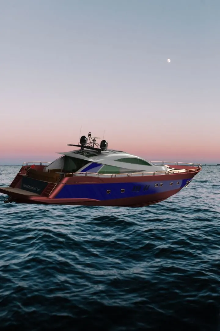
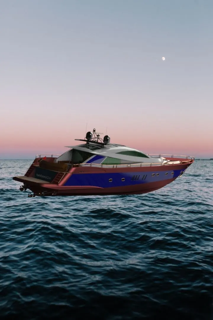
RENDERING : Rendering is used to give view thats looks realistic in nature , it means whenever we objects made , it should looks simillar to real world, in this case we have done Rendering by SOLIDWORKS VISULAISATION AND PHOTOVIEW 360.
SOLIDWORKS VISUALISATION :
It is the parts of soliworks only.
It helps to create in a real world view
It has the feature to create our own background backlates to the enviroment
PHOTOVIEW 360 :
It is also used for creating the enviroment background in scenic view section
It has the features to put decals to our models
It also has the lighting effects to our models.

CONCLUSION:
Thus my yacht model is completed with help of above mentioned tools. and i hope you like it.
HERE I have given the link of all the parts and assembly of yacht.
https://drive.google.com/drive/folders/1vpUpxt4-zSbO0S2lsltWw6TTg9UhqRRY?usp=sharing