Photo Realistic Rendering
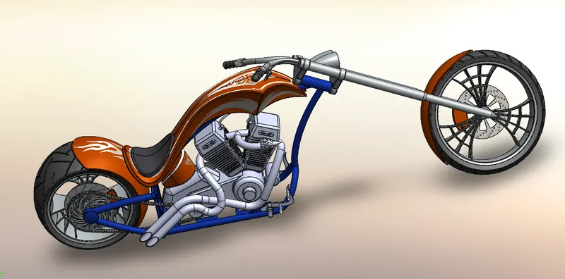
MODELLING OF AMERICAN CHOPPER
OBJECTIVE
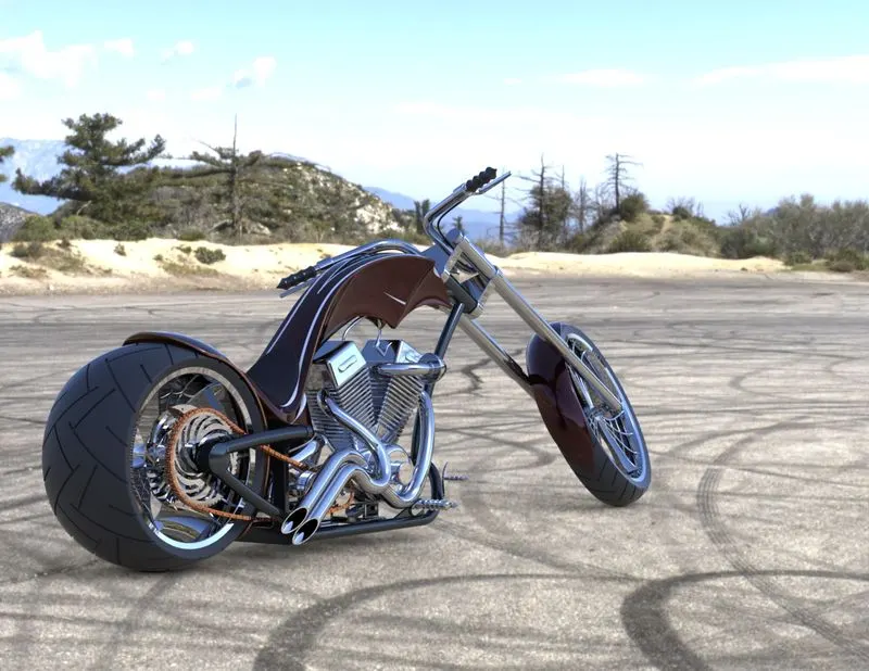
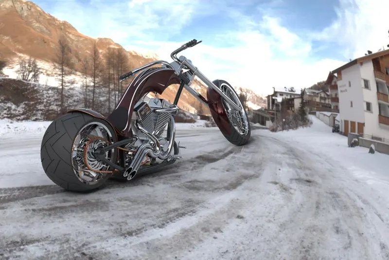
we are modelling this AMERICAN CHOPPER with the help of SOLIDWORKS software and here we have learned solidworks features and tools and also photoview360and solidworks visualisation to give relistic decals and rendering.
INTRODUCTION
Solidworks is the easiest ways for beginers for learning 3D modelling. soliworks is useful tools in automobile sector, we have preapered our american chopper here with making parts first , then we have assembled these parts into one then we have put decals to give attractive look and also using solidworks visualisation we have provided rendering to give more realistic in nature or environment or to give look to real world.
DESINGN APPROACH USING FLOW CHARTS
For any modelling the best way to represnt using flow charts, because flow charts gives graphical representation and summary of our model.
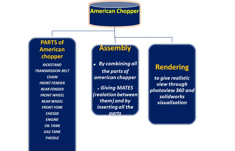
Descrption of all the sketch and features tools we used here are-
SKETCH TOOLS : It is 2D sketch which is a combination of all the basic tools which we use for instances line , circle , rectangle etc.
some of the basic sketch tools are-
Standard dimension : Here we have taken our basic satndard dimensions is in (mm).
PLANE : It is a 2D sketch,in which we take reference from where we need to do sktch, basically we have 3 plane here which are bottom plane , top plane , Right plane.
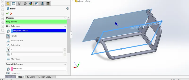
SMART DIMENSION: It is that Dimension which gives automatically dimensions to put.
LINE : to draw the lines.
CIRCLE: To draw the circles.
ARC : to draw the arc , here we mostly use 3 point arc.
SPLINE : it is used for a continus curves and smooth curves .
RECTANGLE: it is used to draw a Rectangle.
CONVERT ENTITIES : like if there is hidden sketch behind our new sketch and we want to bring into our areas of work , so that we can use that entities or that bold line convert entities, for that we used convert entities.
INTERSECTION CURVE : similar to convert entities, for bringing curve part we use intersection curve.
CURVE : It used to Draw a curve, it has 2 parts which we used here are-
PROJECTION curve : In this two differnt curve at different plane take to combine these to one to get a 3D curve
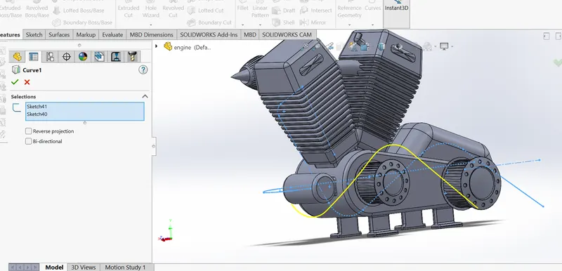
COMPOSITE curve: in this we combined all the curves.
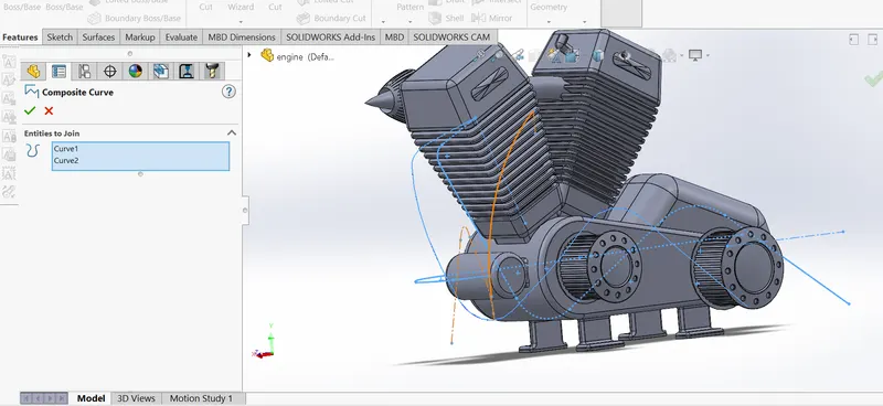
TRIM: Trim is used for removing the extra lines from our sketch and remember that before doung trim , we need to convert entities first.
FEATURES DESCRIPTION : Features means after drawing the sketch , with the help of all the sketch tools, we exit the sketch and ready for giving into a 3D model.
Someof the features tools are-
EXTRUDED BASE/BOSS: In this it adds thickness to 2D sketch .
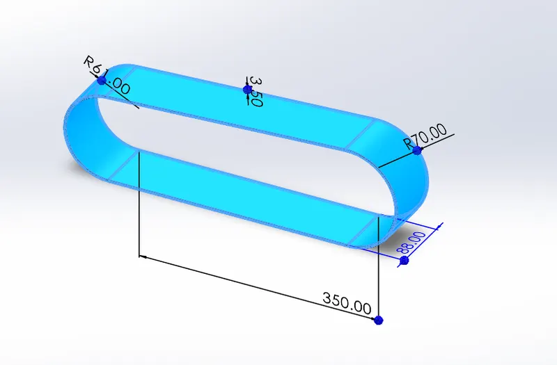
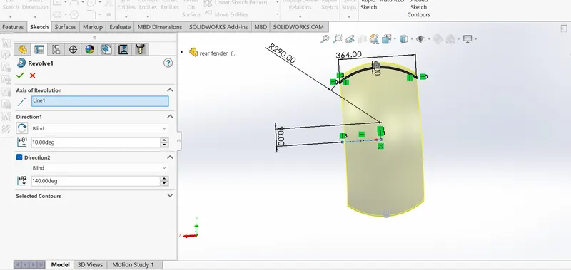
REVOLVED BASE/BOSS: It is used to create solid 3D model around an axis.
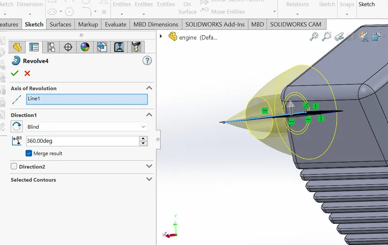
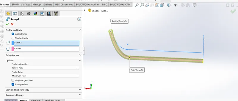
SWEPT BASE/BOSS: It is used to create a solid by moving a profile along a path and profile should be closed.
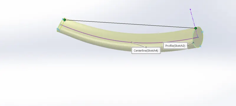
LOFTED BASE/BOSS: It is a important feature tools especialy when we working with surface modelling, as it creates a shape by making transition between multiple profiles and guides curves. It allows to set tangency for the first and last profiles.
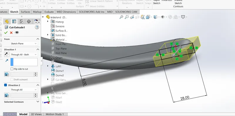
EXTRRUDED CUT: it is used for cut the some thickness part which we added in 2d sketch .
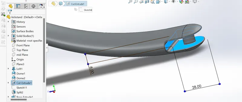
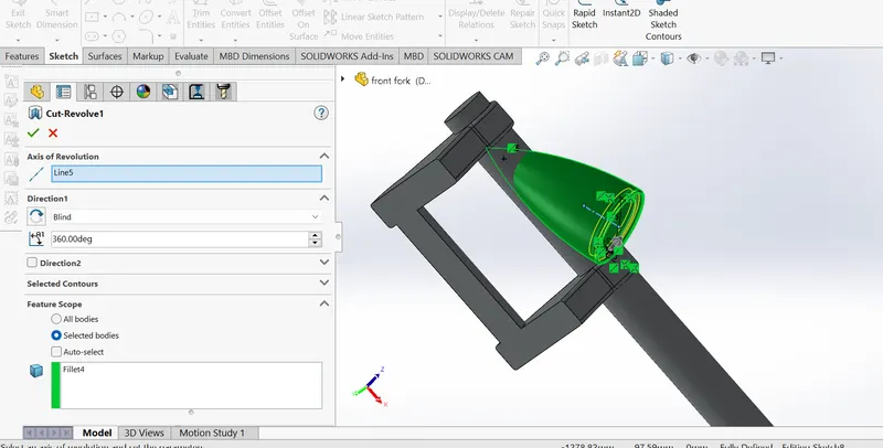
REVOLVE CUT: It used to cut a profile around an axis creating complex geometry in a single feature.
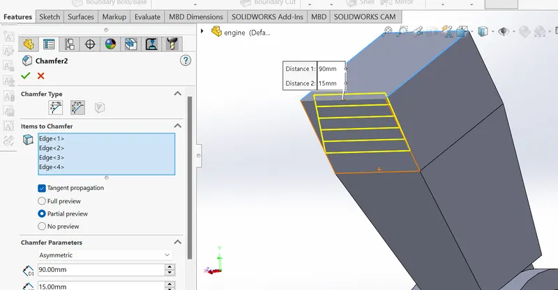
CHAMFERS :Chamfers are the sloped edged of a part.
FILLETS: fillets are used for rounded the corners of a parts.
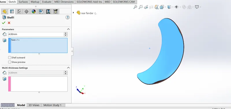
SHELL : it is used for hollow a part
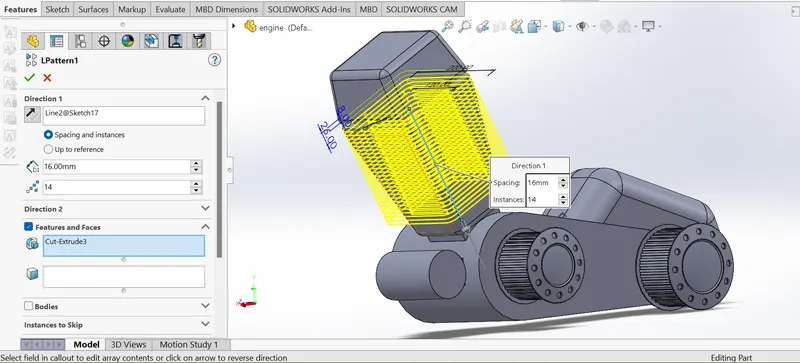
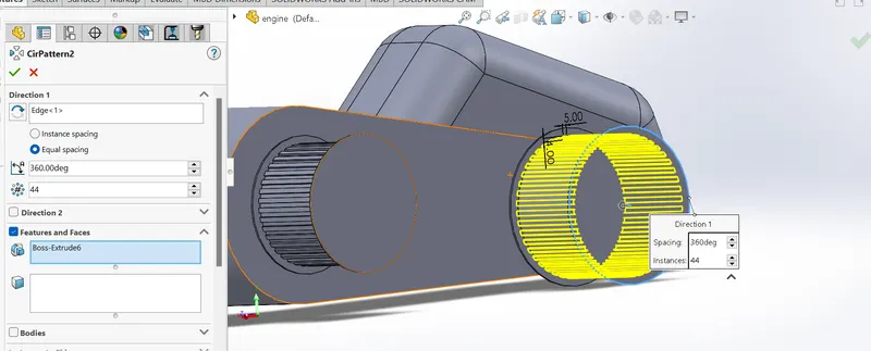
PATTERN: patterns is used for having simillarwork to original work, here we have have used linear pattern and circular pattern.
LINEAR PATTERN:
CIRCULAR PATTERN:
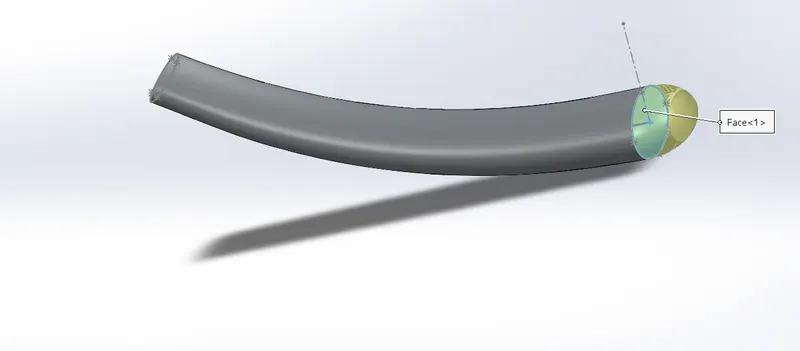
DOME : It is used to create a dome shaped.
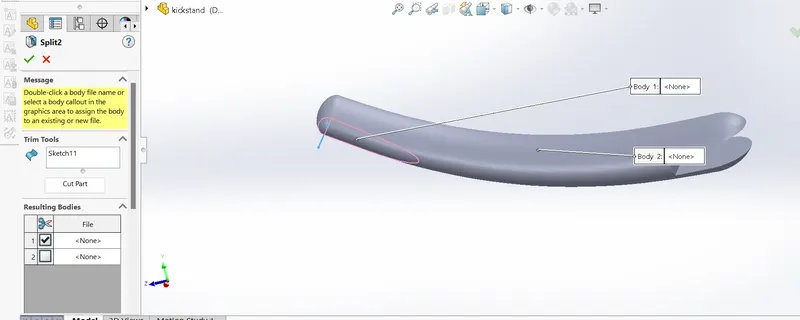
SPLIT: to remove some materials .
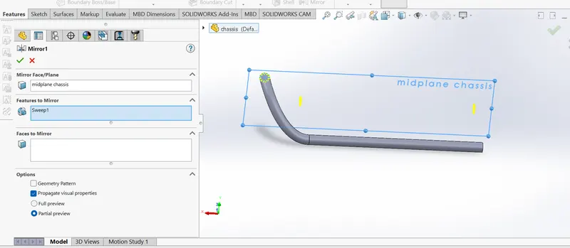
MIRROR: it will mirror exactly to originals ones.
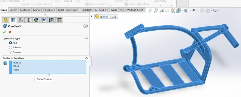
COMBINE : in this after mirror we combine all the mirror , fillet parts to look as a one single feature.
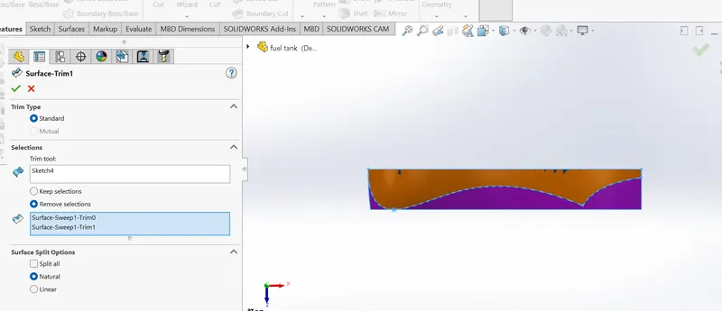
SURFACE TRIM: to remove the surface.
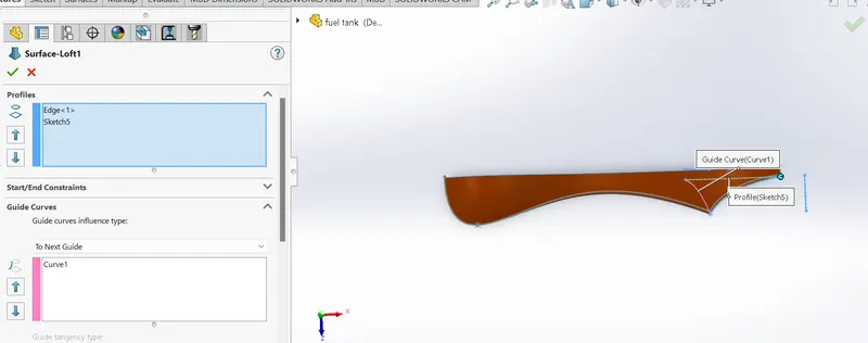
SURFACE LOFT: surface generated by multiple 3D curve, which creates a smooth tangency between the selected curves.
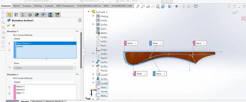
BOUNDARY SURFACE: It creates a surface can be continous curve in all sides of surface.
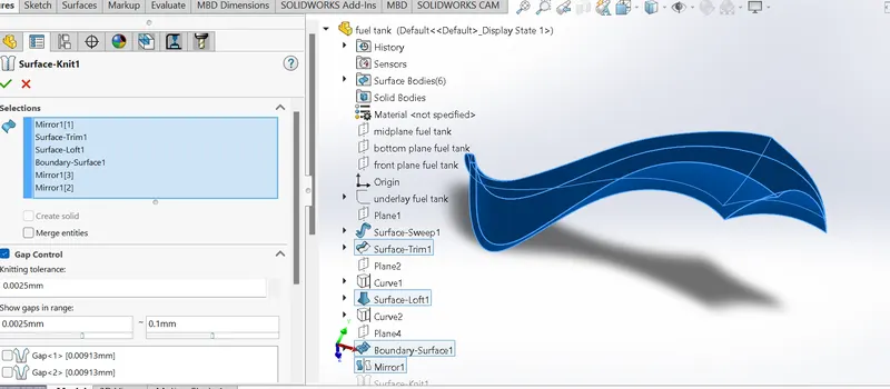
SURFACE KNIT: It is that tool which is used to combine two or more faces and surfaces into ONE.
PARTS OF AMERICAN CHOPPER
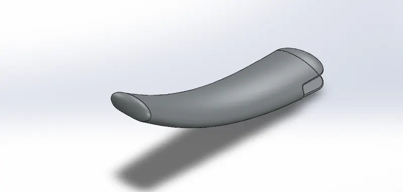
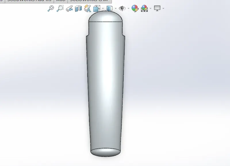
1. KICSTAND : It is used for to hold bike upright postion ,wihout having to lean it against something.
features used :
. 2D Sketch
. loft
. dome
. cut extrude
. boss extrude
. split
. fillet
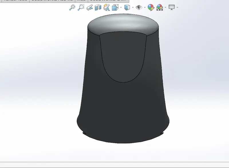
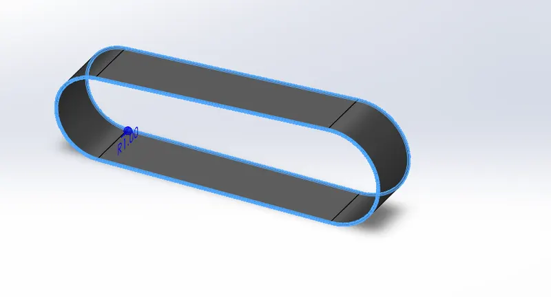
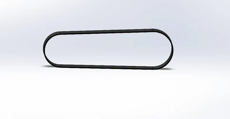
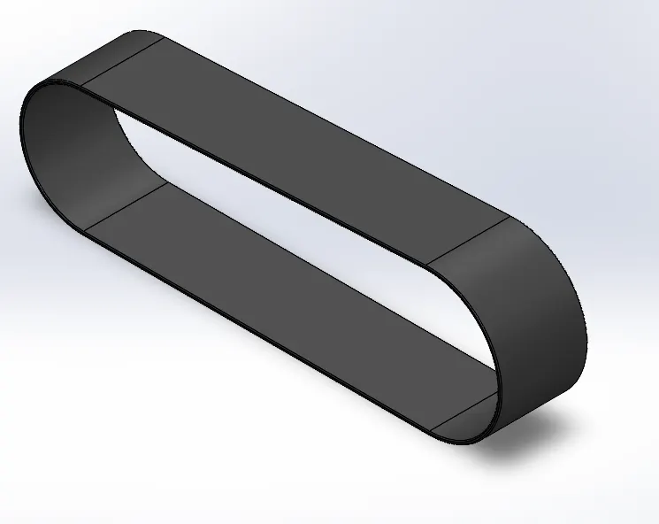
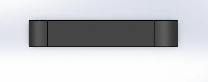
TRANSMISSION BELT: It used for transmitting power with help of pulleys, this transmission belt has two sides one is tight side and one is slack side.
FEATURES USED:
. 2D sketch
. boss extrude
. fillet.
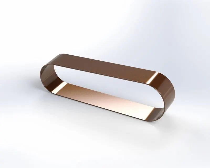
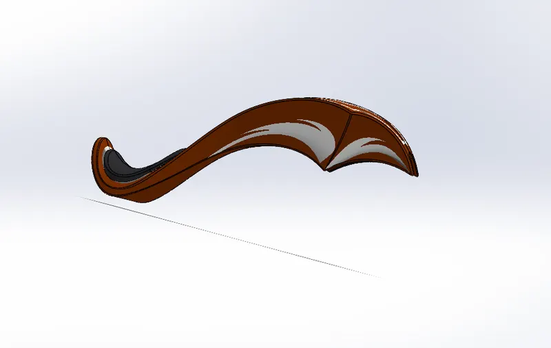
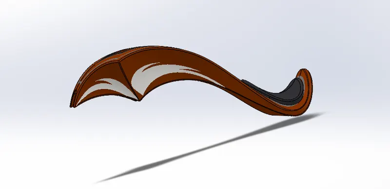
3. REAR FENDER: It is mounted on rear wheel of automobiles, its main purpose to prevent from mud, sand and other road spray.
Rear fender also gives looks to tyre .
FEATURES USED:
. 2D sketch
. revolve
. split
. fillet
. shell

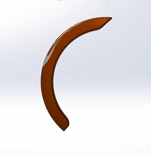
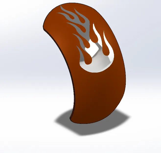
4. FRONT FENDER: Similar purpose to rear fender, it is mounted on front wheel drive.
FEATURES USED:
. 2D sketch
. revolve
.split
. fillet
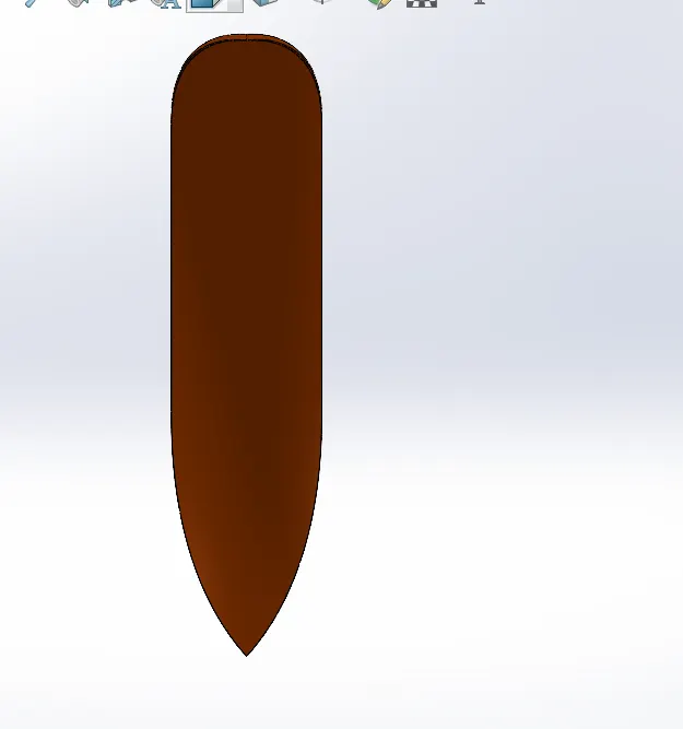
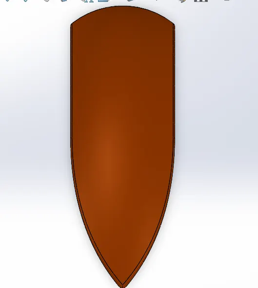
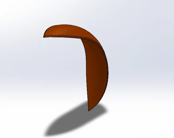
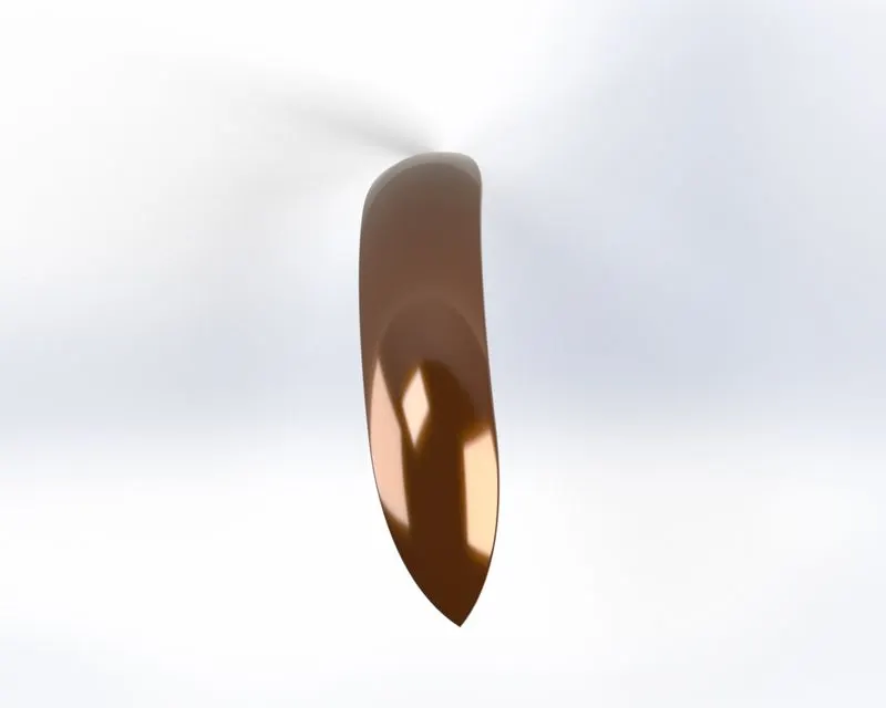
5. PADDLE: It refers to any flat paddle without cage , materals which is used for paddle are aluminum and nylon.
FEATURES USED:
.2D sketch
. boss extrude
. fillet
. revolve
. dome
. chamfer
. linear pattern.
.
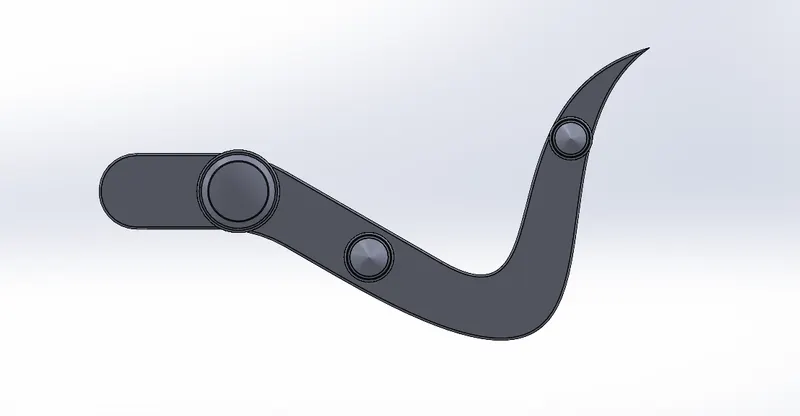
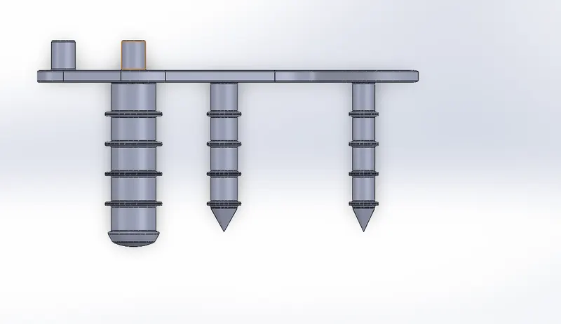
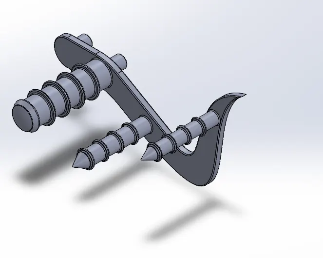
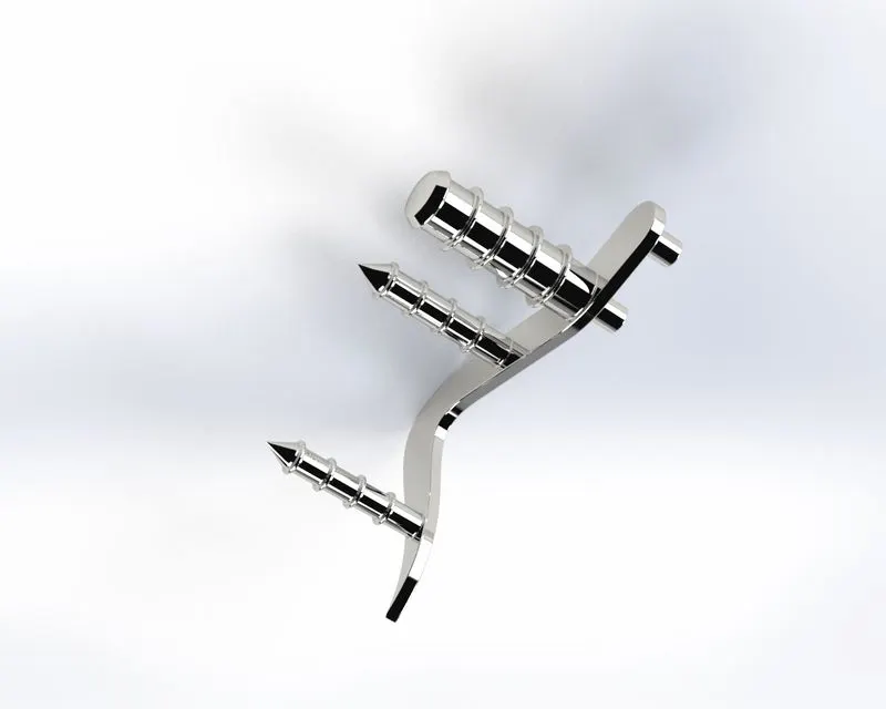
6. REAR WHEEL: It is the back of automobile, rear wheel drive pushes the vehicle forward . rear wheel drive is a form of engine and transmission layout used in motor vehicles. It supports the chassis , also spports the fuel tank.
FEATURES USED:
.2D sketch
. revolve
. boss extrude
. cut extrude
.circular pattern
. combine
. cut revolve
. fillet
. chamfer
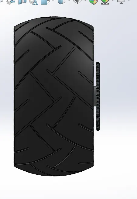
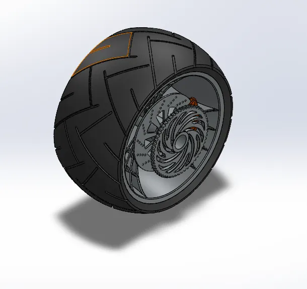
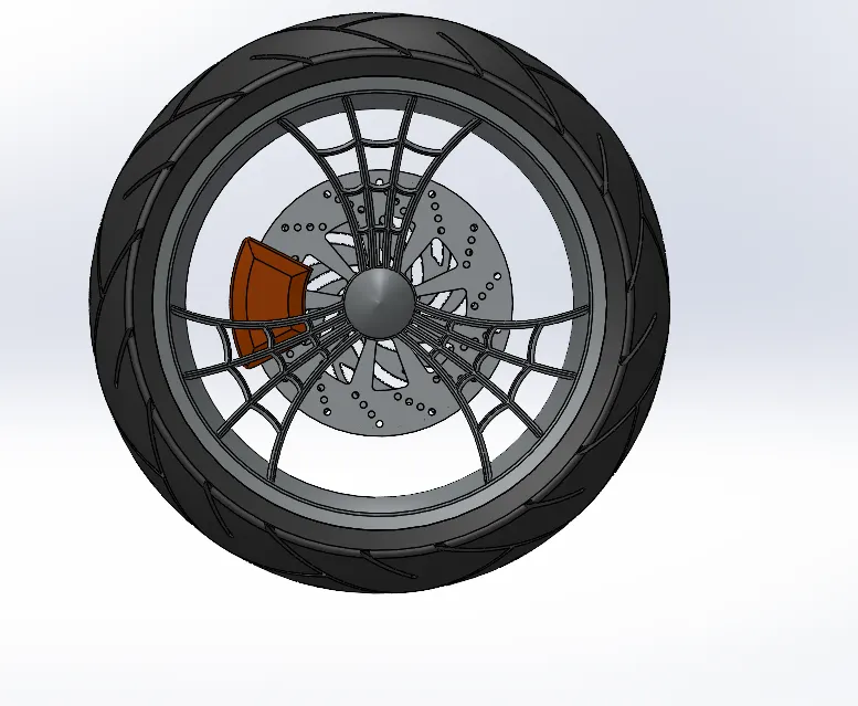
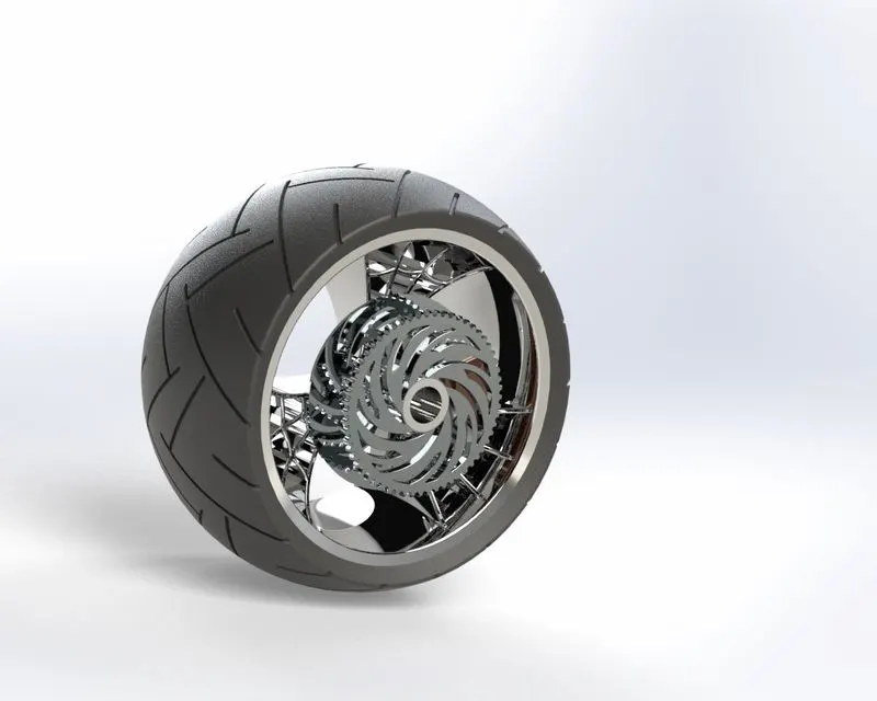
7. FRONT WHEEL: In this power from the engineis delivered to the front wheels. the front front wheel are pulling. It is attached with the front fork.
FEATURES USED:
. 2Dsketch
. revolve
. boss extrude
. cut extrude
.circular pattern
. fillet
. chamfer
. combine
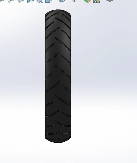
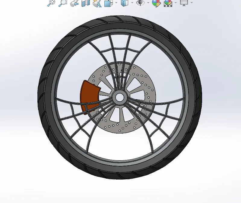
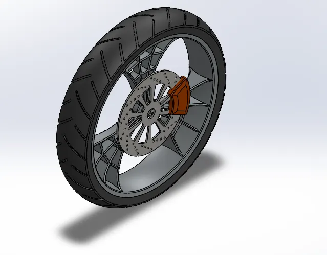
8. OIL TANK: This is basically a lubricating tank, the basic purpose of oil tank is to make sure that enough lubrication is provided to all the engine parts so that friction and wear reduced.
FEATURES USED:
.2D sketch
. boss extrude
. combine
. fillet
. shell
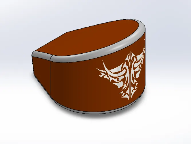
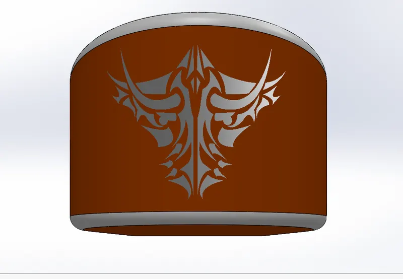
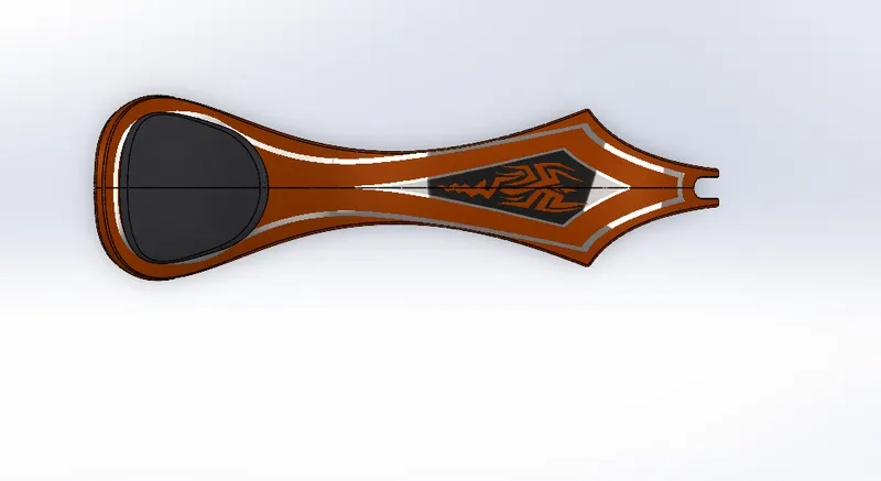
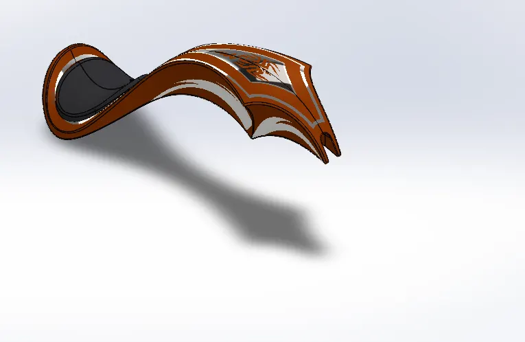
9. GAS TANK: it used for storing the gas, and also it provides contact between the rider and the bike beacuse seat is placed above the gas tank only.
FEATURES USED:
.2D sketch
. plane
. surface sweep
. surface trim
.curve
. surface loft
.boundary surface
. mirror
. surface knit
. split
. surface extrude
. fillet
. cut sweep
. shell
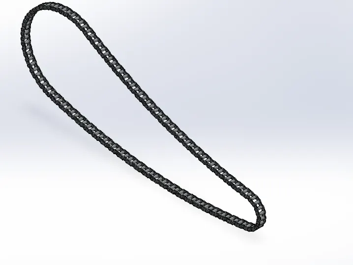
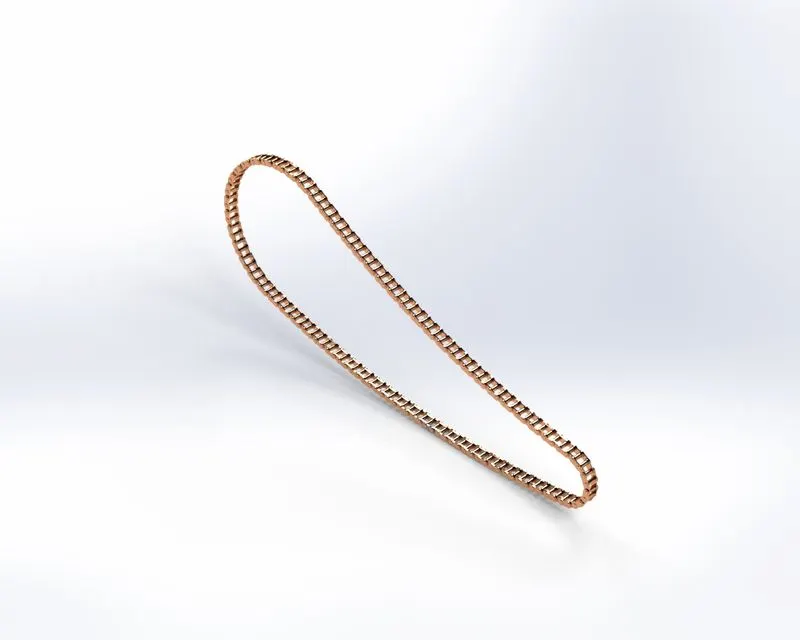
10. CHAIN :It basically transfer the power from the pedals to the wheel drive of a vehicle. materail used for this chain is usually made from plain carbon or alloy steel., but some are made from nikel so to prevent from rust.
FEATURES USED:
.2D SKETCH
. BOSS EXTRUDE
. FILLET
. CIRCULAR PATTERN
.MIRROR
11. FRONT FORK: It allows the front wheel to rotate about the steering axis so that the bike will be in a balance condition also the the word fork means suspension of a bike. It is attached to rear wheel.
FEATURES USED:
. 2D sketch
. revolve
. boss extrude
. fillet
.linear pattern
. cut extrude
.domw
. curve
. sweep
. pane
. mirror
. combine
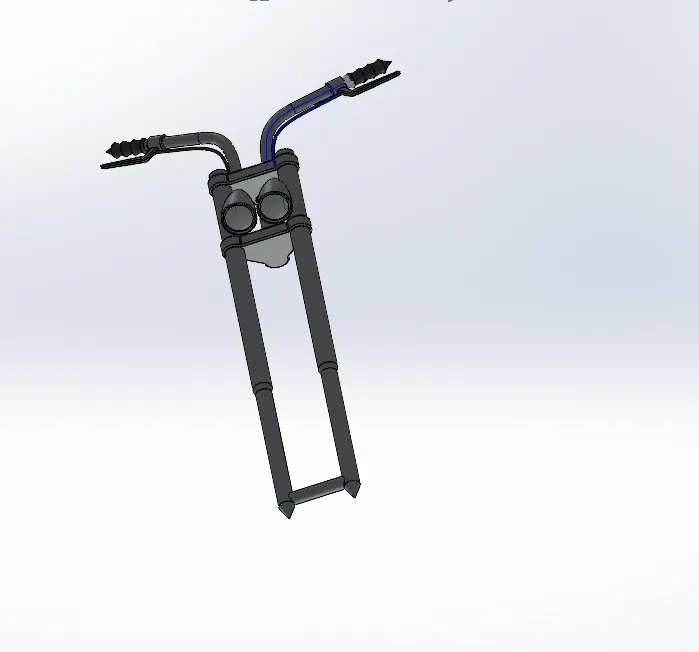
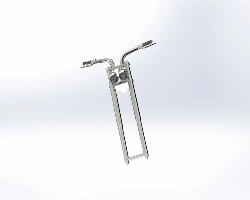
12. ENGINE : it is an engine which is used to give a power to motor cycle . Motorcycle engines basically have 2 strokes or 4 strokes IC engine, inside internal combustion engine, there is a fixed cylinder in which there is a piston which moves from top dead centre to bottom dead centre and in these moving down and up, compression and expansion take place respectively, through this process , engines gives power to motorcycle.
FEATURES USED:
. 2D sketch
. blueprint engine
. boss extrude
. fillet
. revolve
. plane
. circular pattern
. dome
. cut extrude
. chamfer
. linear pattern
. split
. mirror
. sweep
. combine
. curve
. composite curve
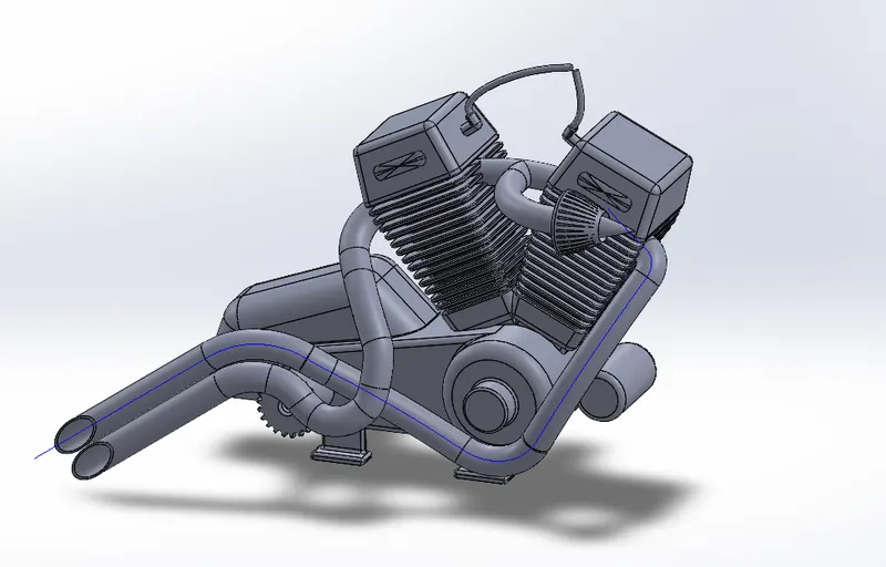
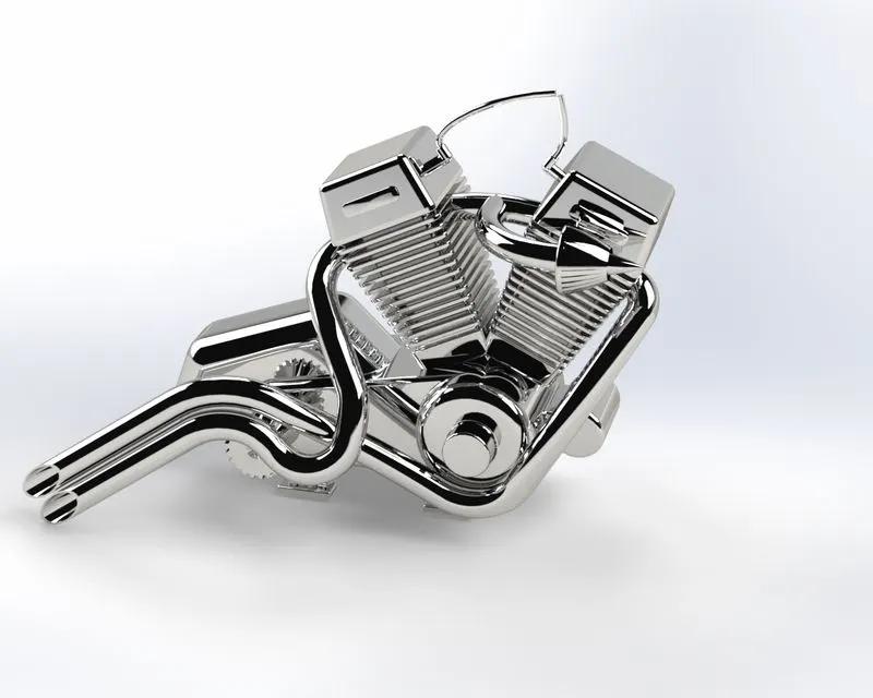
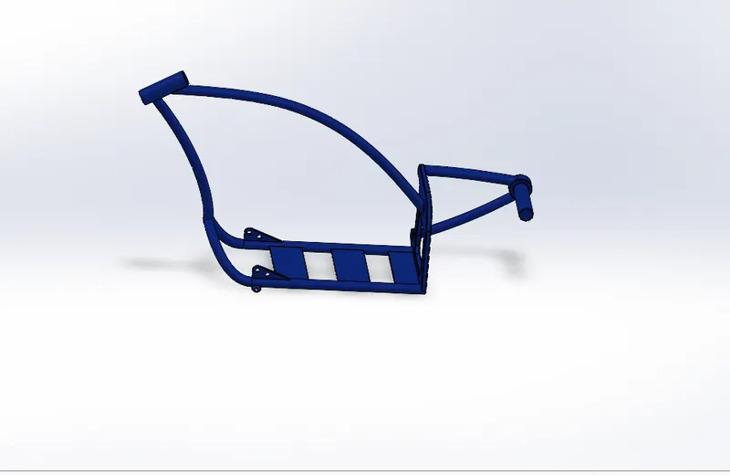
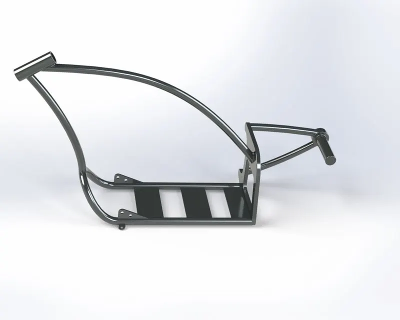
13. CHASSIS: It is a backbone of the bike as everything is placed on chassis, it refers to frame of a bike as it is the foundation structureof any automobile that supports it from undercarriage.
FEATURES USED:
. blueprint chopper
. 2D sketch
. curve
. sweep
. mirror
. boss extrude
. cut extrude
. chamfer
. fillet
. plane
. dome
. split
. combine
. revolve
14. ASSEMBLY : In this we combined all the parts into one, by first inseting the parts one by one and giving mates between them ( mates is basically a relation between them like coincidence, tangent, parallel) . Mates should be like that rear wheel , front wheel and paddle should tangent to the ground, so to give realistic model.
FEATURES USED:
. mate
. mirror pedal
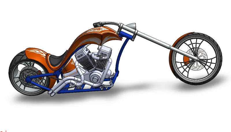
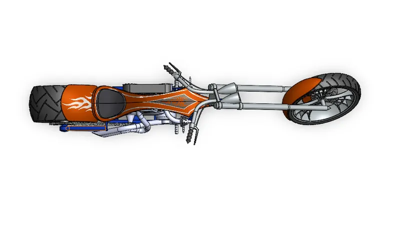
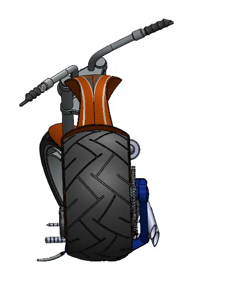
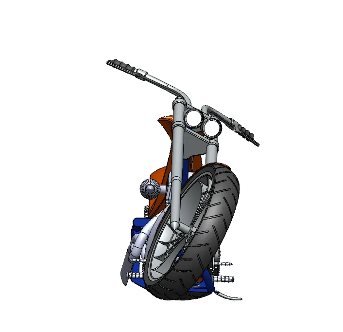
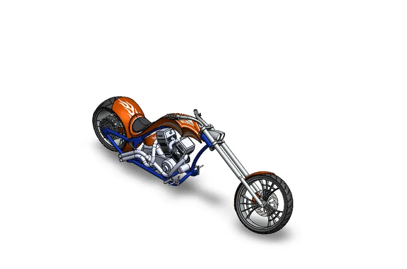
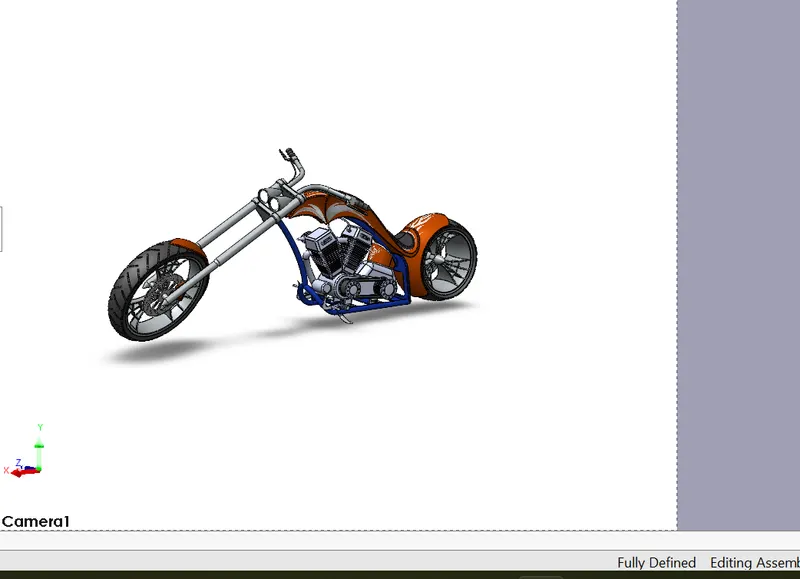
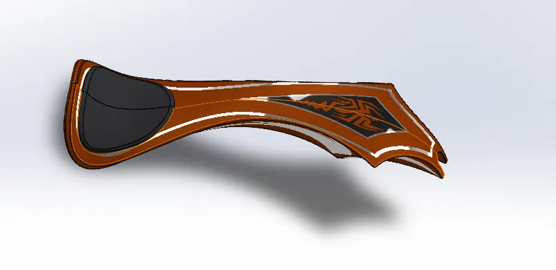
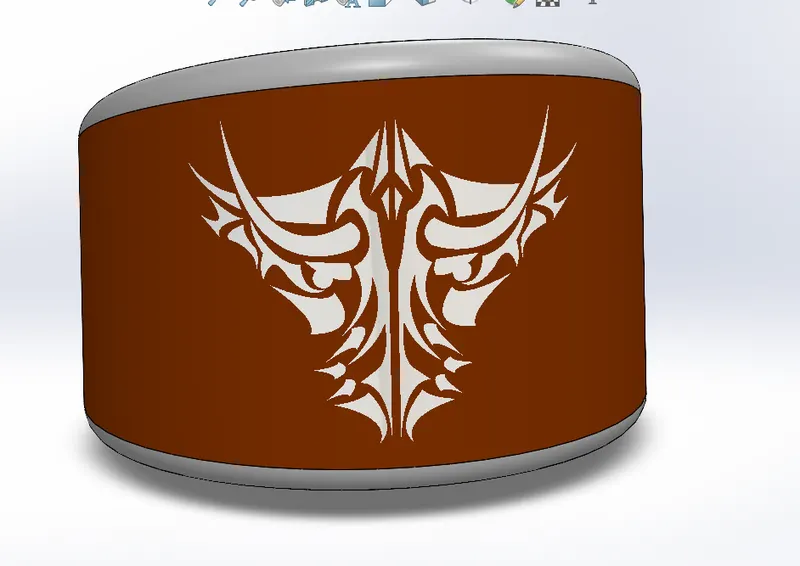
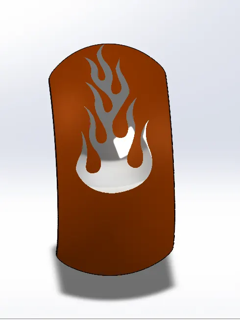
Decals : It means to add some picture in our parts to look cool our bike and also gives more attractive to our bike.
RENDERING:
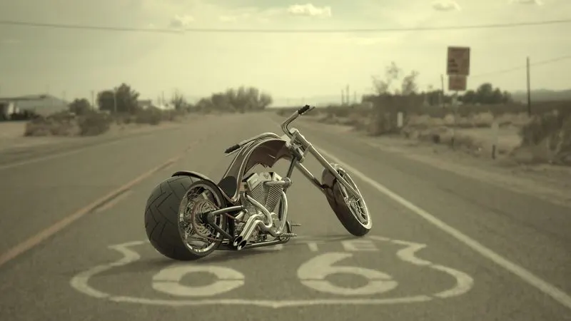
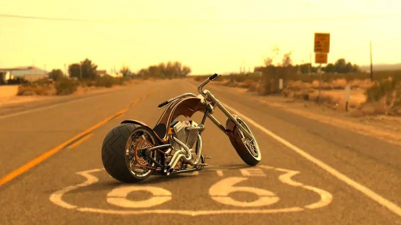
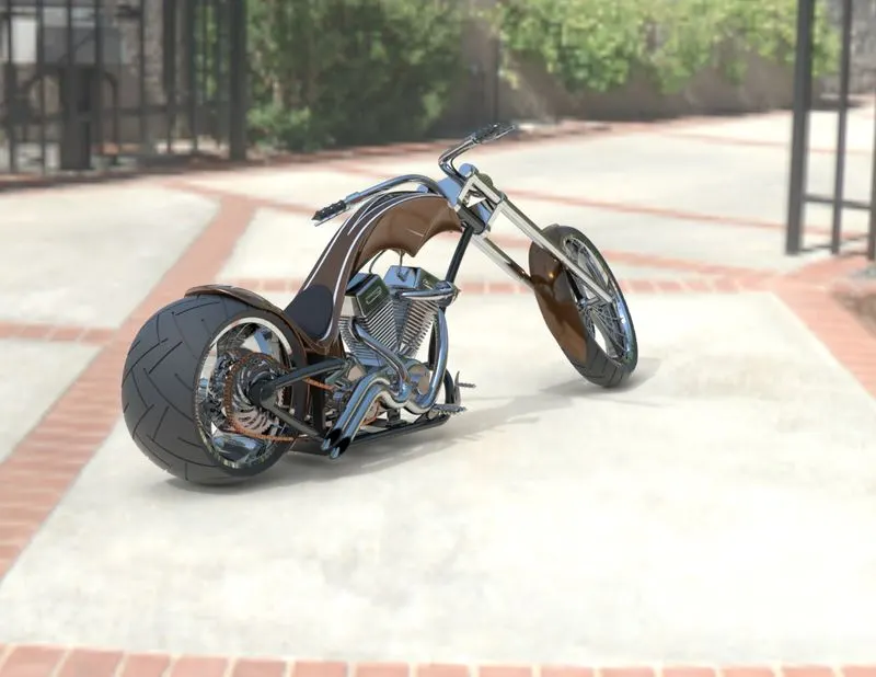
After assembly, we have taken our model to give some realistic view so that it looks smillar to our environment nature. Rendering basically done to gives lights , camera view , putting realistic colour. In solidworks rendering can be done in two ways that is photoview 360 and solidworks visualisation .
CONCLUSION:
Finally I have completed my american chopper with various sketch and feature tools in creating parts , assembly and rendering in solidworks software.
HERE IS GOOGLE LINK TO MY AMERICAN CHOPPER MODEL.
https://drive.google.com/drive/folders/1nY1tDFwr7uSWO92AqQiwMnNkcjbGDZBY?usp=sharing