Week 8 - Challenge 1 - Base Bracket Design
Aim: To Create the Base Bracket Plastic component through the given Class-A surface.
Objectives:
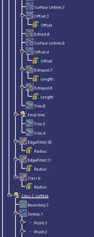
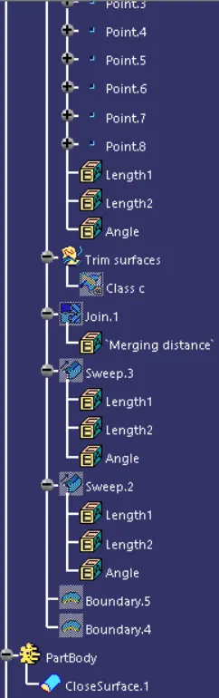
- Ensure Proper Tree Structure
- Geometrical sets should have a proper name based on the sketches present inside of it
- All the sketches should be created under the Geometrical set
- Use the Close Surface feature to make a solid body from the surface.
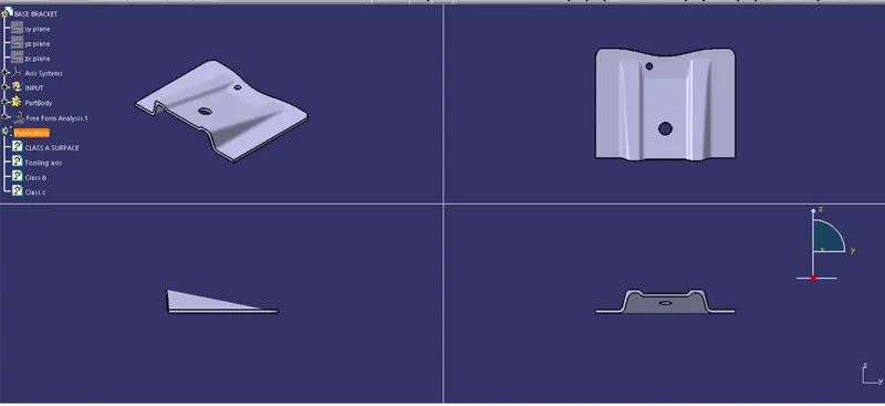
To start with is to download and open the below cat part file of the base bracket.
Base Bracket (Class A surface):
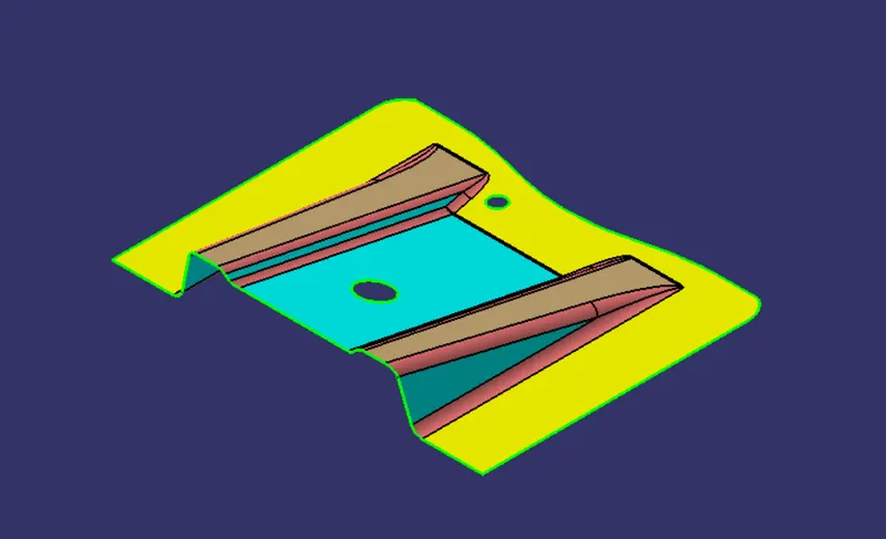
Now check the continuity of the surfaces using bounddary option. There should not be not gao between the surfaces.
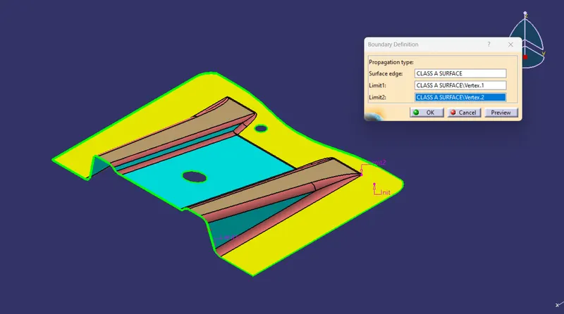
Once it is verified that there is no gap, next step is to create Tooling axis of the above model. Check visually for the direction of tooling.
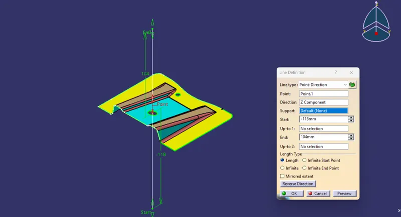
For that should create a dummy axis in any direction, here in Z direction.
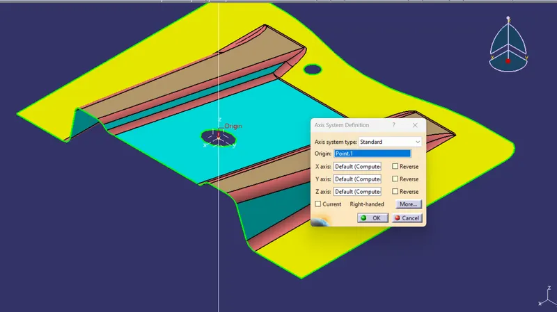
Before that create point so that the axis line can be created as shown in below figure.
Next create a reference axis in order to obtain the intersection line.
Go to Tools > Axis system, click the point created and deactivate the current axis option.
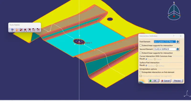
Now click intersect option  and click the xy plane of the created axis as first element and the class A surface as the secont element.
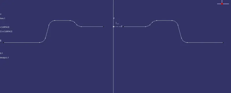
If we see the profile from the X direction we obtain a following view,
Now draw a line in approximate tooling direction i.e., along the walls of the bracket which might create a problem while tooling.
Click line > point - point and create the lines. Next create a bisecting line with the help of 2 lines created.
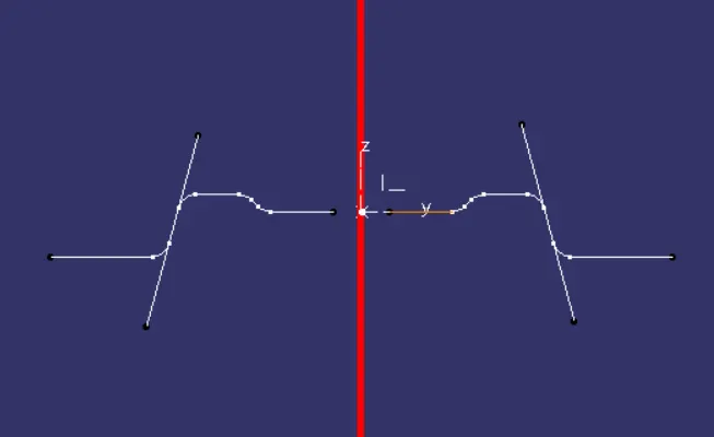
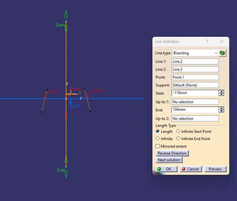
Name the loine in feature tree as "Tooling clearing X direction".
Similarly, we have to create a tooling axis in Y direction as shown below,
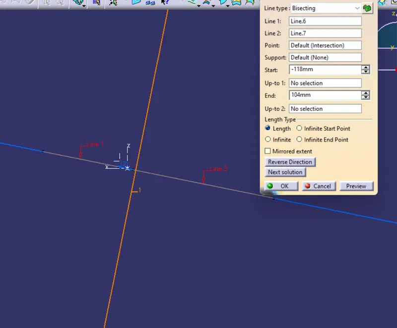
Name the loine in feature tree as "Tooling clearing Y direction".
Now since we have obtained two tooling axis onbtained from different ciew direction. Next steps is to create a common tooling axis with the help of bisect line creation option and selecting the two lines and a point as reference as shown below.
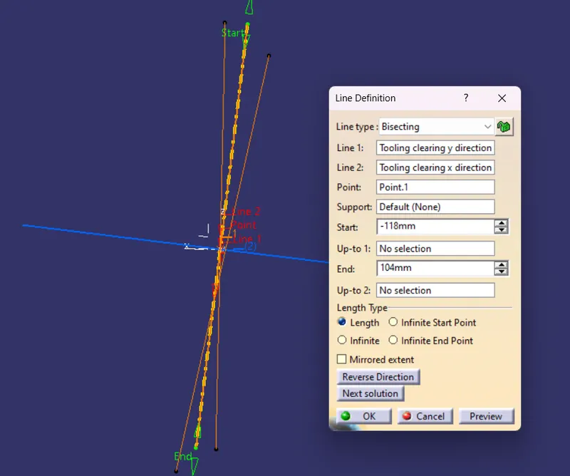
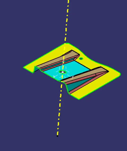
Since the tooling axis is created, now lets perform draft analysis.
Draft Analysis:
To peform the draft analysis we have to set the view parameters to material mode.
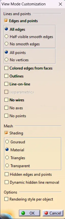
Now go to Insert > Analysis > Feature draft analysis.
Hold the compass and align along the tooling axis. Lock the compass and then click anywhere on the class A surface. If the whole surface change to green color, then the component is within the permissible draft limit.
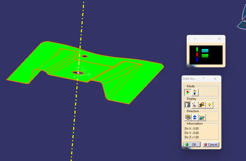
The dracft direction should be adjust to the molding axis using navigation compass.
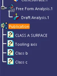
Publish the class A and tooling axis from Tools > publication and select the class A and tooling axis.
Class B surface creation:
First thing we have to do is to extract the ribs surface using extract tool  one by one.

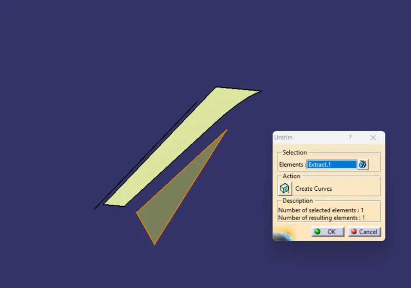
Next untrim all the surfaces using untrim  option. Select the surface to untrim one by one as shown below.
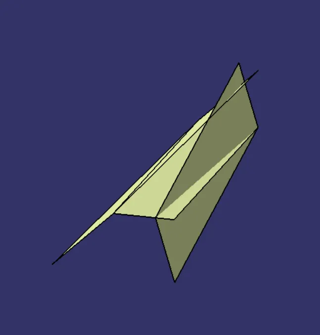
Extrapolate  the surfaces amd make sure that the continuity is curvature not tangency.
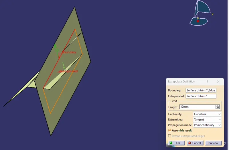
Using trim command, remove the unwanted parts and then offset the sureface to 2.5 mm as required and change the colour of the surface for reference. Name the geometrical set as Rib 1.
Similarly perform the above operations for Rib 2 also.
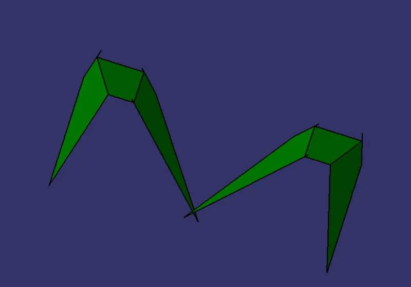
Now we have to extract the remaning surfaces and same procedure has to be followed with offset of 2.5mm.
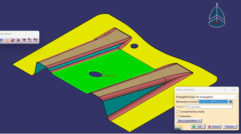
Once the surface is trimmed required fillet is applied to the sharp edges (Fillet = Thickness + outer fillet). And chande the colour of the surface for beteer understanding.
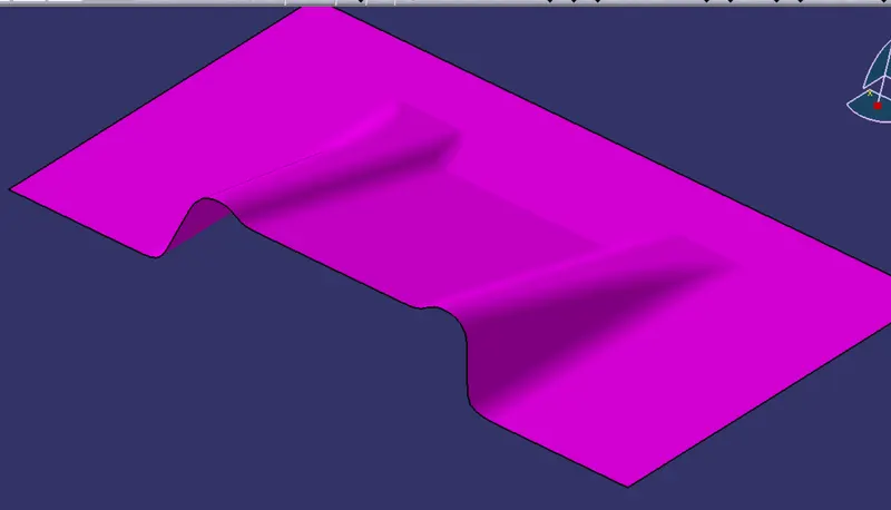
Publish the class b surface from Tools > publication and select the class b.
Class C surface:
Using boundary option extract the outer boundary as well as the inner hole edges.
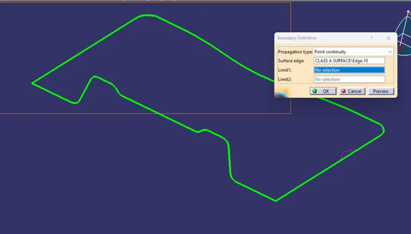
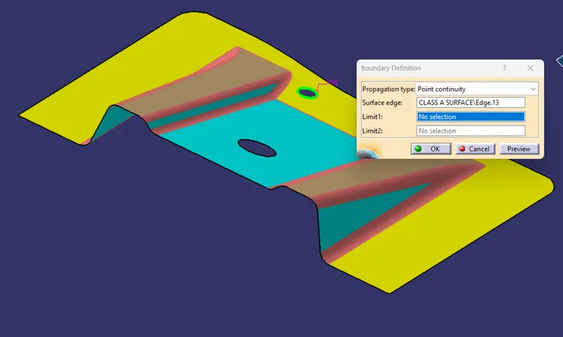
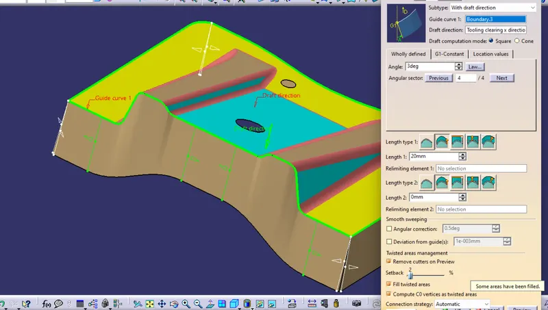
Now the boundaries using sweep surface and select sub type as sweep from draft angle and select the boundaries as first element and tooling axis as the direction. Click ok the surface is created.
Now join the created sweep surface with the class A surface.
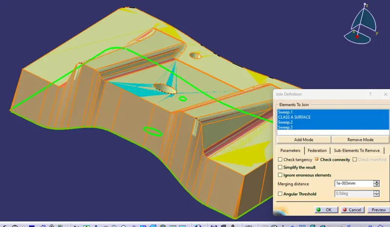
Next step is to trim the surface from the class B to obtain the class Surface.
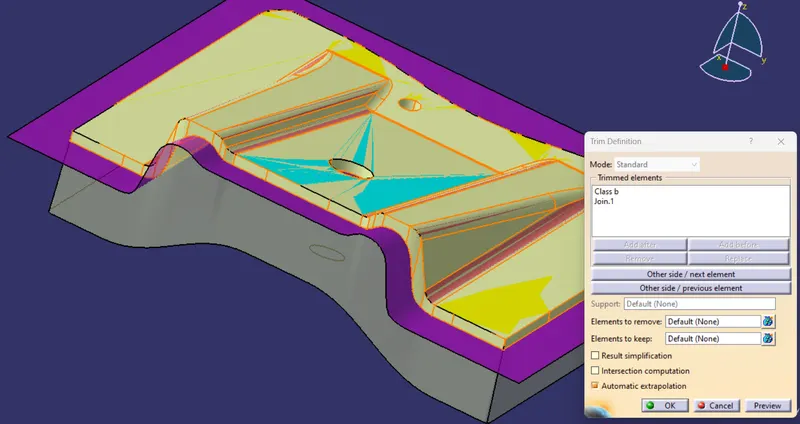
Publish the class C surface from Tools > publication and select the class C.
Final Body:
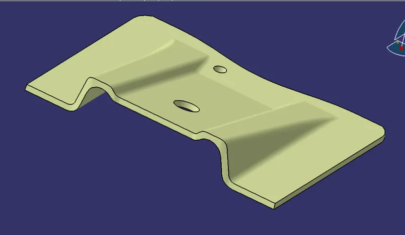
Click the close surface option and select the class c surface and click ok. THe solid body is created.
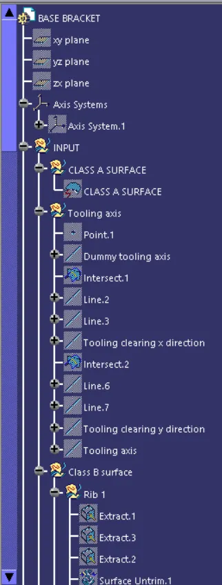
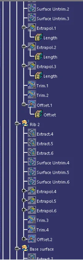
Expanded Feature tree:
Different Views: