Week 8 - Challenge 1 - Base Bracket Design
Aim : To understand the draft analysis in catia and how to used it and their importants.
Objectives : Create the Base Bracket Plastic component through the given Class-A surface. To begin with, the tooling axis for the given Class-A Surface should be created meeting the requirements of the draft angle and at the end perform the Draft analysis on the model.
Descripstions :
Draft Analysis :
The draft analysis technique is used to analyze whether our part model created in CAD is manufacturable based on the draft condition applied. Here the part should get easily removed from the panel dies (in case of Sheet metal part) or Mold (in case of plastic).
No parts can be ejected from the tool if it is having a straight 90-degree profile from its base surface. A small draft angle is provided to each and every area of the component in order to get easy removal of the component from the tool.
Here we are providing a direction in which components should eject in order to get easy removal of components from the tool. In other words, it also lets us know whether the model is having a draft angle and how much is the draft angle from the tool direction.
When designing a part, apply as much draft angle as possible a general rule of thumb is 1 degree of draft per 1 inch of cavity depth, but that can change with the aforementioned factors.
General Guidelines:
1. 0.5 degrees on all vertical faces is strongly advised.
2. 1 to 2 degrees works very well in most situations.
3. Three degrees is minimum for a shutoff (metal sliding on metal).
4. Three degrees is required for light texture.
5. Five or more degrees is required for heavy texture.
What is Class A, B & C SURFACE ?
A-Class Surface
A-Class surface is a term used in plastic product design. That means the surface of a component that is smooth( aesthetic) or visible side to the human eye after the part is assembled. it refers to those surfaces which are visible and abide by the physical meaning of a product.
B-Class Surface
B-Class surfaces are the secondary surfaces that you can see sometimes, but are less important, such as the inside of your glove box, ashtray, etc... These must be smooth and "error-free" as well but are not held to the standards that class A surfaces are. it also means the thickness of a part.
C-Class Surface
C-class surfaces are the backside surfaces that can have tool marks, flash, and other imperfections without hurting appearance, function, etc...it also means A and B combined to give C surface.
Procedure for Features Draft Analysis
Here is we used the catia part file which is provide by this challenge and create the tooling axis before the Draft Analysis so 1st we create the piont on circal used that piont we create dummy axis and this axis used to selected plane in that direction shows all objectes clearly with holes, internal hind command easily so we can easily analysis draft is correct or not
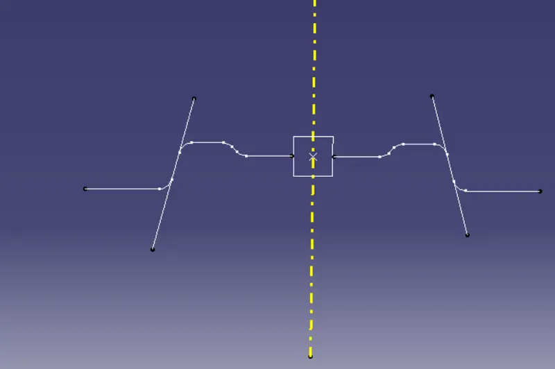
after that we interset the class A withe that plane so we get the profile our object and used this profile we create two line in that we we bisect that line this bysecting line is required tooling axis direction than we create our tooling axis as shown in below
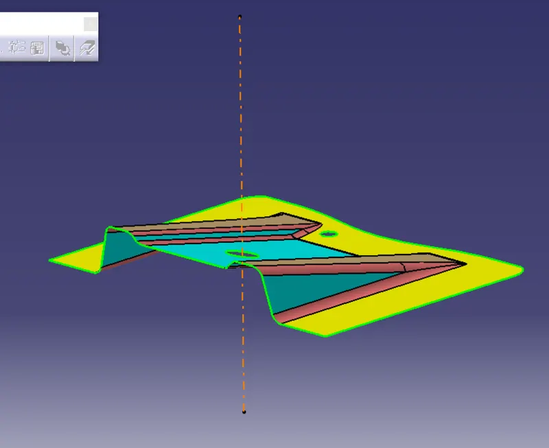
than we go to the draft analysis
Go to menu bar > select insert > Analysis > Feature Draft Analysis
used above path we goto in a draft analysis section in that 1st step is align the compass z-direction with the main tooling axis which we created in the previous steps. below images show the dratf analysis and adjusting on commpass on tooling axis
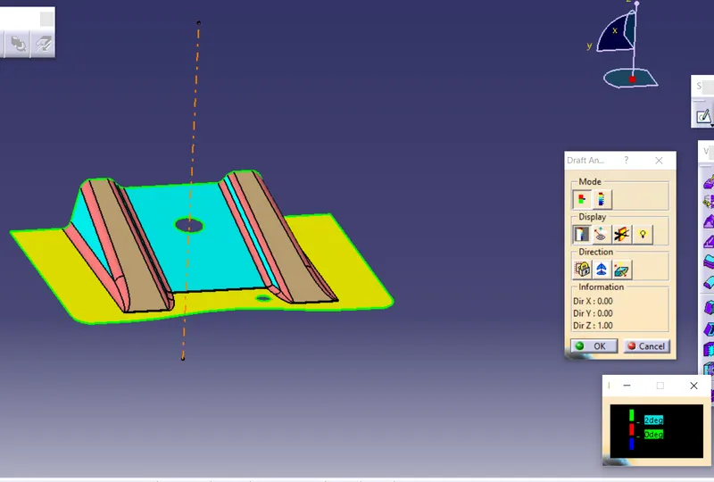
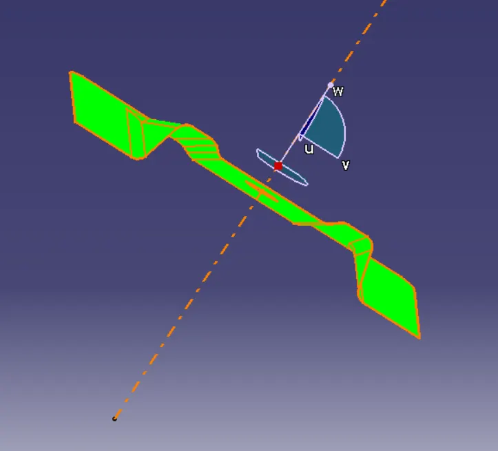
we set the draft angle value is 3 if the value of draft angle is greater than 3 so all draft angle value is greater than given angle means design is safe we can able to manufature this components
than we create the B and C surface
Procedure for design A-Class, B-Class, and C-Class of Base Bracket :
B surface :
Extract Rib then untrim, Extrapolate and trim the base bracket
Extract 2nd rib same as rib 1.
offset rib 1 and rib 2 by 2.5mm. images shows in below
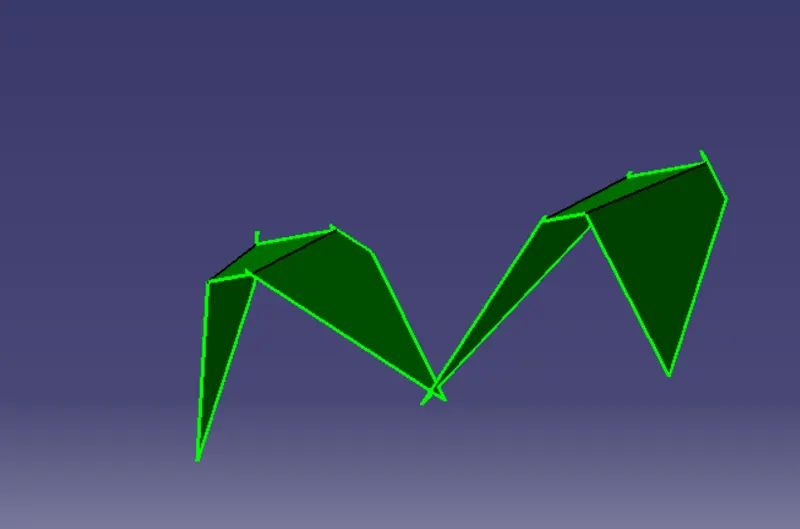
Extract and offset both the supportive base surface than untrim them and extrapolate 10 mm and offset by 2.5mm. than trim with rib 1 and 2 than again trim that 1st trim with secon supportive base offset and get the b surface object than Apply Fillet all neccessary portion with required dimensions and final fillet rename as B-Class surface. below images show the B surface
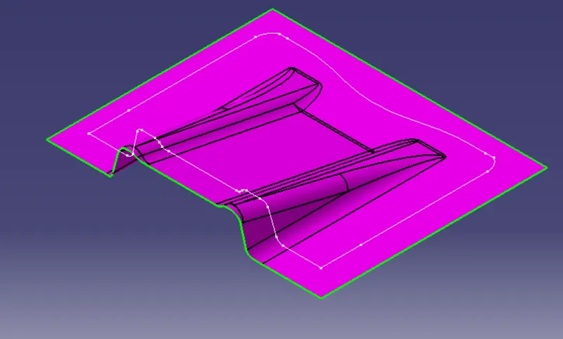
C-Class Surface
here is we create the boudary for Class A surface than sweep it 3-degree downside with draft direction with tooling axis than we create hole which is mention in a surface same method create theire boundary than sweep it with draft direction after that we untrim it with B surface we get final ouputs before that we joint it sweep and trims than holes create one untitis. below images we get c surface
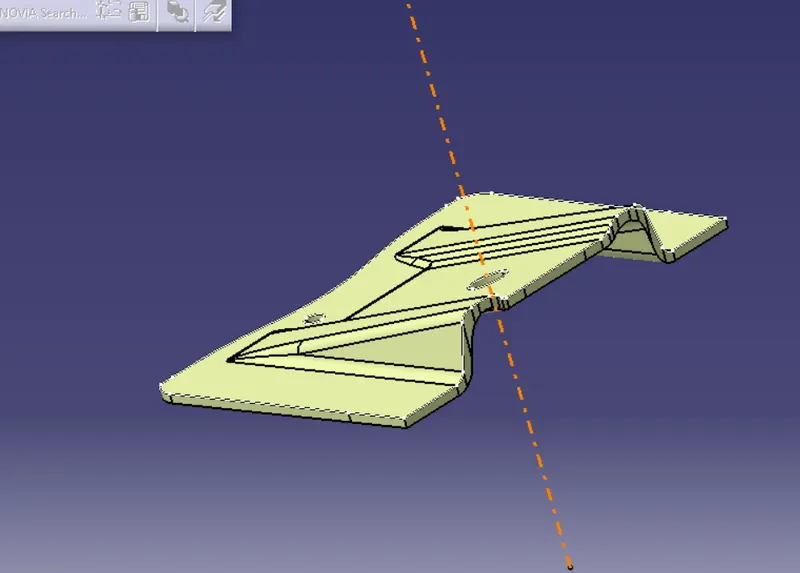
than we go to part modelling go to colse surface create the solid body.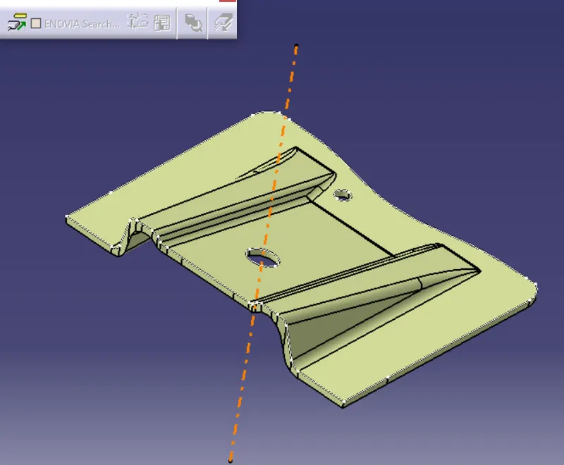
Notes : in this challenge we attch the catia part files which is mention all thinks that can explain in above pls refer it.