Week 8 - Challenge 1 - Base Bracket Design
Aim :
To Create the Base Bracket Plastic component through the given Class-A surface.
Objectives :
- To begin with, the tooling axis for the given Class-A Surface should be created meeting the requirements of the draft angle and at the end perform the Draft analysis on the model.
- Tree Structure
- Ensure Proper Tree Structure
- Geometrical sets should have a proper name based on the sketches present inside of it
- All the sketches should be created under the Geometrical set
- Use the Close Surface feature to make a solid body from the surface.
- Publications: Use the publication option and publish the below
- Tooling Axis
- Class A, B, and C surface
- A detailed report should be done explaining the draft analysis and the tooling axis creation.
- An explanation should be given on the way of creating the tooling axis, particularly the Bisecting method.
- Submission in challenge box
- Below images/screenshots should be inserted into the challenge box
- Screenshots of the Draft analysis report for both the given Class-A surface and the final plastic component
- Image of the complete Draft analysis
- Images of the color scale variant
- Screenshots of the solid model with the proper color code of the draft angle in various orientations (Isometric, Front, Side, and Top View)
- Submission as an attachment
- CATpart should be submitted as an attachment using the below Browse option.
Procedure :
- 1.First Thing is open the CATIA V5.
- 2.Open the given BAE BRACKET CATPART file part then check if the geometrical set is properly arranged or not.
- 3.Then go to the Surface workbench
- 3.Give the proper Tooling Axis.
- 4.After that work on the Base Bracket Geometrical Structure.
- 5. Ensure to check the bondaries & join them properly.
- 6.Make sure that proper dimensioning is necessary
- 7.Finally check if it is Iso Constrained (Fully Constrained) or not.
- 8. By Using Surface workbench to thicken the surface & Close them properly.
Let We Discuss in Detail Manner in Step By Step :
Class A Surface :
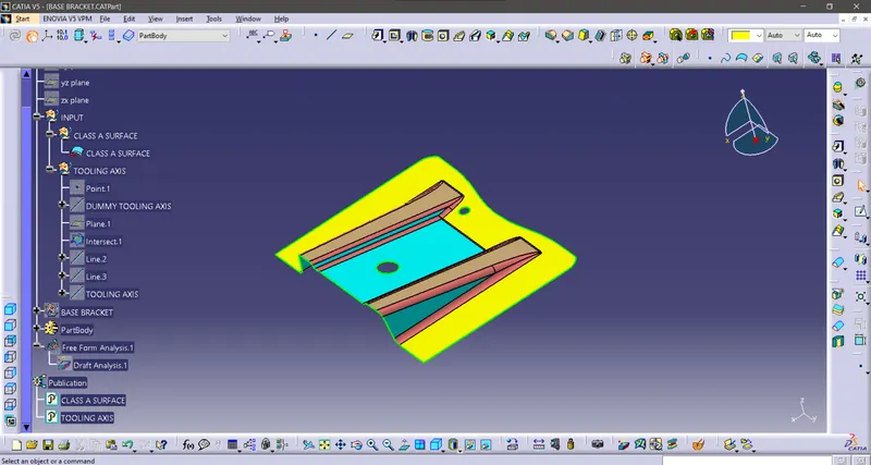
Already we have the class a surface Just Load it into the catia From given task. Observe Carefully angles & Plane Surfaces on it As shown in figure given below.
Tooling Axis :
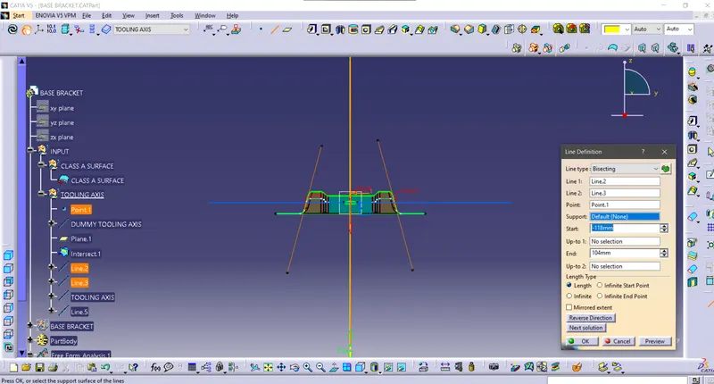
First We Need to create a Point on Class A surface Where the proper Place which should be parent on whole surface so we are selecting the big hole on Class A Surface which was inclined on it.
After that a plane which was perpendicular to the plane.
Ater that create a dummy tooling axis & then intersecting the class a Surface.
Now draw the 2 lines on both sides of intersceting drawing which is some what parallel to the intersecting drawing.
Bisecting Line:
In Geometry, a 'Bisecting line' that divides the line into two different or equal parts. It is applied to the line segments and angles.
Then Create a bisecting line on those 2 lines Which we calles as bisecting line & Hide unwanted surfaces As sown in fgure below.
Publications :
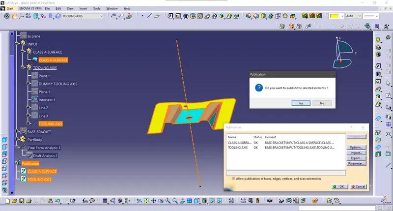
slecting the sorfaces what we needed so we are selecting the Class A Surface & Tooling Axis after that go to the tools & Select the publication Click yes & Click ok, then we got the publication on the tree As shown in figure below.
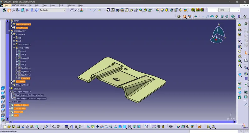
So Total Publications We have
Tooling Axis
Class A B & C Surfaces As shown in figure below
Draft Analysis :
So lets discuss about the draft analysis
The Draft Analysis allows the user to easily analyze a part for proper draft angle. A Draft Angle describes the amount of taper for molded or cast parts perpendicular to the parting line.
We have 2 modes on the draft analysis Quick & Full analysis respectively.
Under the Display option we have Show are hidden the Color Scale, Analysis under the running point, No Highlight representation & Light effect.
Under the Direction option we have lock or unlock the direction, Compass & Invert.
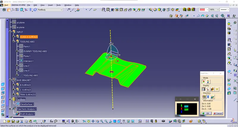
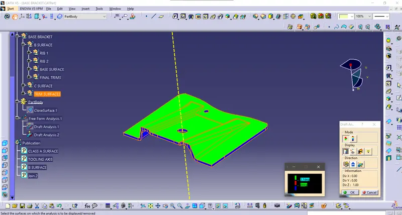
So According to the practical Usage there Should be 3degree of angle mostly acceptable, by considering these option we have to test our given & Final Components Draft analysis.
Class A Surface had Drafted & analysed by considering the inverse directon of Z, As shown in figure below :
Final Plastic Component had Drafted & analysed by considering the inverse directon of Z, As shown in figure below :
Complete Draft analysis :
Change the mode to Complete Or Full analysis Mode :
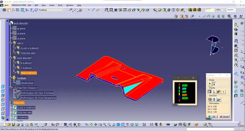
So Lets Start With the,
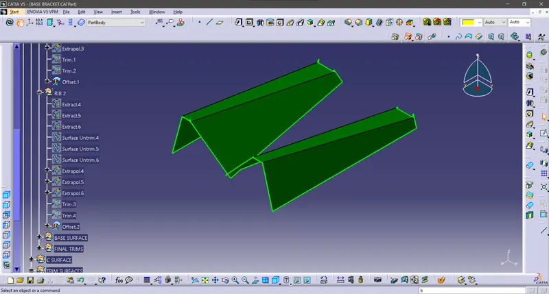
Base Bracket B Sutface RIB 1 & RIB 2 :
We have to Extarct the Components of Class A Surface & Do 'Surface Untrim' them after that Trim & Offset What we want, As shown in Figure Below.
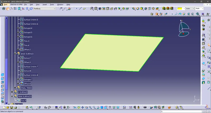
Base Surface :
Similaraly we have to Construc the Base Surface From Class A Surface As shown in figure below.
B Surface :
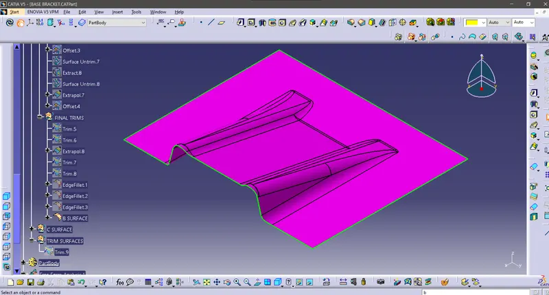
By taking the outputs of RIB 1 & 2 & Base Surfaces & Also Class A Flat Surface Extraplolte & Untirim & Trim the Surfaces Then we got the B Surface as shown in figure below.
C Surface :
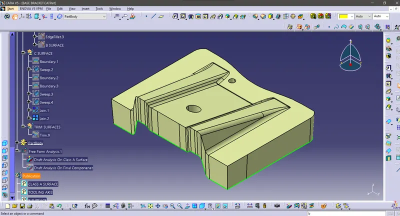
while constructing the C Surface We have to take the Boundaries Of Class A & Swept them & Trim & Join them then we Got the C Surface as shown in figure below.
Final Trim :
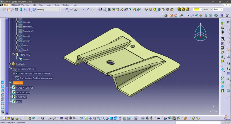
Trim the C Surface with Class A Surface then we Got the Final component as shown in figure below.
CLOSE SURFACE SOLID BODY :
Go to the part design workbench & Click the close surface command & click the final trim surface component then the close surface solid body formed as shown in figure below.
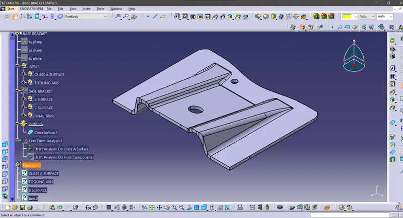
Hence observe that the above screenshots have Fully Defined, Expanded Tree Structures & Snaps in various orientations.
Conclusion:
Successfully Created the Base Bracket Plastic component through the given Class-A surface.
The CATPART files or Zip File was attached below.