Week 8 - Challenge 1 - Base Bracket Design
- Submission Requirements
- Screenshots of the Draft analysis report for given Class-A surface
- Image of the complete Draft analysis
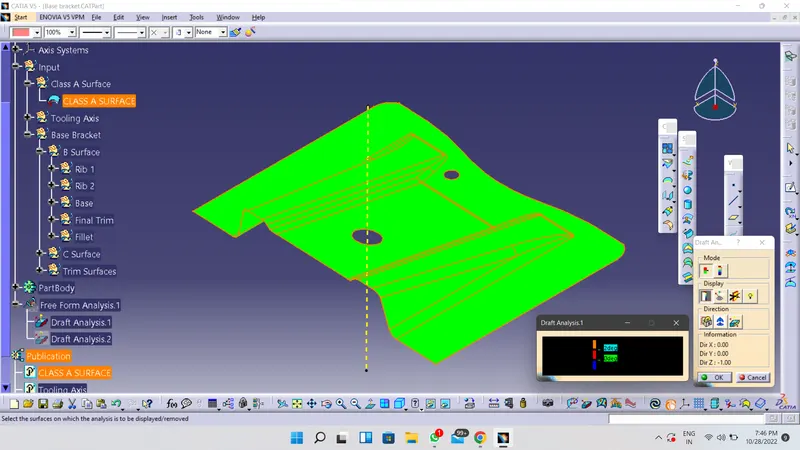
- Images of the color scale variant
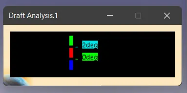
-
Screenshots of the Draft analysis report final plastic component
- Image of the complete Draft analysis
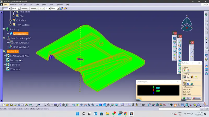
- Images of the color scale variant
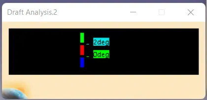
- Screenshots of the solid model with the proper color code of the draft angle in various orientations (Isometric, Front, Side, and Top View)
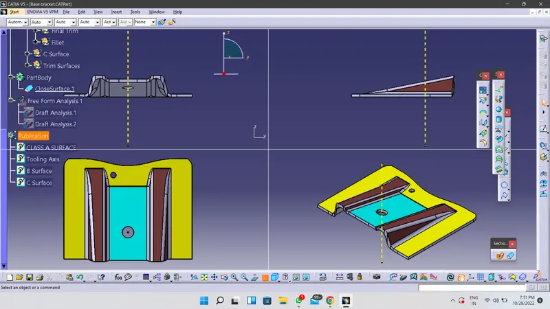
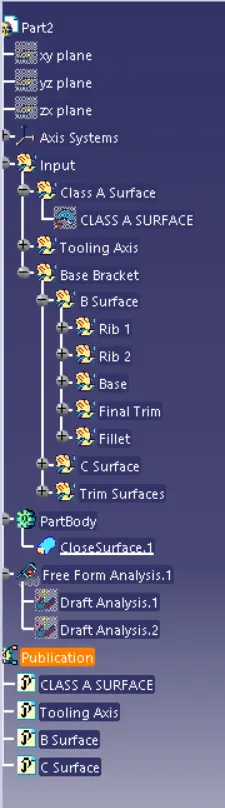
Expanded Tree Structure
REPORT
Tooling Axis
- Tooling defines the opening and closing of the core and cavity resulting the formation of mold cavity where the molten plastic is injected and allowed to cool
- To define the tooling axis we initially sppose to check the ease of tooling axis for opening and closing of the core and cavity normal to plane for all 3 planes
- Consider the hole, Ribs, Slots and other Enginnering to check possible Dummy tooling axis
- After the decideing the Dummy tooling axis
-
1 Take intersection for the plane parallel to Tooling axis 2 Draw line from intersection to check wether intersecting with tooling axis 3 After draw a bisecting line between two lines drwn on intersection 4 Define the bisecting line as tooling axis - Use Feature draft analysis by providing pulling direction, surface, draft angle and draft angle direction
- Green results are ok, blue results shown negative draft (for angle use colour scale)
- Once tooling axis is ok procees the B Surface and C Surface by offseting class A Input
Attachment -
1. Week 8 - Challenge 1 - Base Bracket Design