Week 8 - Challenge 1 - Base Bracket Design
Draft Angle
A draft angle refers to that slant applied to the sides of most features of injection molded parts. Positioning of the injection angles is such that they run towards the direction of the mold's pull and parting line. They help to release the molded parts from the mold easily.
Tooling Axis
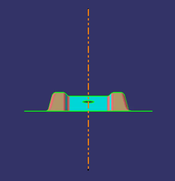
The axis through which the core and cavity are going to move and operate is the Tooling axis (z-axis).
Creation of Tooling axis using the bisecting method
Step1: Acquire the cross-section outline of the component from the x-direction using the intersection command. Select the component and the appropriate plane and click 'OK' in the command.
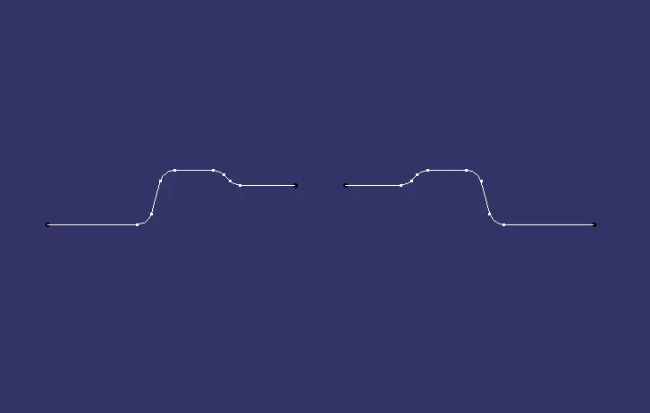
Step3:
Extending the line which is closest to the tooling axis at being parallel to it and a point at the centre of the cross-section.
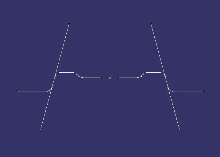
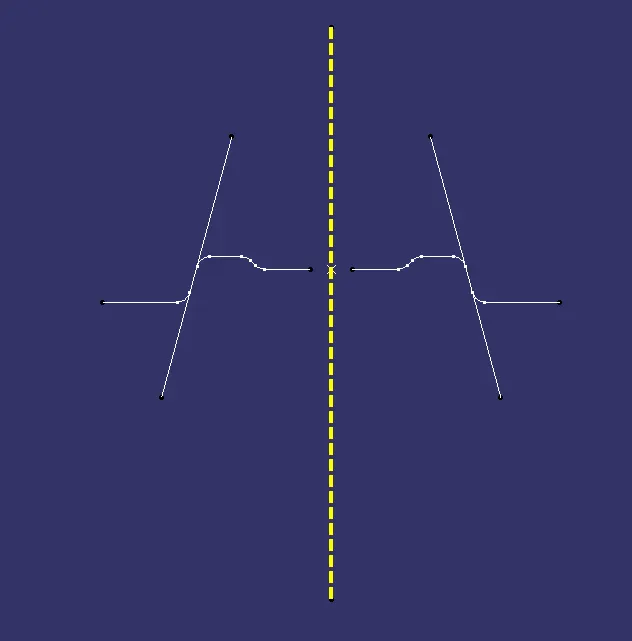
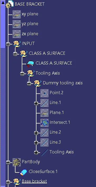
Step4: Create a Dummy tooling axis through the point for reference while creating the actual tooling axis.
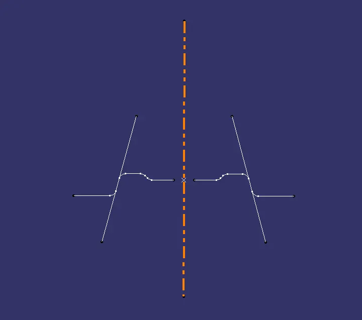
Step5: To create the actual Tooling axis we shall create a line using the bisecting method/line type and select both the extended lines as Line 1 and 2. For the point, select the point at the centre and click Preview. After the Preview select the Vertical line as the final output for the Tooling Axis.
Draft Analysis
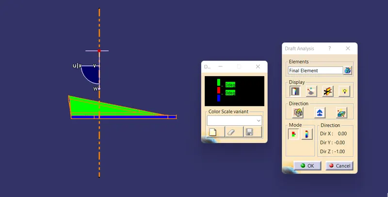
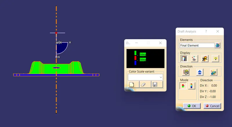
The Draft Analysis command enables you to detect if the part you drafted will be easily removed. This type of analysis is performed based on color ranges identifying zones on the analyzed element where the deviation from the draft direction at any point, corresponds to specified values.
For the color ranges there are 3 colors presented in a simpler legend called the quick analysis mode. Beginning with Green, Red and Blue colors corresponds to the draft angle range of above 3 degrees, 0 to 3 degrees and below 0 degrees respectively.
The ideal value of the draft angle is set at 3 degrees and accordingly the component should be representing the green colour all over the surface which indicates the appropriate value.
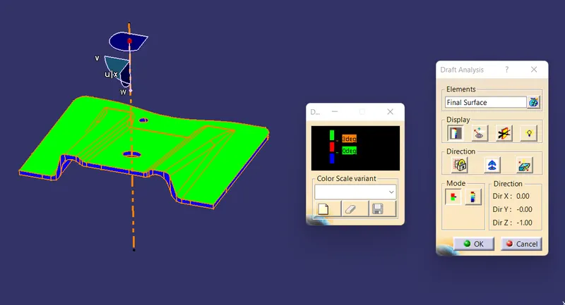
Since the B surface is on the negative side of the ground plane it is highlighted in the blue colour. We must flip the draft direction using the inverse draft direction option and check for the green colour.
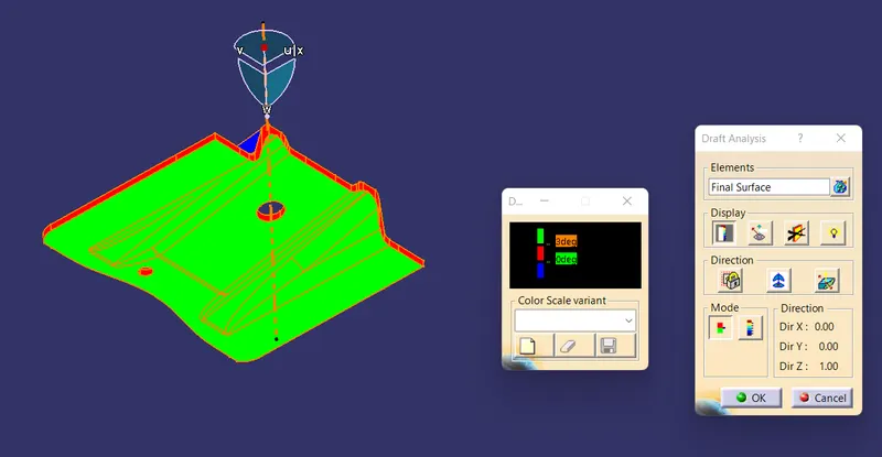
1. Class A surface
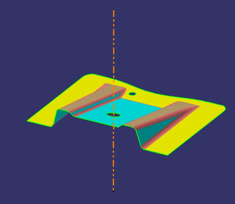
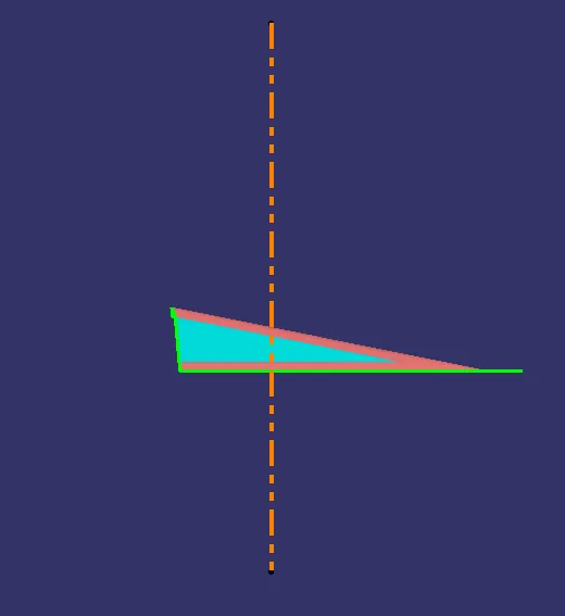
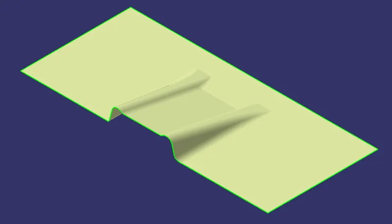
2. B surface
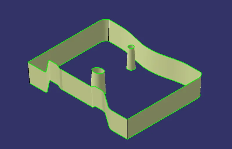
3. C Surface
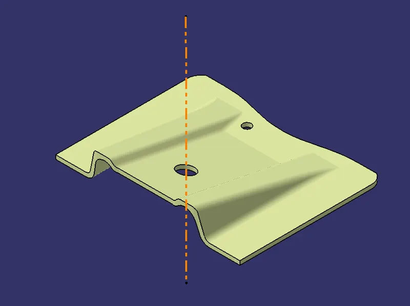
4. Final Element
5. Close Body
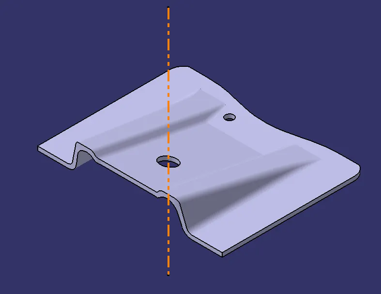
6. Draft Analysis of Class A Surface
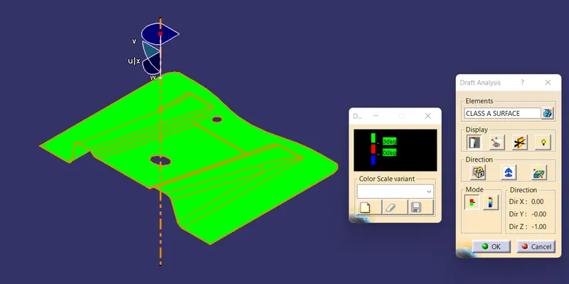
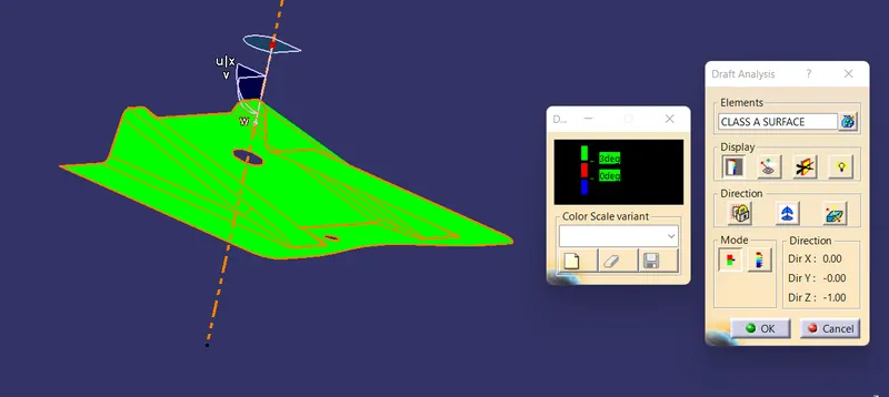
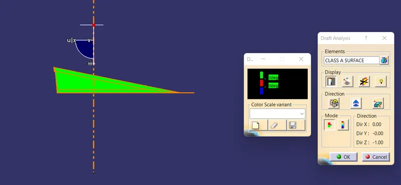
7. Draft Analysis of the Final Element
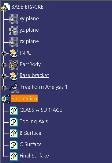
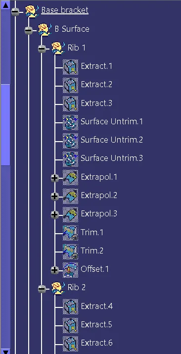
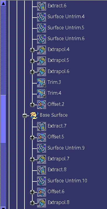
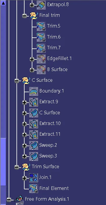
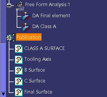
8. Tree Structure
END.