Week 8 - Challenge 1 - Base Bracket Design
AIM:
To create the Base Bracket Plastic component through the given Class-A surface. To begin with, the tooling axis for the given Class-A Surface should be created meeting the requirements of the draft angle and at the end perform the Draft analysis on the model. Thickness of Plastic Part - 2.5 mm.
DRAFT ANALYSIS AND TOOLING AXIS :
Tooling Axis:
In draft analysis we want to check whether the part that we have created is having an ease of manufacturability or not .Draft is a kind of angle that is provided on the surface of the part so that it will produce minimum amount of friction with core and cavity .
Minimum draft angle that we like to give in case of plastic parts is of 3 degrees generally.
For draft analysis there are some steps that we generally follow:
1.We first take the Class A surface. As shown in figure.
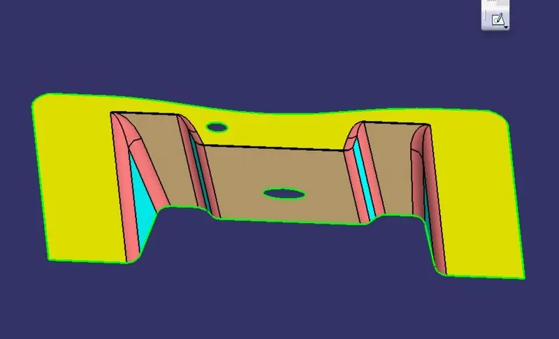
2.We will check connectivity of the surface , we can check it by join command or by using boundary .while checking we observed that there are only 3 boundaries one is outer then the other two are the inner circles.
3.Tooling Axis ,It is the axis along which the mould opens and closes and we want easy removal of material after its solidification .
Here after verification we observed that along X and Y axis we will be having problem Hence we selected Z axis for our dummy tooling axis and created Dummy tooling axis along Z direction as shown.
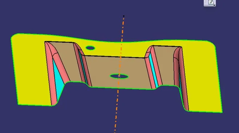
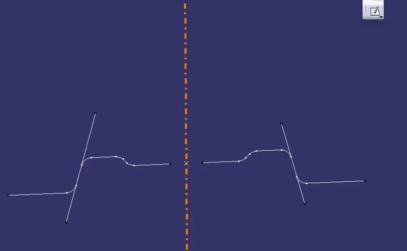
4.Now we wil take intersection of the surface with the plane across tooling axis.
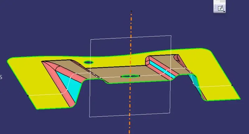
5.Then we will draw two lines at a particular slope as shown in figure and we will take the bisection of these two lins .that will be our Tooling axis.
Draft Analysis:
As we already know that the draft is provided on parts for easy removal of plastic parts to avoid parts from getting damage as well as to reduce the cost.
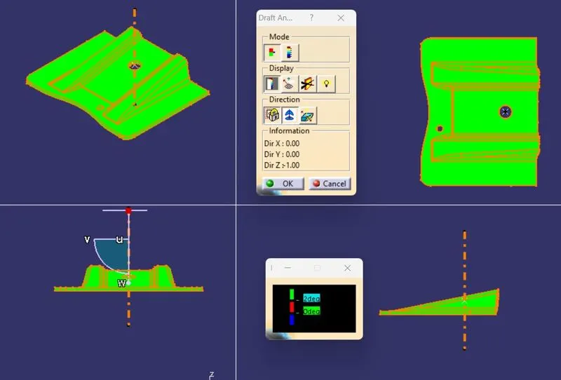
1.Select the class A surface along with tooling axis ,then go to draft analysis tool .
2.Put the axis system across the tooling axis and lock it .as shown in fig.
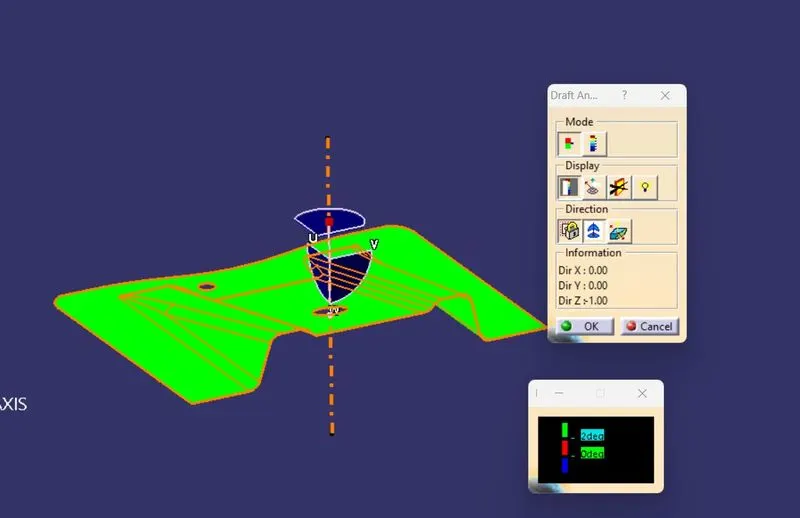
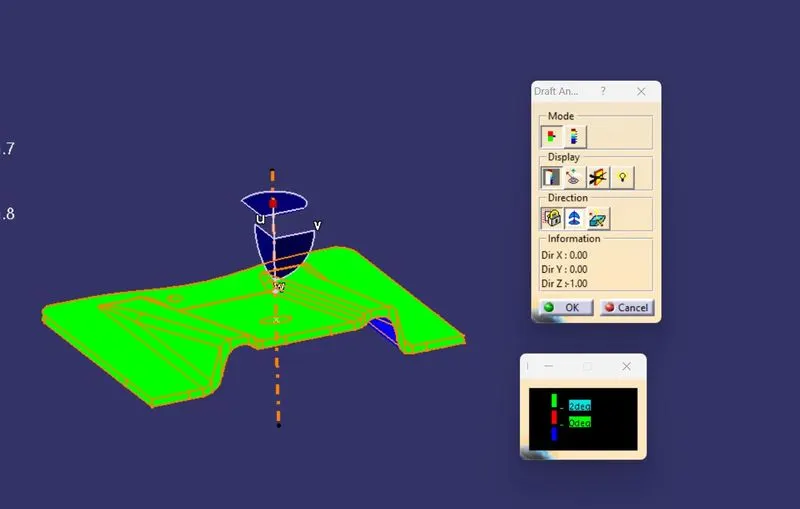
3.Now click on the part surface it will show green color , which mean the draft is more than of 3 degree .Hence it passes.
CREATION OF CLASS B SURFACE:
Class B surface here we have created by using command extract and extrapolate of the Class A surface. As shown in fig.
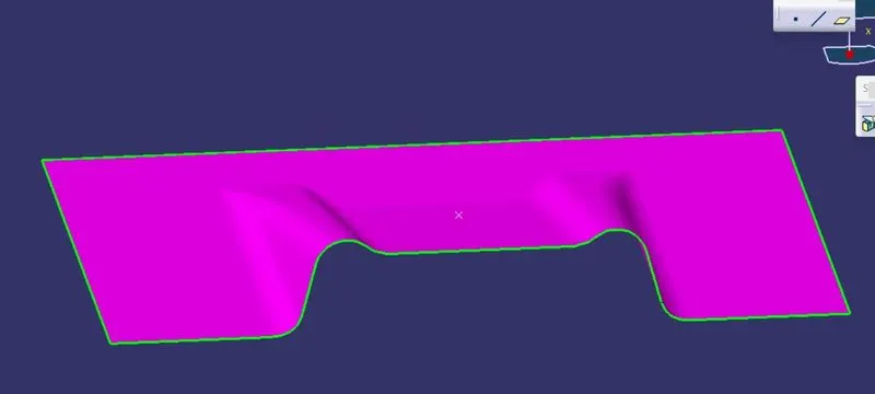
Offset command is used here to provide a thickness of 2.5 mm.
CREATION OF CLASS C SURFACE:
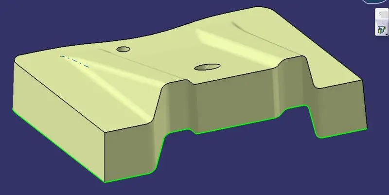
It is created by using the boundary of class B surface and using sweep command , we extended it further to ease in Trim operation.
SOLID BODY CREATION USING CLOSE SURFACE OPTION:
Now we will trim the B and C surface and after that we will use bounday command to check whether there is any unwated opening or not.
Then we will use Close surface option and we will create a solid body.
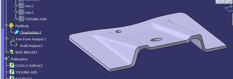
DRAFT ANALYSIS OF FINAL PLASTIC PART:
Screenshots of the solid model with the proper color code of the draft angle in various orientations (Isometric, Front, Side, and Top View):