Week 8 - BlockMesh Drill down challenge
First we need to know which problem we are going to solve and we need to identify which tutorial in openfoam is useful to solve our problem.
For that we need to grind through all the tutorials available and identify the required one
The above problem is to solve incompressible laminar viscous flow through a backward facing step geometry
For that we need to take the tutorial named cavity in incompressible folder .
Lets see how we need to do it
First we will see about few commands present in OPEN FOAM
cd - used to navigate into any directory
ls - used to see the folders present in a particular directory
cp - used to copy a file
cp -r - used to copy a directory
tut - Directly navigate into tutorials folder
sol - Directly navigate into the solver folder
gedit - used to open code files and gives us freedom to edit the codes as per our problem statement
Now by using the above commands we will solve the problem using the open foam
1. First open the terminal and press ls to see in which current folder we are present .
2. Type tut to navigate into the tutorials folder .
3. Type ls to see the files present in the tutorials folder.
4. Type cd incompressible to navigate into the compressible folder.
5. Type ls to see the files presnt .
6. We fill find the folder named cavity which we need to use .
7. Copy the tutorial to the $FOAM_RUN folder because we do not want to mess the official files present .
8. So to copy and paste it into the $FOAM_RUN folder use command cp -r cavity/$FOAM_RUN/cavity_2
9. Now we need to edit the copied files and run the simulation
10. First we need to change the geometry , So for that we need to find the blockMeshDict file .
11. Type cd system to go into the system file .
12.In system we will find the file blockMeshDict file which is used to edit the geometry and give the inputs to the type of walls
The vertices are edited so that the vertices represent the required geometry and the type of the mesh is given as hex and the type of walls also edited in the blockMeshDict file
The geometry of the cavity is
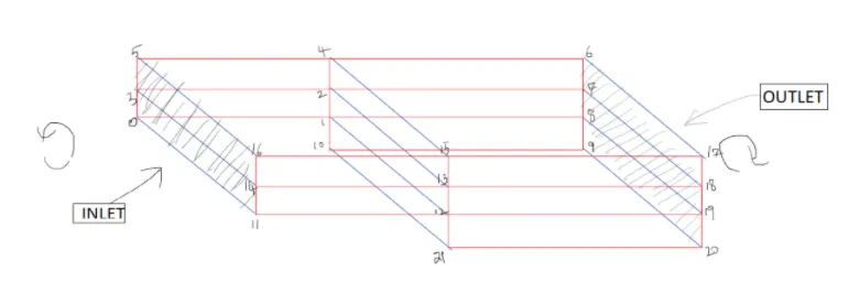
13. The blockMeshDict file is edited in the following way
/*--------------------------------*- C++ -*----------------------------------*\
  =========                 |
  \\      /  F ield         | OpenFOAM: The Open Source CFD Toolbox
   \\    /   O peration     | Website:  https://openfoam.org
    \\  /    A nd           | Version:  8
     \\/     M anipulation  |
\*---------------------------------------------------------------------------*/
FoamFile
{
    version     2.0;
    format      ascii;
    class       dictionary;
    object      blockMeshDict;
}
// * * * * * * * * * * * * * * * * * * * * * * * * * * * * * * * * * * * * * //

convertToMeters 0.01;

vertices
(
    (0 0 0)            // vertex point 0
    (8 0 0)            // vertex point 1
    (8 0.5 0)          // point 2
    (0 0.5 0)          // point 3
    (8  1  0)          // point 4
    (0 1 0)            // point 5
    (20 1 0)           // point 6
    (20 0.5 0)         // point 7
    (20 0 0)           // point 8
    (20 -1 0)        // point 9
    (8 -1 0)          // point 10

     (0 0 0.1)       // vertex point 11
    (8 0 0.1)        // vertex point 12
    (8 0.5 0.1)      // point 12
    (0 0.5 0.1)      // point 14
    (8  1  0.1)      // point 15
    (0 1 0.1)        // point 15
    (20 1 0.1)       // point 17
    (20 0.5 0.1)     // point 18
    (20 0 0.1)       // point 19
    (20 -1 0.1)    // point 20
    (8 -1 0.1)      // point 21

);

blocks
(
    hex (0 1 2 3 11 12 13 14) (200 10 1) simpleGrading (1 1 1)
    hex (3 2 4 5 14 13 15 16) (200 10 1) simpleGrading (1 1 1)
    hex (1 8 7 2 12 19 18 13) (200 10 1) simpleGrading (1 1 1)
    hex (2 7 6 4 13 18 17 15) (200 10 1) simpleGrading (1 1 1)
    hex (10 9 8 1 21 20 19 12) (200 10 1) simpleGrading (1 1 1)
);

edges
(
);

boundary
(

    inlet
    {
       type wall;
       faces
       (
       (0 11 14 3)
       (3 14 16 5)
       );
       }

    outlet
    {
       type wall;
       faces
       (
       ( 8 7 18 19)
       (9 8 19 20)
       (7 6 17 18)
       ) ;
       }

     frontAndBack
     {
         type empty;
         faces
         (
         (0 3 2 1)
         (3 5 4 2)
         (10 1 8 9)
         (1 2 7 8)
         (2 4 6 7)

         (11 12 13 14)
         (14 13 15 16)
         (13 18 17 15)
         (12 19 18 13)
         (21 20 19 12)
         );
         }

     noslipwalls
     {
       type wall;
       faces
       (
       (4 5 16 15)
       (6 4 15 17)
       (1 10 21 12)
       (0 1 12 11)
       (10 9 20 21)
       ) ;
       }
);

mergePatchPairs
(
);

//
14. In blockMeshDict file we have given inputs to the geometry and the boundary conditions
15. Now we will edit controlDict file so that we can give the timesteps we need and the number of time steps required to captutre the effect of pressure and velocity
The control Dict file is edited in the following way
/*--------------------------------*- C++ -*----------------------------------*\
  =========                 |
  \\      /  F ield         | OpenFOAM: The Open Source CFD Toolbox
   \\    /   O peration     | Website:  https://openfoam.org
    \\  /    A nd           | Version:  8
     \\/     M anipulation  |
\*---------------------------------------------------------------------------*/
FoamFile
{
    version     2.0;
    format      ascii;
    class       dictionary;
    location    "system";
    object      controlDict;
}
// * * * * * * * * * * * * * * * * * * * * * * * * * * * * * * * * * * * * * //

application     icoFoam;

startFrom       startTime;

startTime       0;

stopAt          endTime;

endTime         0.5;

deltaT          0.00001;

writeControl    timeStep;

writeInterval   20;

purgeWrite      0;

writeFormat     ascii;

writePrecision  6;

writeCompression off;

timeFormat      general;

timePrecision   6;

runTimeModifiable true;


// ************************************************************************* //
16.After editing the control dict file now we will give the inputs to the pressure and velocity
17. Now we are in the system folder so type cd .. to come into cavity folder
18 Type ls to view the files in the cavity folder
19.Now type cd 0 to go into the o folder .
20. 0 folder contains the information of pressure and veolcity at initial time step
21. Type ls to view the folders present in o folder
22.Type gedit p to edit the pressure boundary conditions .
Initital conditions of pressure
/*--------------------------------*- C++ -*----------------------------------*\
  =========                 |
  \\      /  F ield         | OpenFOAM: The Open Source CFD Toolbox
   \\    /   O peration     | Website:  https://openfoam.org
    \\  /    A nd           | Version:  8
     \\/     M anipulation  |
\*---------------------------------------------------------------------------*/
FoamFile
{
    version     2.0;
    format      ascii;
    class       volScalarField;
    object      p;
}
// * * * * * * * * * * * * * * * * * * * * * * * * * * * * * * * * * * * * * //

dimensions      [0 2 -2 0 0 0 0];

internalField   uniform 0;

boundaryField
{
    inlet
    {
        type            zeroGradient;
    }

    outlet
    {
        type            fixedValue ;
        value           uniform 0;
    }

    noslipwalls
    {
     type           zeroGradient;
     }
   frontAndBack
    {
        type            empty;
    }
}

// ************************************************************************* //
23.After editing the pressure inputs edit the velocity boundary conditions
Initial conditions for velocity
/*--------------------------------*- C++ -*----------------------------------*\
  =========                 |
  \\      /  F ield         | OpenFOAM: The Open Source CFD Toolbox
   \\    /   O peration     | Website:  https://openfoam.org
    \\  /    A nd           | Version:  8
     \\/     M anipulation  |
\*---------------------------------------------------------------------------*/
FoamFile
{
    version     2.0;
    format      ascii;
    class       volVectorField;
    object      U;
}
// * * * * * * * * * * * * * * * * * * * * * * * * * * * * * * * * * * * * * //

dimensions      [0 1 -1 0 0 0 0];

internalField   uniform (0 0 0);

boundaryField
{
    inlet
    {
        type            fixedValue;
        value           uniform (1 0 0);
    }

    outlet
    {
        type            zeroGradient;
    }

    noslipwalls
    {
        type            noSlip;
    }

    frontAndBack
    {
    type                empty;
    }
}

// ************************************************************************* //
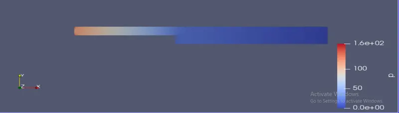
The pressure distribution when the grading factor is 1
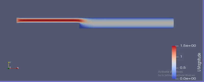
The velocity distribution when the grading factor is 1
Grading factor = (Size of the last cell)/(Size of the first cell)
When the grading factor is 0.2 the block mesh dict file is edited in the following way
 hex (0 1 2 3 11 12 13 14) (200 10 1) simpleGrading (0.2 1.2 1)
 hex (3 2 4 5 14 13 15 16) (200 10 1) simpleGrading (0.2 0.2 1)
 hex (1 8 7 2 12 19 18 13) (200 10 1) simpleGrading (1.2 1.2 1)
 hex (2 7 6 4 13 18 17 15) (200 10 1) simpleGrading (1.2 0.2 1)
 hex (10 9 8 1 21 20 19 12) (200 10 1) simpleGrading (1.2 1.2 1)
The pressure distribution at 0.2 grading factor
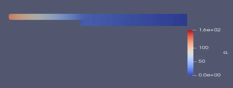
The velocity distribution at 0.2 grading factor
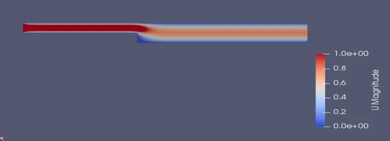
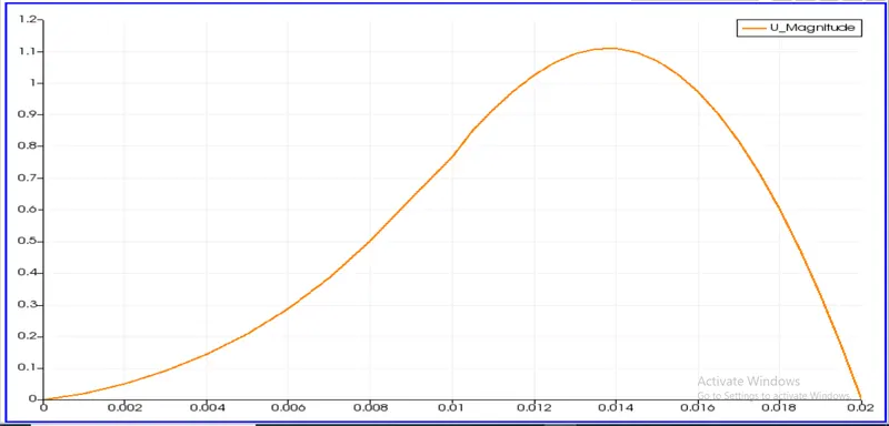
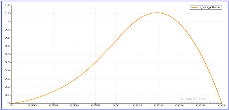
Now lets compare the velocity profiles at 0.085 m from inlet geometry at grading factor 1 and 0.2
The velocity profiles are plotted using plot over line tool in openfoam
The velocity profile at 0.085 m from inlet geometry when the grading factor is 1
The velocity profile at 0.085 m from inlet geometry when the grading factor is 0.2
Grading is the simple technique used for streching the mesh . Graded mesh helps us strech the mesh in one direction . In the complicated geometry the graded mesh helps us in getting the correct results in less amount of time . By limiting the number of elements required to solve we can gain the exact results using tge graded mesh .