Simulation of Backward Facing step using BlockMesh in OpenFOAM
# Objective:
The objective of this project to simulate the flow through the backwards-facing step using Incompressible, Laminar and Transient solver in OpenFoam.To study the effect of the grading factor of mesh on the velocity profile.
# Probelm Statement:
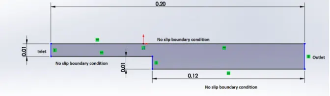
Create the above geometry using BlockMeshDict file available OpenFoam Tutorial.
The Number of cells in x-direction=200
The Number of cells in y-direcion=20
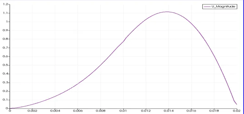
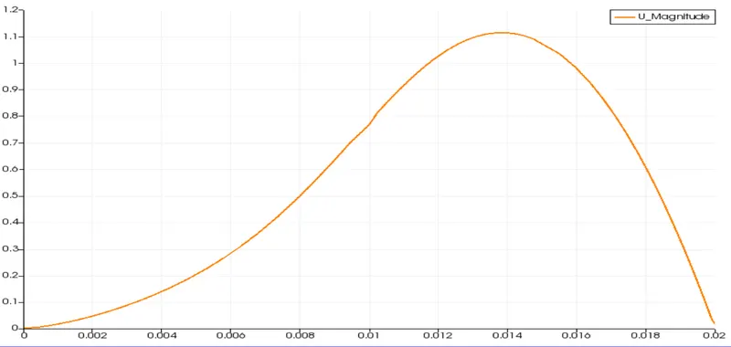
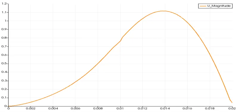
And the comparison of the velocity profile at 0.085 m from the inlet for different grid factor.
# Mesh Generation:
The above geometry can be divided into 5 blocks and giving the node number accordingly.
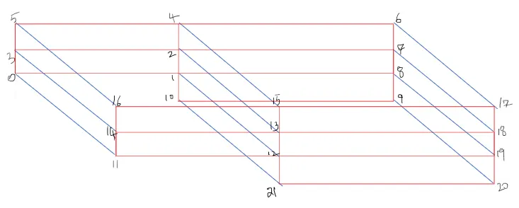
The geometry can be created using below-attached code (simple grading) of BlockMeshDict file. After editing the BlockMeshDict file blockMesh command is executed in the command window to get desired mesh generation in OpenFoam. After that to examine the mesh paraFoam command is used.
/*--------------------------------*- C++ -*----------------------------------*
  =========                 |
  \      /  F ield         | OpenFOAM: The Open Source CFD Toolbox
   \    /   O peration     | Website:  https://openfoam.org
    \  /    A nd           | Version:  8
     \/     M anipulation  |
*---------------------------------------------------------------------------*/
FoamFile
{
    version     2.0;
    format      ascii;
    class       dictionary;
    object      blockMeshDict;
}
// * * * * * * * * * * * * * * * * * * * * * * * * * * * * * * * * * * * * * //

convertToMeters 1;

vertices
(
    (0 0 0)
    (0.08 0 0)
    (0.08 0.005 0)
    (0 0.005 0)
    (0.08 0.01 0)
    (0 0.01 0)
    (0.20 0.01 0)
    (0.20 0.005 0)
    (0.20 0 0)
    (0.20 -0.01 0)
    (0.08 -0.01 0)
    (0 0 0.001)
    (0.08 0 0.001)
    (0.08 0.005 0.001)
    (0 0.005 0.001)
    (0.08 0.01 0.001)
    (0 0.01 0.001)
    (0.20 0.01 0.001)
    (0.20 0.005 0.001)
    (0.20 0 0.001)
    (0.20 -0.01 0.001)
    (0.08 -0.01 0.001)

);

blocks
(
    hex (0 1 2 3 11 12 13 14) (200 20 1) simpleGrading (1 1 1)
    hex (3 2 4 5 14 13 15 16) (200 20 1) simpleGrading (1 1 1)
    hex (2 7 6 4 13 18 17 15) (200 20 1) simpleGrading (1 1 1)
    hex (1 8 7 2 12 19 18 13) (200 20 1) simpleGrading (1 1 1)
    hex (10 9 8 1 21 20 19 12) (200 20 1) simpleGrading (1 1 1)
);

edges
(
);

boundary
(
    inlet
    {
        type patch;
        faces
        (
            (0 11 14 3)
            (3 14 16 5)
        );
    }
    outlet
    {
        type patch;
        faces
        (
            (9 8 19 20)
            (8 7 18 19)
            (7 6 17 18)
        );
    }
    frontAndBack
    {
        type empty;
        faces
        (
            (0 3 2 1)
            (3 5 4 2)
            (10 1 8 9)
            (2 1 7 8)
            (2 4 6 7)
            (11 12 13 14)
            (14 13 15 16)
            (21 20 19 12)
            (12 19 18 13)
            (13 18 17 15)
        );
    }
    NoSlipWalls
    {
      type wall;
      faces
      (
       (16 15 4 5)
       (15 17 6 4)
       (10 21 12 1)
       (0 1 12 11)
       (10 9 20 21)

      );
    }
);

mergePatchPairs
(
);

// ************************************************************************* //
# Boundary Conditions:
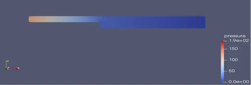
The exit pressure is atmospheric.
The inlet velocity is 1 m/s.
The Pressure and Velocity B.C code is edited as attached below.
# Pressure Boundary Condition:
/*--------------------------------*- C++ -*----------------------------------*
  =========                 |
  \      /  F ield         | OpenFOAM: The Open Source CFD Toolbox
   \    /   O peration     | Website:  https://openfoam.org
    \  /    A nd           | Version:  8
     \/     M anipulation  |
*---------------------------------------------------------------------------*/
FoamFile
{
    version     2.0;
    format      ascii;
    class       volScalarField;
    object      p;
}
// * * * * * * * * * * * * * * * * * * * * * * * * * * * * * * * * * * * * * //

dimensions      [0 2 -2 0 0 0 0];

internalField   uniform 0;

boundaryField
{
    inlet
    {
        type            zeroGradient;
    }

    outlet
    {
        type            fixedValue;
        value           uniform 0;
    }

    frontAndBack
    {
        type            empty;
    }
    NoSlipWalls
    {
        type            zeroGradient;
    }
}

// ************************************************************************* //
# Velocity Boundary Condition:
/*--------------------------------*- C++ -*----------------------------------*
  =========                 |
  \      /  F ield         | OpenFOAM: The Open Source CFD Toolbox
   \    /   O peration     | Website:  https://openfoam.org
    \  /    A nd           | Version:  8
     \/     M anipulation  |
*---------------------------------------------------------------------------*/
FoamFile
{
    version     2.0;
    format      ascii;
    class       volVectorField;
    object      U;
}
// * * * * * * * * * * * * * * * * * * * * * * * * * * * * * * * * * * * * * //

dimensions      [0 1 -1 0 0 0 0];

internalField   uniform (0 0 0);

boundaryField
{
    inlet
    {
        type            fixedValue;
        value           uniform (1 0 0);
    }

    outlet
    {
        type            zeroGradient;
    }

    frontAndBack
    {
        type            empty;
    }
   NoSlipWalls
    {
        type            noSlip;
    }
}

// ************************************************************************* //
# Selection of time Step size:
For the Transient Analysis, selection of Time step size plays an important role as it directly affects the stability of the solution.
Courant Number (CFL Number) should be less than 1 to get a stable solution for CFD Analysis.
for the above reason, Timestep size (dt) is selected as 0.00001.
This code can be edited in ControlDict file as attached below.
/*--------------------------------*- C++ -*----------------------------------*
  =========                 |
  \      /  F ield         | OpenFOAM: The Open Source CFD Toolbox
   \    /   O peration     | Website:  https://openfoam.org
    \  /    A nd           | Version:  8
     \/     M anipulation  |
*---------------------------------------------------------------------------*/
FoamFile
{
    version     2.0;
    format      ascii;
    class       dictionary;
    location    "system";
    object      controlDict;
}
// * * * * * * * * * * * * * * * * * * * * * * * * * * * * * * * * * * * * * //

application     icoFoam;

startFrom       startTime;

startTime       0;

stopAt          endTime;

endTime         0.5;

deltaT          0.00001;

writeControl    timeStep;

writeInterval   20;

purgeWrite      0;

writeFormat     ascii;

writePrecision  6;

writeCompression off;

timeFormat      general;

timePrecision   6;

runTimeModifiable true;


// ************************************************************************* //
# Selection of CFD Solver:
The CFD solver selection is done in such a way that it describes the physics of the flow problem. Flow conditions in this problem like
(1) Incompressible fluid
(2) Transient Analysis
(3) Laminar (Viscous) flow
(4) Newtonian Fluid
The physics of the problem can be solved using icoFoam Solver available in OpenFoam.
icoFoam Solver uses the PISO (Pressure Implicit with splitting of operators) algorithm to solve the continuity and Momentum equation (Navier Stokes Equations).
/*---------------------------------------------------------------------------*
  =========                 |
  \      /  F ield         | OpenFOAM: The Open Source CFD Toolbox
   \    /   O peration     | Website:  https://openfoam.org
    \  /    A nd           | Copyright (C) 2011-2018 OpenFOAM Foundation
     \/     M anipulation  |
-------------------------------------------------------------------------------

Application
    icoFoam

Description
    Transient solver for incompressible, laminar flow of Newtonian fluids.

*---------------------------------------------------------------------------*/

#include "fvCFD.H"
#include "pisoControl.H"

// * * * * * * * * * * * * * * * * * * * * * * * * * * * * * * * * * * * * * //

int main(int argc, char *argv[])
{
    #include "setRootCaseLists.H"
    #include "createTime.H"
    #include "createMesh.H"

    pisoControl piso(mesh);

    #include "createFields.H"
    #include "initContinuityErrs.H"

    // * * * * * * * * * * * * * * * * * * * * * * * * * * * * * * * * * * * //

    Info<< "nStarting time loopn" << endl;

    while (runTime.loop())
    {
        Info<< "Time = " << runTime.timeName() << nl << endl;

        #include "CourantNo.H"

        // Momentum predictor

        fvVectorMatrix UEqn
        (
            fvm::ddt(U)
          + fvm::div(phi, U)
          - fvm::laplacian(nu, U)
        );

        if (piso.momentumPredictor())
        {
            solve(UEqn == -fvc::grad(p));
        }

        // --- PISO loop
        while (piso.correct())
        {
            volScalarField rAU(1.0/UEqn.A());
            volVectorField HbyA(constrainHbyA(rAU*UEqn.H(), U, p));
            surfaceScalarField phiHbyA
            (
                "phiHbyA",
                fvc::flux(HbyA)
              + fvc::interpolate(rAU)*fvc::ddtCorr(U, phi)
            );

            adjustPhi(phiHbyA, U, p);

            // Update the pressure BCs to ensure flux consistency
            constrainPressure(p, U, phiHbyA, rAU);

            // Non-orthogonal pressure corrector loop
            while (piso.correctNonOrthogonal())
            {
                // Pressure corrector

                fvScalarMatrix pEqn
                (
                    fvm::laplacian(rAU, p) == fvc::div(phiHbyA)
                );

                pEqn.setReference(pRefCell, pRefValue);

                pEqn.solve();

                if (piso.finalNonOrthogonalIter())
                {
                    phi = phiHbyA - pEqn.flux();
                }
            }

            #include "continuityErrs.H"

            U = HbyA - rAU*fvc::grad(p);
            U.correctBoundaryConditions();
        }

        runTime.write();

        Info<< "ExecutionTime = " << runTime.elapsedCpuTime() << " s"
            << "  ClockTime = " << runTime.elapsedClockTime() << " s"
            << nl << endl;
    }

    Info<< "Endn" << endl;

    return 0;
}


// ************************************************************************* //
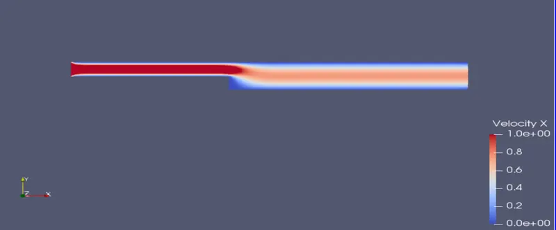
# Grading Factor 1
# Mesh:
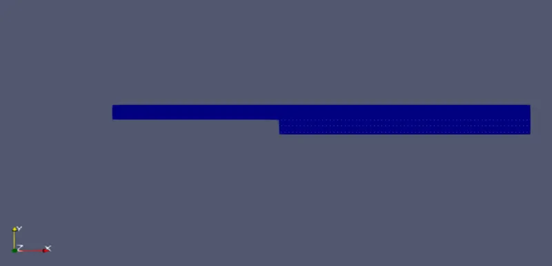
Mesh Generation using simple grading scheme with grading factor 1.
# Pressure:
# Velocity:
Velocity Profile:
Variation of velocity at 0.085 m from the inlet.
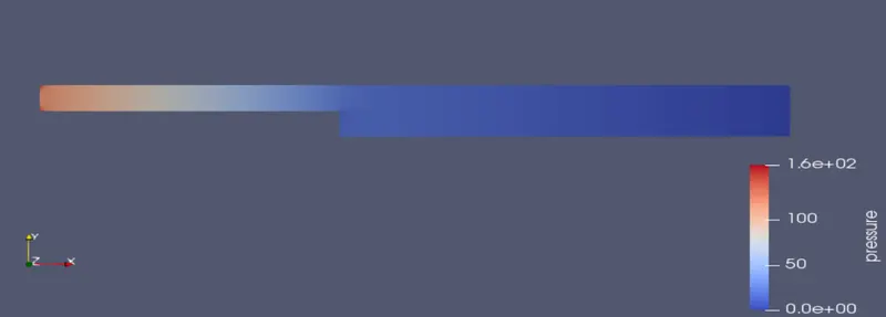
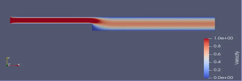
# Grading Factor 0.2:
To change the grading factor to 0.2 from the default value, the following changes can be made in BlockMeshDict file.
blocks
(
    hex (0 1 2 3 11 12 13 14) (200 20 1) simpleGrading (0.2 1.2 1)
    hex (3 2 4 5 14 13 15 16) (200 20 1) simpleGrading (0.2 0.2 1)
    hex (2 7 6 4 13 18 17 15) (200 20 1) simpleGrading (1.2 0.2 1)
    hex (1 8 7 2 12 19 18 13) (200 20 1) simpleGrading (1.2 1.2 1)
    hex (10 9 8 1 21 20 19 12) (200 20 1) simpleGrading (1.2 1.2 1)
);
# Pressure:
# Velocity:
# Velocity Profile:
Variation of velocity at 0.085 m from the inlet.
Grading Factor 0.8:
To change the grading factor to 0.8 from the default value, the following changes can be made in BlockMeshDict file.
blocks
(
    hex (0 1 2 3 11 12 13 14) (200 20 1) simpleGrading (0.8 1.8 1)
    hex (3 2 4 5 14 13 15 16) (200 20 1) simpleGrading (0.8 0.8 1)
    hex (2 7 6 4 13 18 17 15) (200 20 1) simpleGrading (1.8 0.8 1)
    hex (1 8 7 2 12 19 18 13) (200 20 1) simpleGrading (1.8 1.8 1)
    hex (10 9 8 1 21 20 19 12) (200 20 1) simpleGrading (1.8 1.8 1)
);
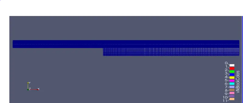
# Mesh:
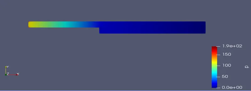
# Pressure:
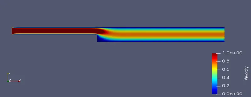
# Velocity:
#Velocity Profile:
Variation of velocity at 0.085 m from the inlet.
# Conclusions:
- As the Mesh size getting finer and finer, the output result will be more accurate.
- Overall all meshing schemes gives the same result but region at which accurate velocity profile needs to be found out, a finer mesh is used.
- For Grading factor 0.2, it will give the finer result and accurate velocity curve as compared to other grading factors.