Week 8 - BlockMesh Drill down challenge
AIM :
To simulate the flow through a backward facing step using the icoFoam solver in OpenFOAM software and to study the effect of mesh grading factor on the velocity and pressure magnitude profile.
THEORY :
Mesh Specifications:
- Number of cells along the x direction (longer dimension) = 200
- Number of cells along the longer y direction = 20
Boundary condition specification :
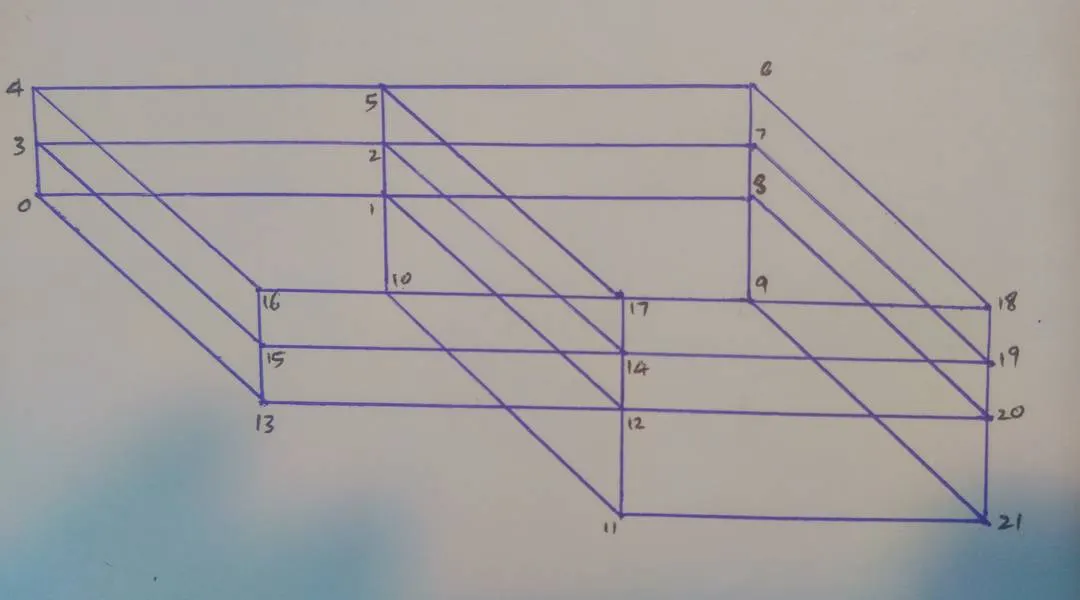
Block:
Simulation Steps:
- Open the terminal in Linux Operating system.
- The 'tutorial' folder in OpenFoam folder is opened(type 'cd $FOAM_TUTORIALS') and (use 'ls' i.e list to view the contents inthe tutorials)the 'incompressible' directory is opened(type 'cd incompressible').
- Then the 'cavity' is selected and opened, inside of which there exists another 'cavity' folder.
- This 'cavity' folder is copied into 'run' folder and renamed as 'cavity_test'.Command used is 'cp -r cavity/ $FOAM_RUN/cavity_test'. Never run your simulation directly in the tutorial file itself. It may corrupt the entire tutorial file if any mistakes or errors took. To regain those files, we need to uninstall the software and install again which is a long-process.
- Later on we navigate into 'solver' folder, inside of which there exists an 'incompressible' directory (similar to that in 'tutorials')
- There is a solver called 'icoFoam' inside the 'incompressible'. This is the solver we are supposed to use for this simulation.Open the files using the change directory 'cd' command.
- Now we go to the 'run' folder, and open the 'cavity_test' directory.
- There will be 'p' and 'U' inside '0' folder. The 'p' directory stands for pressure and it needs to be edited in gedit as per our requirements. The 'U' directory stands for Velocity and it also needs to be edited in gedit as per our requirements.
- Next the System directory is selected from directory 'cavity_test', inside of which there exists 'blockMeshDict' , 'controlDict', 'fvSchemes', 'fvSolutions'.
- The 'fvSchemes' and 'fvSolutions' are methods and need not be edited
- The 'blockMeshDict' has to be edited according to our part design.
- The 'controlDict' also has to be edited according to our part design ,while selecting the 'delta t' value, be aware of the courant number. It should be less than one (< 1). Otherwise, the solution may diverge and stopped forcibly by software itself.
- Next, we type in 'blockMesh' command to initiate the mesh.
- After completing it we need to check the mesh that it has any error in it or not. For that, 'checkMesh' command is used.
- Then the solver which we have referred to earlier is typed in as 'icoFoam'. The result is obtained. To get a graphical view type in 'paraFoam'.
- Do this for the grading factors 0.2, 1.
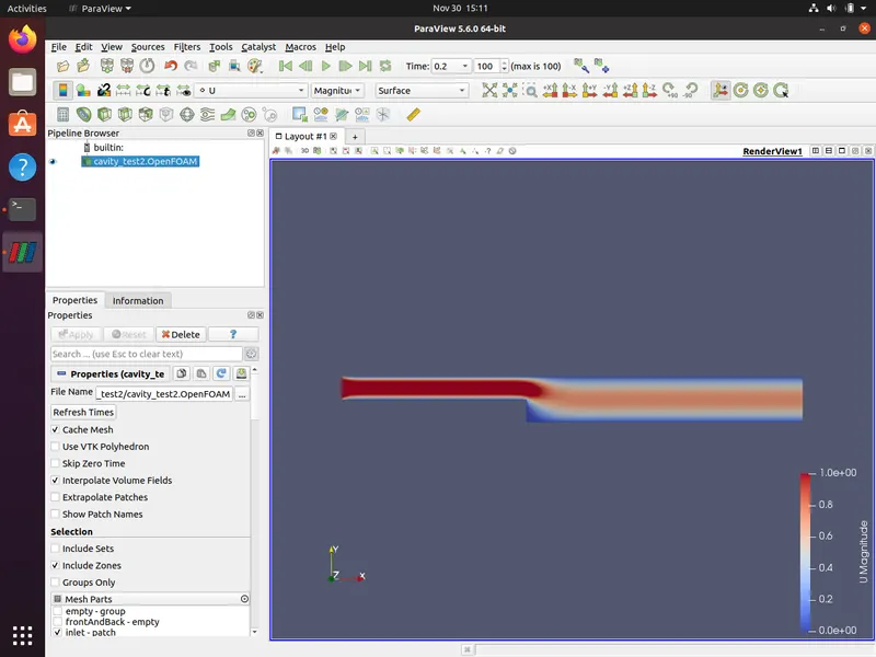
- Then we compare velocity magnitude contours near the step region for the mesh grading factor of 0.2, 1.
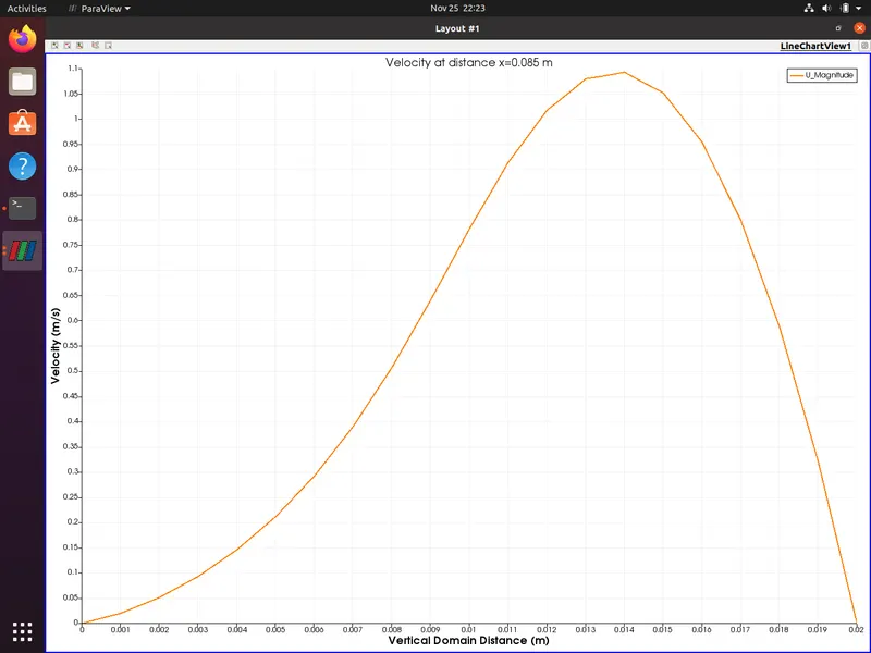
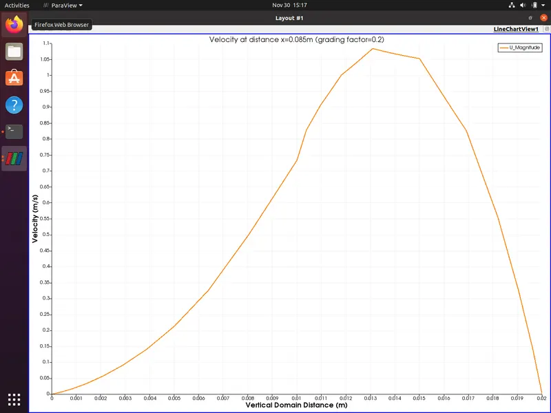
- Measure the velocity profile at 0.085 m from the inlet of the geometry.
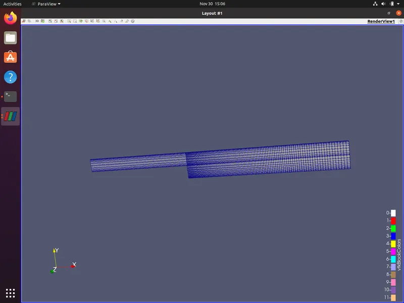
The top wall consisting of faces (16 17 5 4), (17 18 6 5), the bottom wall consisting of faces (0 1 12 13), (10 9 21 11) and the left step face (1 10 11 12) are considered no-slip walls and the grading factor is to be applied near these walls. The front and back faces are not considered and denoted by empty as this is a 2D simulation, these values are provided inside the BlockMeshDict file.
BlockMeshDict file:
/*--------------------------------*- C++ -*----------------------------------*\
  =========                 |
  \\      /  F ield         | OpenFOAM: The Open Source CFD Toolbox
   \\    /   O peration     | Website:  https://openfoam.org
    \\  /    A nd           | Version:  8
     \\/     M anipulation  |
\*---------------------------------------------------------------------------*/
FoamFile
{
    version     2.0;
    format      ascii;
    class       dictionary;
    object      blockMeshDict;
}
// * * * * * * * * * * * * * * * * * * * * * * * * * * * * * * * * * * * * * //

convertToMeters 0.01;

vertices
(
    (0 0 0)     //vertex no.0
    (8 0 0)     //vertex no.1
    (8 0.5 0)   //vertex no.2
    (0 0.5 0)   //vertex no.3
    (0 1 0)     //vertex no.4
    (8 1 0)     //vertex no.5
    (20 1 0)    //vertex no.6
    (20 0.5 0)  //vertex no.7
    (20 0 0)    //vertex no.8
    (20 -1 0)   //vertex no.9
    (8 -1 0)    //vertex no.10
    (8 -1 0.1)  //vertex no.11
    (8 0 0.1)   //vertex no.12
    (0 0 0.1)   //vertex no.13
    (8 0.5 0.1) //vertex no.14
    (0 0.5 0.1) //vertex no.15
    (0 1 0.1)   //vertex no.16
    (8 1 0.1)   //vertex no.17
    (20 1 0.1)  //vertex no.18
    (20 0.5 0.1)//vertex no.19
    (20 0 0.1)  //vertex no.20
    (20 -1 0.1) //vertex no.21
);

blocks
(
    hex (0 1 2 3 13 12 14 15) (80 5 1) simpleGrading (1 5 1)
    hex (3 2 5 4 15 14 17 16) (80 5 1) simpleGrading (1 0.2 1)
    hex (1 8 7 2 12 20 19 14) (120 5 1) simpleGrading (5 5 1)
    hex (2 7 6 5 14 19 18 17) (120 5 1) simpleGrading (5 0.2 1)
    hex (10 9 8 1 11 21 20 12) (120 10 1) simpleGrading (5 5 1)
);

edges
(
);

boundary
(
    inlet
    {
        type patch;
        faces
        (
            (0 13 15 3)
            (3 15 16 4)
        );
    }
    outlet
    {
        type patch;
        faces
        (
            (8 7 19 20)
            (7 6 18 19)
            (9 8 20 21)
        );
    }
    noSlipWalls
    {
        type wall;
        faces
        (
            (0 1 12 13)
            (10 9 21 11)
            (16 17 5 4)
            (17 18 6 5)
            (1 10 11 12)
        );
    }
    frontAndBack
    {
        type empty;
        faces
        (
            (13 12 14 15)
            (15 14 17 16)
            (12 20 19 14)
            (14 19 18 17)
            (11 21 20 12)
            (0 3 2 1)
            (3 4 5 2)
            (1 2 7 8)
            (2 5 6 7)
            (10 1 8 9)
        );
    }
);

mergePatchPairs
(
);

// ************************************************************************* //
Timestep:
The time control information is provided inside the 'controlDict' file inside the system folder. For this case, the time-step size is chosen such that the Courant number remains well below 1 throughout the geometry. The value for time-step size is given 1e-4 and simulation time is given 0.2s
controlDict file:
/*--------------------------------*- C++ -*----------------------------------*\
  =========                 |
  \\      /  F ield         | OpenFOAM: The Open Source CFD Toolbox
   \\    /   O peration     | Website:  https://openfoam.org
    \\  /    A nd           | Version:  8
     \\/     M anipulation  |
\*---------------------------------------------------------------------------*/
FoamFile
{
    version     2.0;
    format      ascii;
    class       dictionary;
    location    "system";
    object      controlDict;
}
// * * * * * * * * * * * * * * * * * * * * * * * * * * * * * * * * * * * * * //

application     icoFoam;

startFrom       startTime;

startTime       0;

stopAt          endTime;

endTime         0.2;

deltaT          0.0001;

writeControl    timeStep;

writeInterval   20;

purgeWrite      0;

writeFormat     ascii;

writePrecision  6;

writeCompression off;

timeFormat      general;

timePrecision   6;

runTimeModifiable true;


// ************************************************************************* //
The value of the velocity at inlet is given 1m/s and the value for pressure is given 0 Pa.
Velocity Boundary Conditions file:
/*--------------------------------*- C++ -*----------------------------------*\
  =========                 |
  \\      /  F ield         | OpenFOAM: The Open Source CFD Toolbox
   \\    /   O peration     | Website:  https://openfoam.org
    \\  /    A nd           | Version:  8
     \\/     M anipulation  |
\*---------------------------------------------------------------------------*/
FoamFile
{
    version     2.0;
    format      ascii;
    class       volVectorField;
    object      U;
}
// * * * * * * * * * * * * * * * * * * * * * * * * * * * * * * * * * * * * * //

dimensions      [0 1 -1 0 0 0 0];

internalField   uniform (0 0 0);

boundaryField
{
    inlet
    {
        type            fixedValue;
        value           uniform (1 0 0);
    }
    outlet
    {
        type            zeroGradient;
    }

    noSlipWalls
    {
        type            noSlip;
    }

    frontAndBack
    {
        type            empty;
    }
}

// ************************************************************************* //
Pressure Boundary Conditions file:
/*--------------------------------*- C++ -*----------------------------------*\
  =========                 |
  \\      /  F ield         | OpenFOAM: The Open Source CFD Toolbox
   \\    /   O peration     | Website:  https://openfoam.org
    \\  /    A nd           | Version:  8
     \\/     M anipulation  |
\*---------------------------------------------------------------------------*/
FoamFile
{
    version     2.0;
    format      ascii;
    class       volScalarField;
    object      p;
}
// * * * * * * * * * * * * * * * * * * * * * * * * * * * * * * * * * * * * * //

dimensions      [0 2 -2 0 0 0 0];

internalField   uniform 0;

boundaryField
{
    inlet
    {
        type            zeroGradient;
    }

    outlet
    {
        type           fixedValue;
        value          uniform 0;
    }

    noSlipWalls
    {
        type            zeroGradient;
    }

    frontAndBack
    {
        type            empty;
    }
}

// ************************************************************************* //
Result:
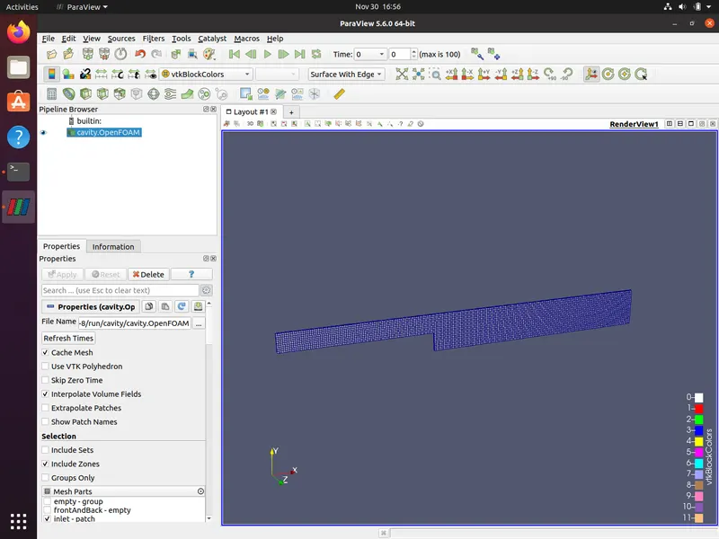
Mesh geometry for Grading Factor =1
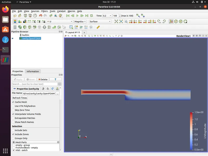
Velocity contour (for GF=1)
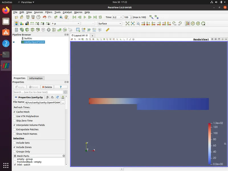
Pressure contour (for GF=1)
Velocity magnitude profile (GF=1)
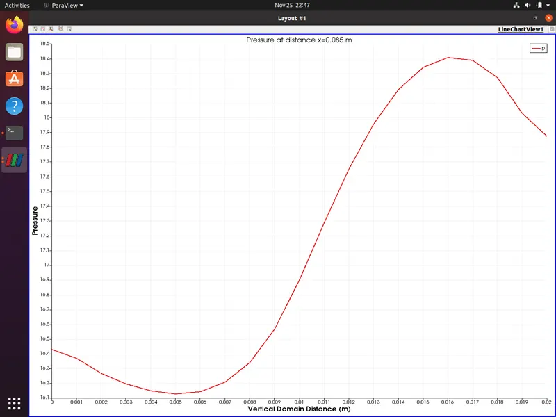
Pressure magnitude profile (GF=1)
Mesh geometry for Grading Factor =0.2
Velocity contour (for GF=0.2)
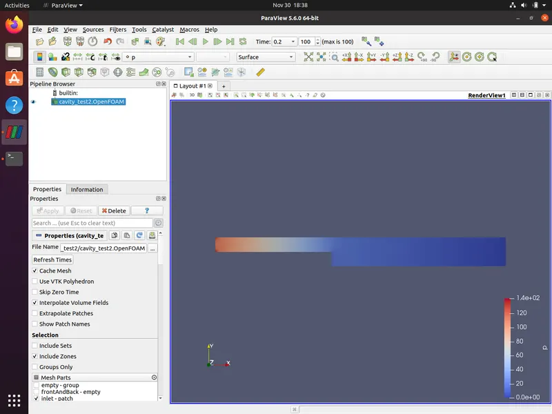
Pressure contour (for GF=1)
Velocity magnitude profile (GF=0.2)
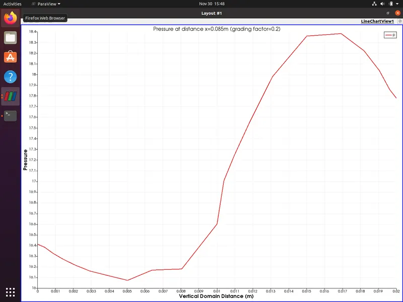
Pressure magnitude profile (GF=0.2)
INFERENCE:
We can infer that for velocity profiles of mesh with higher grading factors(GF=1) appear to be smoother than the one with lower grading factor(GF=0.2). This is because a mesh with a lower grading factor depicts more accurate results.
Therefore with grading, we are able to refine the mesh in key regions without increasing the number of grid points or cells inside a block. This implies that, for the same number of cells, we can manipulate the mesh size at the desired region to get a more accurate result.