Week 8 - BlockMesh Drill down challenge
Aim: To simulate an incompressible-laminar-viscous flow through the backward facing step geometry using icoFoam solver of OpenFOAM software.
Theory:
Following geometry is considered.
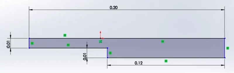
Figure: Model used for simulation
For creation of geometry and meshing, model is devided into blocks as shown below.

Also, indexing is done to create gemetry and mesh as shown below.
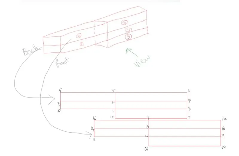
Geometry and Mesh specification:
/*--------------------------------*- C++ -*----------------------------------*\
  =========                 |
  \\      /  F ield         | OpenFOAM: The Open Source CFD Toolbox
   \\    /   O peration     | Website:  https://openfoam.org
    \\  /    A nd           | Version:  7
     \\/     M anipulation  |
\*---------------------------------------------------------------------------*/
FoamFile
{
    version     2.0;
    format      ascii;
    class       dictionary;
    object      blockMeshDict;
}
// * * * * * * * * * * * * * * * * * * * * * * * * * * * * * * * * * * * * * //

convertToMeters 0.01;

vertices
(
    (0 0 0)   // vertex 0
    (8 0 0)   // vertex 1
    (8 0.5 0) // vertex 2
    (0 0.5 0) // vertex 3
    (8 1 0) // vertex 4
    (0 1 0) // vertex 5
    (20 1 0) // vertex 6
    (20 0.5 0) // vertex 7
    (20 0 0) // vertex 8
    (20 -1 0) // vertex 9
    (8 -1 0) // vertex 10
    (0 0 0.1)   // vertex 11
    (8 0 0.1)   // vertex 12
    (8 0.5 0.1) // vertex 13
    (0 0.5 0.1) // vertex 14
    (8 1 0.1) // vertex 15
    (0 1 0.1) // vertex 16
    (20 1 0.1) // vertex 17
    (20 0.5 0.1) // vertex 18
    (20 0 0.1)  // vertex 19
    (20 -1 0.1) // vertex 20
    (8 -1 0.1) // vertex 21
);

blocks
(
    hex (0 1 2 3 11 12 13 14) (100 20 1) simpleGrading (1 1 1) //block 0
    hex (3 2 4 5 14 13 15 16) (100 20 1) simpleGrading (1 1 1) //block 1
    hex (1 8 7 2 12 19 18 13) (100 20 1) simpleGrading (1 1 1) //block 2
    hex (2 7 6 4 13 18 17 15) (100 20 1) simpleGrading (1 1 1) //block 3
    hex (10 9 8 1 21 20 19 12) (100 20 1) simpleGrading (1 1 1) //block 4
);

edges
(
);

boundary
(
    inlet
    {
        type patch;
        faces
        (
            (0 11 14 3)
            (3 14 16 5)
        );
    }
    outlet
    {
        type patch;
        faces
        (
            (8 7 18 19)
            (9 8 19 20)
            (7 6 17 18)
        );
    }
    walls
    {
        type wall;
        faces
        (
            (4 5 16 15)
            (6 4 15 17)
            (1 10 21 12)
            (0 1 12 11)
            (10 9 20 21)
        );
    }

);

mergePatchPairs
(
);

// ************************************************************************* //
Specifications of boundary conditions
/*--------------------------------*- C++ -*----------------------------------*\
  =========                 |
  \\      /  F ield         | OpenFOAM: The Open Source CFD Toolbox
   \\    /   O peration     | Website:  https://openfoam.org
    \\  /    A nd           | Version:  7
     \\/     M anipulation  |
\*---------------------------------------------------------------------------*/
FoamFile
{
    version     2.0;
    format      ascii;
    class       volScalarField;
    object      p;
}
// * * * * * * * * * * * * * * * * * * * * * * * * * * * * * * * * * * * * * //

dimensions      [0 2 -2 0 0 0 0];

internalField   uniform 0;

boundaryField
{
    inlet
    {
        type            zeroGradient;  //Neumann
    }

    outlet
    {
        type            fixedValue;
        value           uniform 0;
    }

    walls
    {
        type            zeroGradient; //Neumann
    }
}

// ************************************************************************* //
/*--------------------------------*- C++ -*----------------------------------*\
  =========                 |
  \\      /  F ield         | OpenFOAM: The Open Source CFD Toolbox
   \\    /   O peration     | Website:  https://openfoam.org
    \\  /    A nd           | Version:  7
     \\/     M anipulation  |
\*---------------------------------------------------------------------------*/
FoamFile
{
    version     2.0;
    format      ascii;
    class       volVectorField;
    object      U;
}
// * * * * * * * * * * * * * * * * * * * * * * * * * * * * * * * * * * * * * //

dimensions      [0 1 -1 0 0 0 0];

internalField   uniform (0.01 0 0);

boundaryField
{
    inlet
    {
        type            fixedValue;
        value           uniform (0.01 0 0); //Dirichlet
    }

    outlet
    {
        type            zeroGradient;  //Neumann
    }

    walls
    {
        type           noSlip;
    }
}

// ************************************************************************* //
Specification of simulation time and time step size
/*--------------------------------*- C++ -*----------------------------------*\
  =========                 |
  \\      /  F ield         | OpenFOAM: The Open Source CFD Toolbox
   \\    /   O peration     | Website:  https://openfoam.org
    \\  /    A nd           | Version:  7
     \\/     M anipulation  |
\*---------------------------------------------------------------------------*/
FoamFile
{
    version     2.0;
    format      ascii;
    class       dictionary;
    location    "system";
    object      controlDict;
}
// * * * * * * * * * * * * * * * * * * * * * * * * * * * * * * * * * * * * * //

application     icoFoam;

startFrom       startTime;

startTime       0;

stopAt          endTime;

endTime         0.5;

deltaT          1e-4;

writeControl    timeStep;

writeInterval   20;

purgeWrite      0;

writeFormat     ascii;

writePrecision  6;

writeCompression off;

timeFormat      general;

timePrecision   6;

runTimeModifiable true;


// ************************************************************************* //
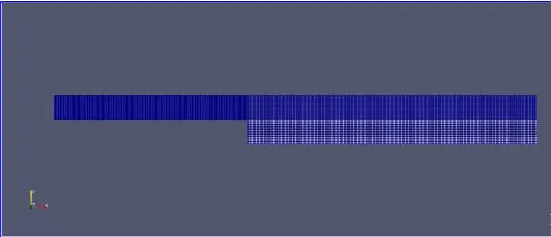
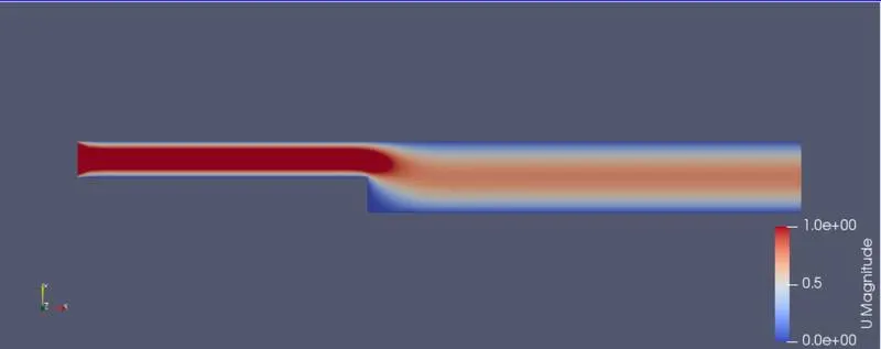
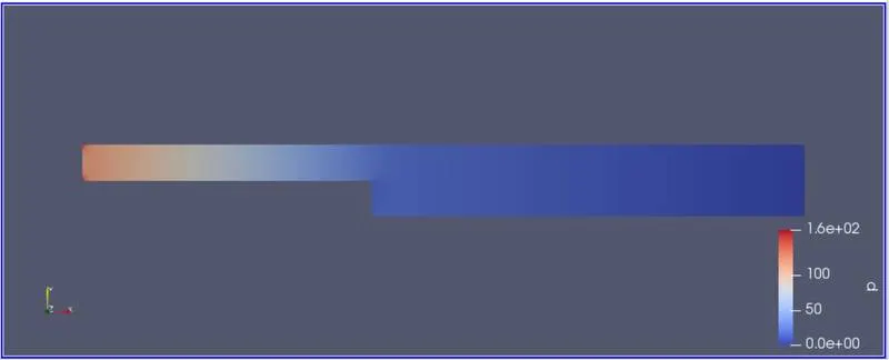
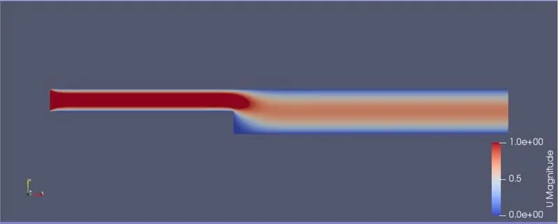
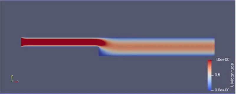
Mesh, pressure and velocity variation is shown below with any mesh grading. Simulation time is taken as 0.5 seconds.
Velocity variation
pressure variation
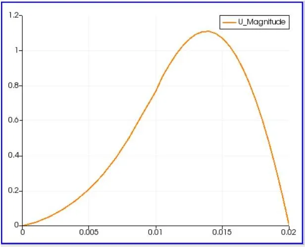
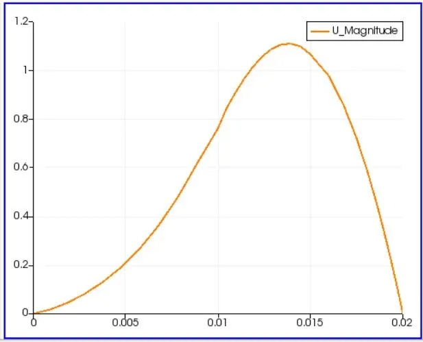
Velocity profile at a distance from 0.085 m neat step from inlet is shown beow
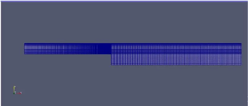
Now same results are shown below for grading factor of 0.2. Few changes are done in code as shown below.
blocks
(
    hex (0 1 2 3 11 12 13 14) (200 10 1) simpleGrading (0.2 1.2 1)
    hex (3 2 4 5 14 13 15 16) (200 10 1) simpleGrading (0.2 0.2 1)
    hex (2 7 6 4 13 18 17 15) (200 10 1) simpleGrading (1.2 1.2 1)
    hex (1 8 7 2 12 19 18 13) (200 10 1) simpleGrading (1.2 0.2 1)
    hex (10 9 8 1 21 20 19 12) (200 10 1) simpleGrading (1.2 1.2 1)
);
Mesh
Velocity variation
pressure variation
Velocity profile at a distance from 0.085 m neat step from inlet is shown beow
Conclusion:
With and without grading factor, velocity plot is same with neglisible variations. For finer mesh with grading factor results can be visualise in more better way to capture boundary physics.