Week 8-3D Tetra Meshing Challenge
AIM: to create 3d tetra meshing on given three components.
- Create a Teramesh for Housing component with the following quality criteria.
TetraMesh Generation Method: 2D to 3D Conversion
Elements sizes: Min- 2 Units, Target- 5 Units, Max- 7 Units
Tet collapse: 0.15
it has two components
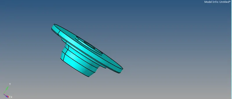
component 1
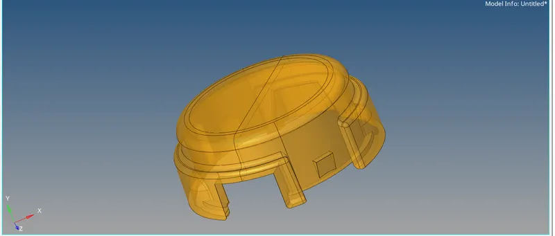
component 2
- For the given model, Create a 3D Tetramesh with the following quality criteria.
TetraMesh Generation Method: Quick Tetra Mesh/ Volume Tetra Mesh
Target Element size: 3 Units.
Tet Collapse: 0.15
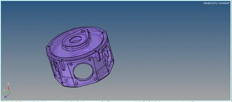
model 2
- For the given assembly model, Create a 3D Tetramesh with the following quality criteria.
TetraMesh Generation Method: Quick Tetra Mesh/ Volume Tetra Mesh
Target Element size: 4 Units.
Tet Collapse: 0.15
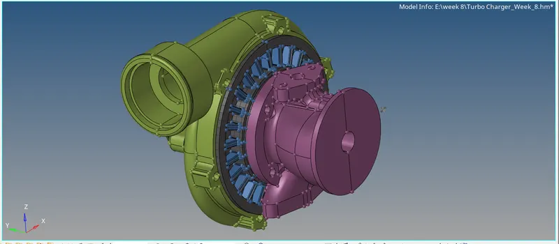
turbocharger (model 3)
1 housing component:
this component is used to cover the inner parts of the assembly.
procedure:
because of having a thickness of more than 6mm we should mesh the component with 3d elements.
to create mesh we should create it by using the tetra mesh option where first we need to create 2d on the surfaces of components and then convert it into 3D.
geometry clean
Geom-quick edit panel-toggling edges /replacing points/surface trim with lines.
1. import the model into the hyper mesh and then check for the geometrical errors by putting it into topo mode.in geometry clean up we toggled edges to avoid minimum element size error.
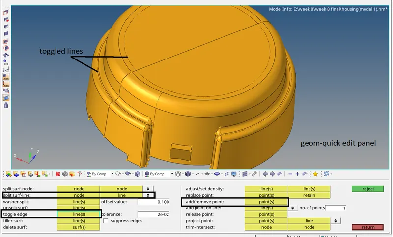
geometry clean up
2d mesh creation
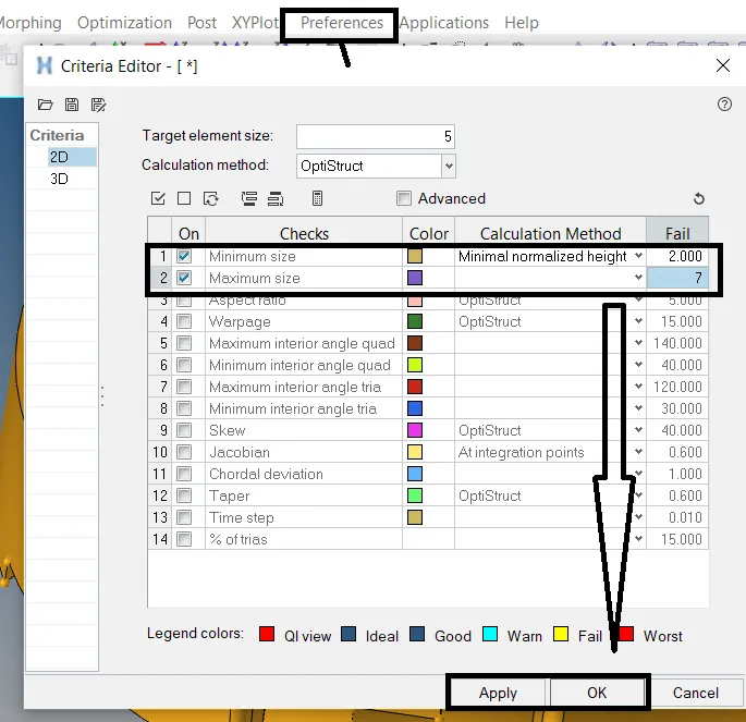
set criteria file with minimum element size as 2 and maximum element size as 7
preferences-criteria file setting-set element sie and above parameters.
2Dpanel-auto mesh-select the surfaces-set element size to 5 and change mesh type to tetra because it's easy to create a mesh with tetra but to get accurate and more precise analysis output we should go for Hexa meshing which is difficult to mesh complex designs.
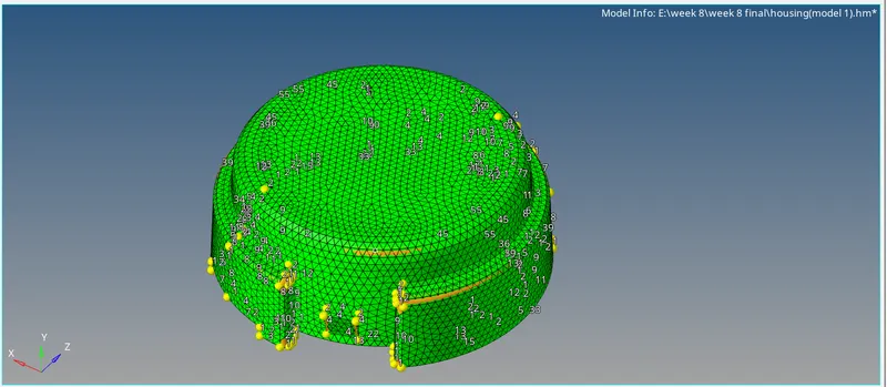
2d meshing on surface
we should do a quality check on elements created for minimum and maximum element size
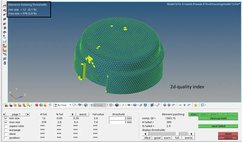
quality check
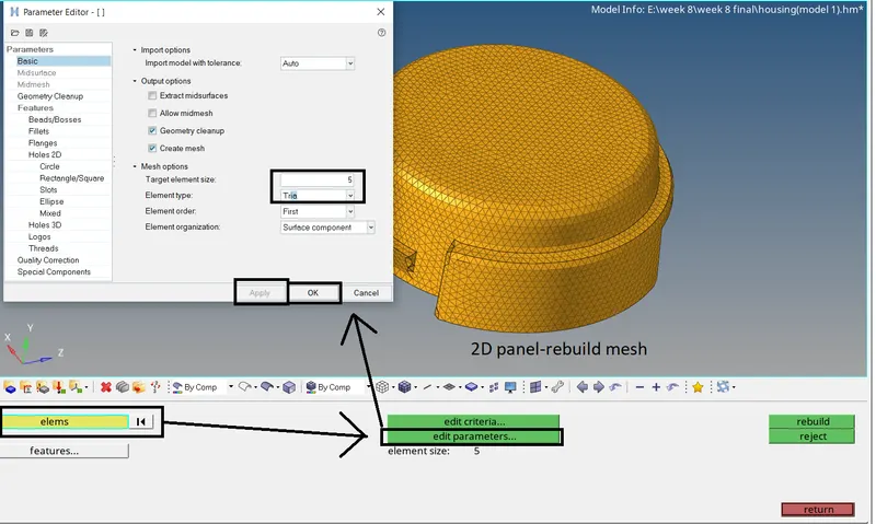
the above figure shows our elements failed to overcome this by using the rebuild mesh option .while using the rebuild option set element criteria as follows
2Dpanel- rebuild mesh-select elements-edit parameter(set element size and mesh type as tria)-apply-ok.
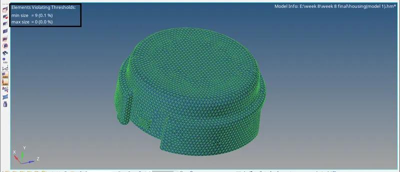
above figure after rebuild option quality gets improved.
but still, we have 9 elements failed for minimum element size this can be set by clean-up tools(element optimisation/place nodes) in the quality index
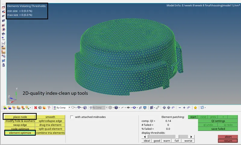
2Dquality check ok
converting 2D to 3D
go for 3D panel-tetra mesh-tetra mesh parameters for better results

to convert 2d mesh to 3d by choosing option tetra mesh-select elements infixed trias/quads to tetra mesh-check the checkboxes.
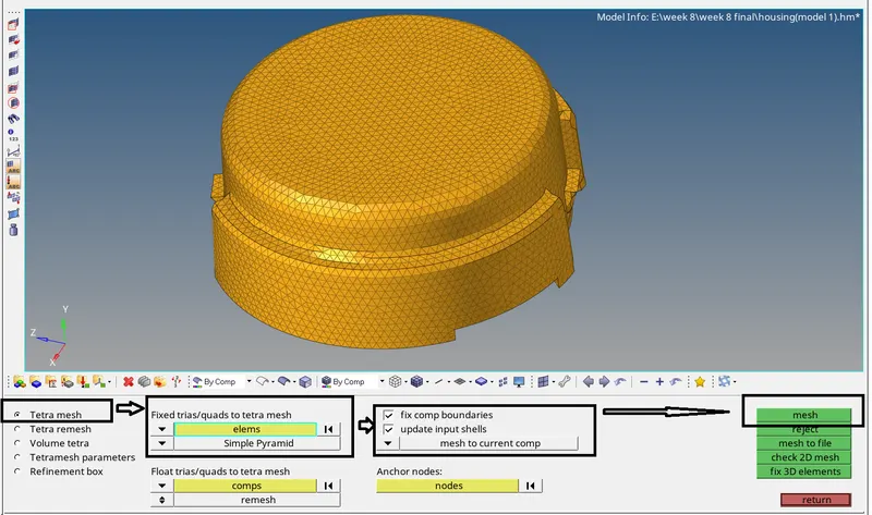
2d to 3d conversion option setting
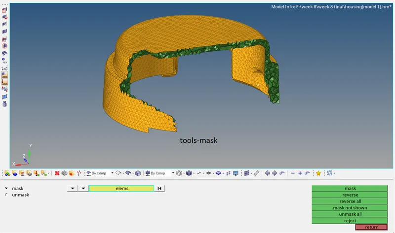
check for 3d elements are created or not
this can be done by masking some elements
tool-mask-select elements-mask
check for tet collapse
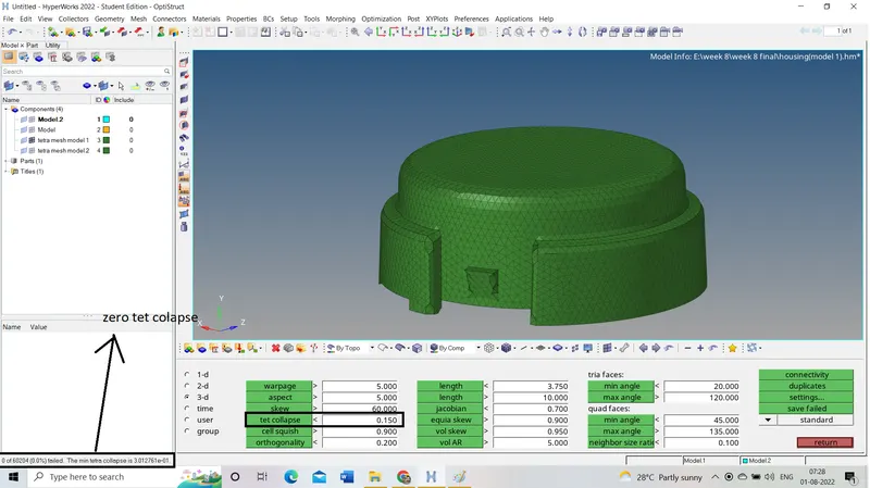
tet collapse:
it is the quality criteria of tetra elements tet collapse can be defined as the height of the node from the opposite face. to clear tet collapse error, we should maintain the height value between the minimum element size and the maximum element size.
These errors can be cleared in two methods
1. manual method.
using options like replace nodes, translate and distance options helps more
2. tetra re-mesh.
by re-meshing, the tetras shot out the problem easily (but it will not work all time)
tools-check elements -change criteria to 3D - update tet collapse values-click on it to check for errors.
component 2 :
the second component consists of solids delete the solids by using the delete option
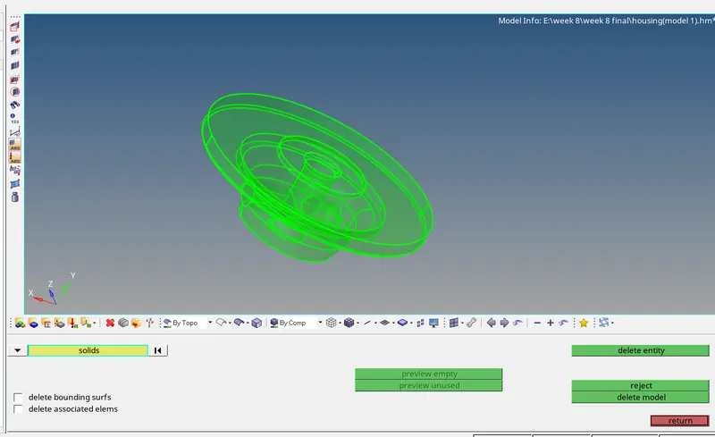
solid component
f2-select solids option to sect solids-delete.
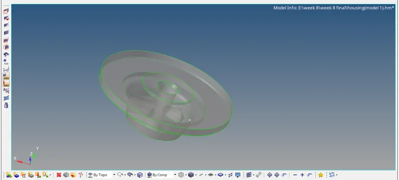
surfaces
2D-auto mesh-select elements-set element size-auto mesh
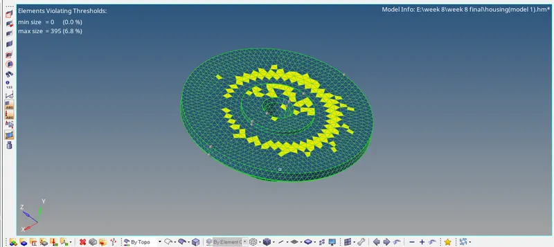
2d mesh
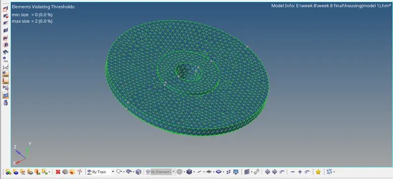
rebuild mesh
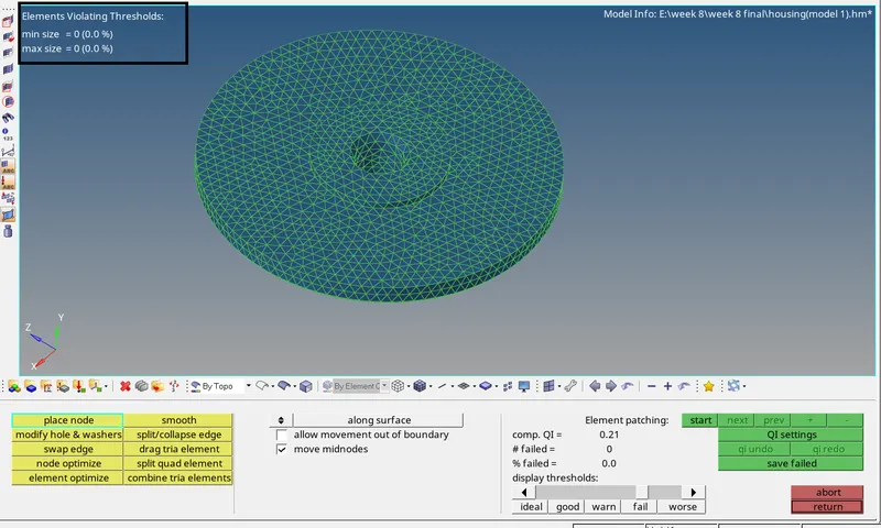
final quality check
conversion of 2D to 3D mesh
3D-tetra mesh-tetra parameters(set max, min and tet collapse values)
then 3d- tetra mesh-tetra mesh-select elements in fixed tria/quads for tetra mesh option(selecting elements in this option creates 3d elements making a connection with 2d elements so we can avoid errors in mesh flow and tet collapse errors.) -check in two boxes-mesh.
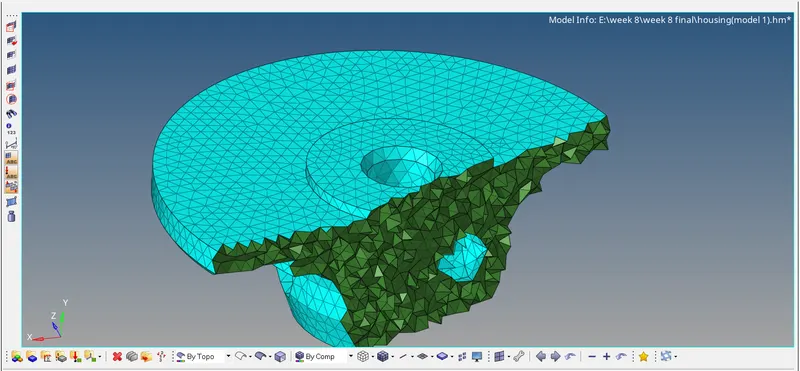
3d elements
after the creation of 3D elements, we should check for tet collapse
tools-check elements -change criteria to 3D - update tet collapse values-click on it to check for errors.
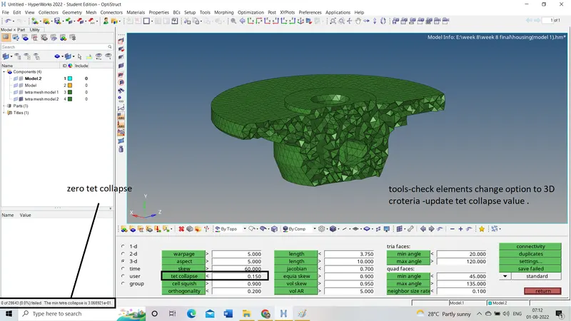
checking tet collapse
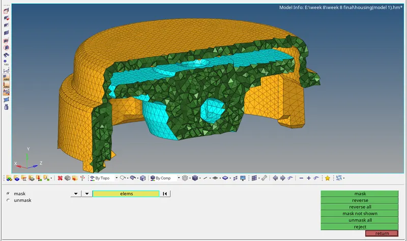
3D tetra mesh from 2D mesh
2. model 2
model 2
as model 2 is supposed to mesh in 3d by using volume tetra/quick tetra taking target element size as 3 units and tet collapse is 0.15.
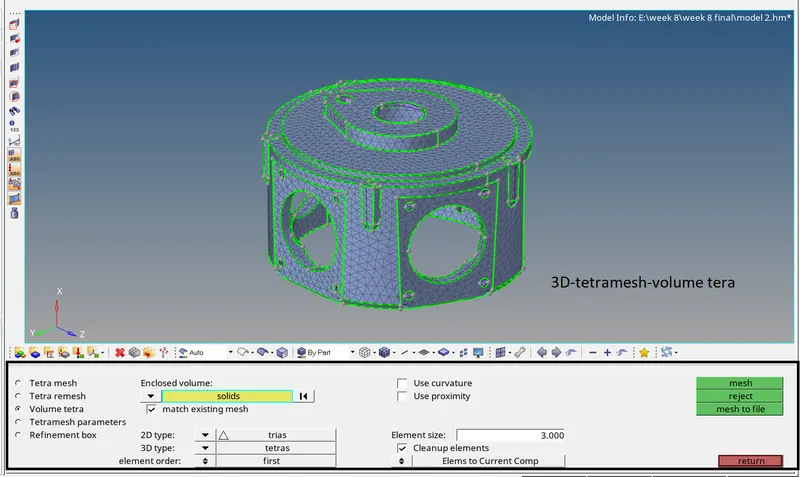
here we are using the volume tetra option to create a mesh.
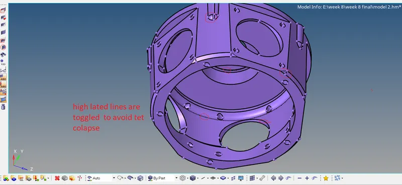
geometry clean up
in this we defeature some camphor regions by replacing the points(Geom-quick edit panel).and toggling the feature lines forming sharp edges and unnecessary lines.
generation of 3D mesh
3Dpanel - tetra mesh-go to tetra parameters(set values)-change option to volume tetra -select solids- set 2D type as TRIA -3D TYPE AS TETRA mesh -set element size to 3 units-mesh.
checking for tet collapse
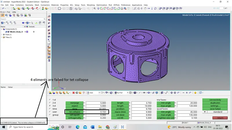
These 4 elements failed for tet collapse .save these failed elements by clicking save failed.
and mask them by retrieving options so we can have control over elements to edit.
tools-mask-click on elements-select the elements by retrieve option- mask-reverse.the result will be following
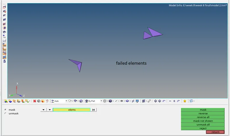
these are cleared by replacing nodes by using replace option (2D panel-replace) after check-in the distance between the nodes (Geom-distance-select between two nodes)
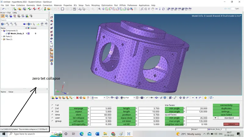
3D quality check
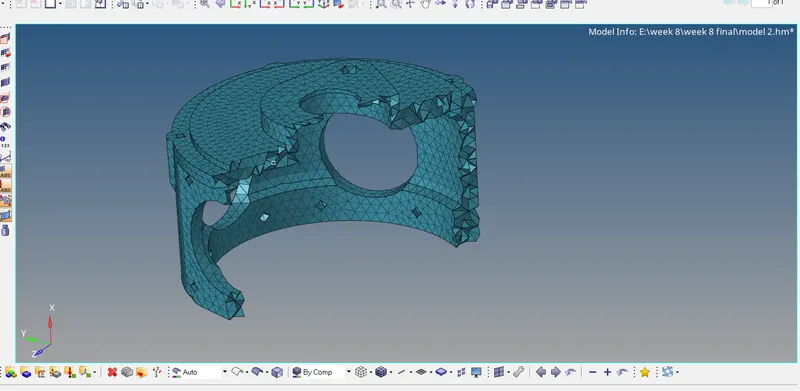
model 2(3D mesh)
3. turbocharger (model 3)
turbochargers are mostly used in automobiles running with internal combustion engines
in this model, we have 4 components
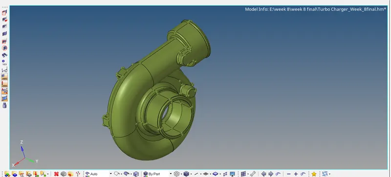
1. casing
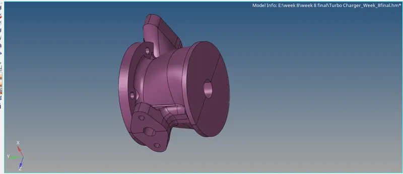
2. hub
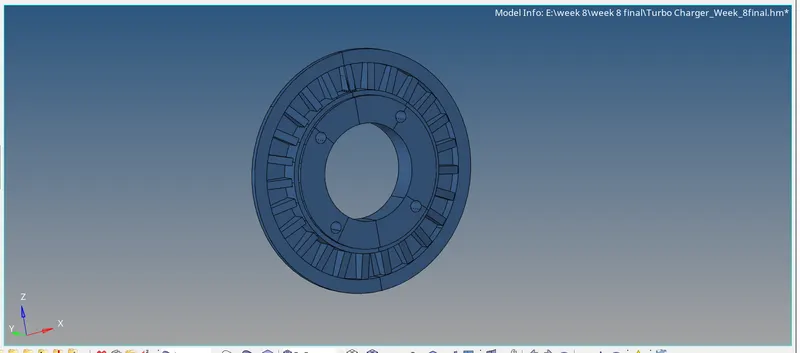
3. supporting plate
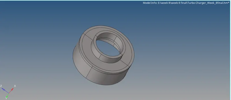
4. holder- housing
casing :
these are surface components
our task is to create a mesh by using volume tetra /quick tetra mesh on the component.
note :
The quick tetra option is not working on this component and shows some surface errors that are need to be manually cleared.
go for volume tetra mesh while selecting surfaces it selects half of the component and is allowed to mesh the half portion only and tried for many ways to solve this by cleaning geometry.
geometry clean-up:
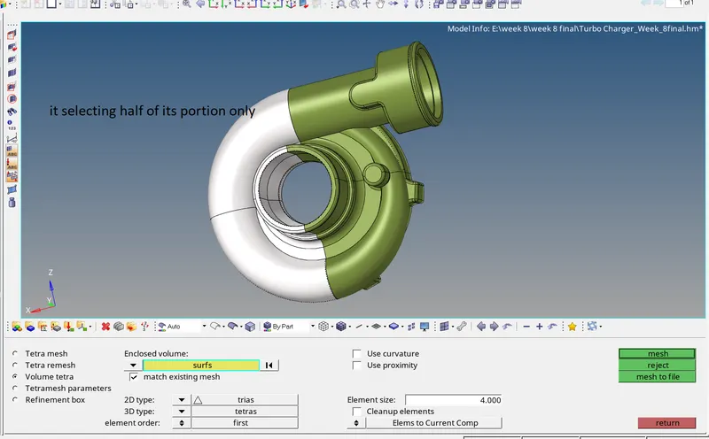
error: it should not be selected the component as shown above
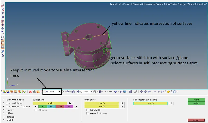
this can be cleared by deleting the surface and parting out the component for that first we need to find the intersecting surface by selecting the self-intersection option.
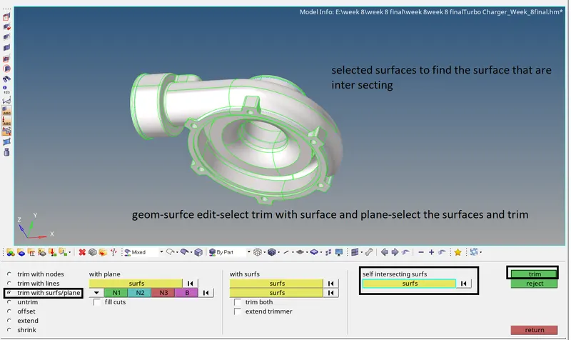
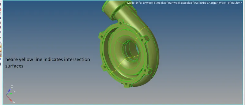
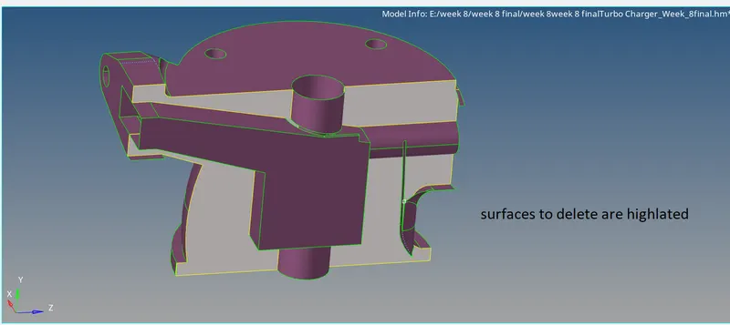
in the above figure, yellow lines indicate surfaces that are intersecting .these can be deleted by masking the component in half.
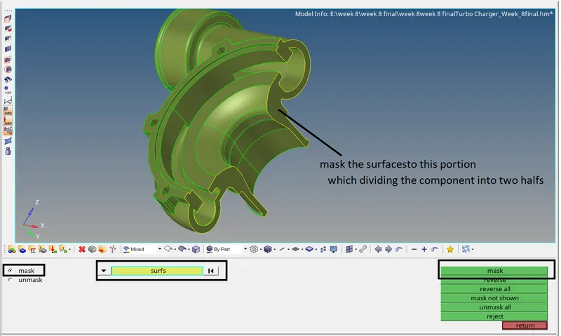
delete the surfaces as follows
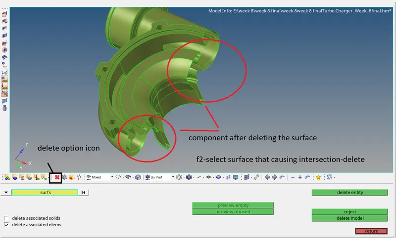
then toggle the surfaces having a probability of creating teat collapse.
3d mesh
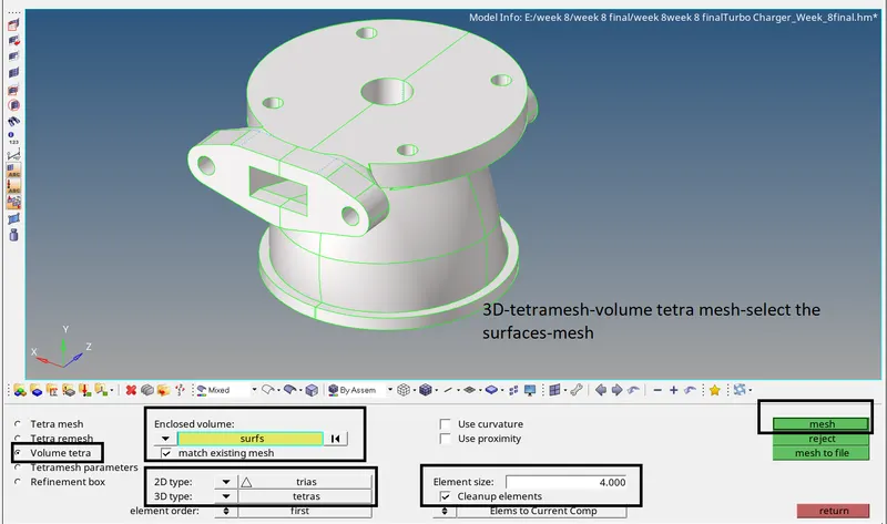
set tetra parameters as follows

creating volume tetra mesh
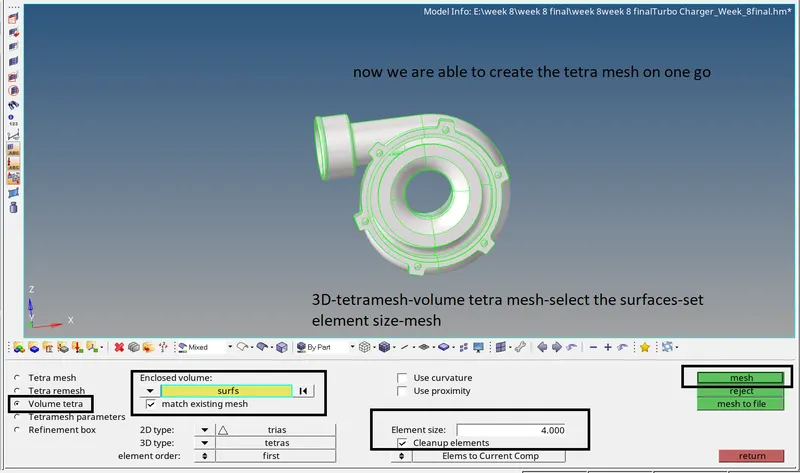
volume tetra mesh
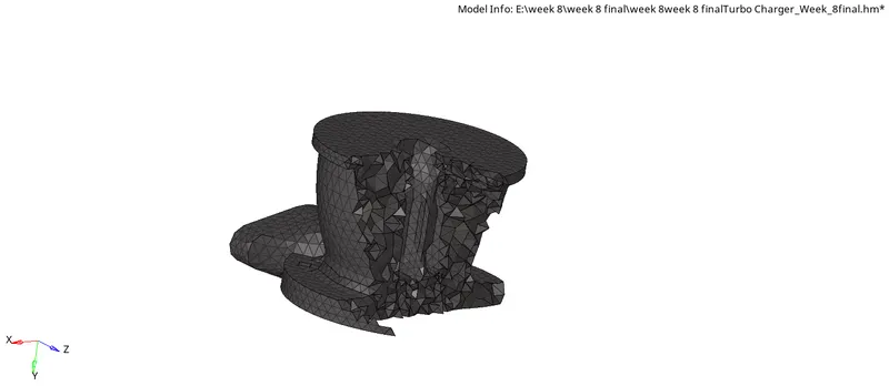
check for 3d elements
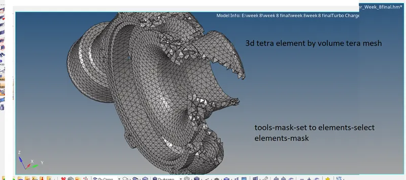
check for tet collapse
tools-check elements-tet collapse
save the failed elements
then mask and reverse it to isolate failed elements.
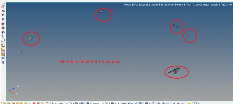
elements failed for tet collapse
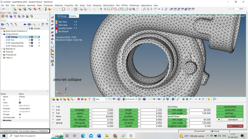
tet collapse is cleared
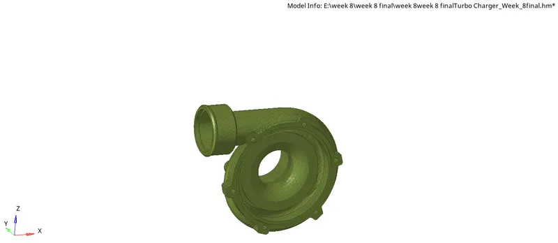
result
hub:
geometry clean up
Geom-quick edit-toggle edge
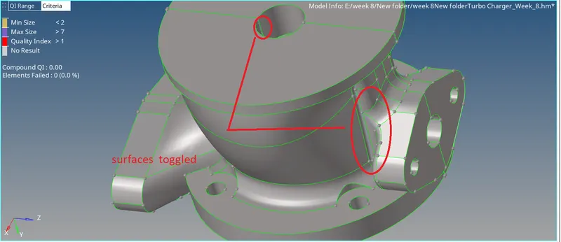
surface clean up
the hub also has the same surface casing this is also solved in the same way.
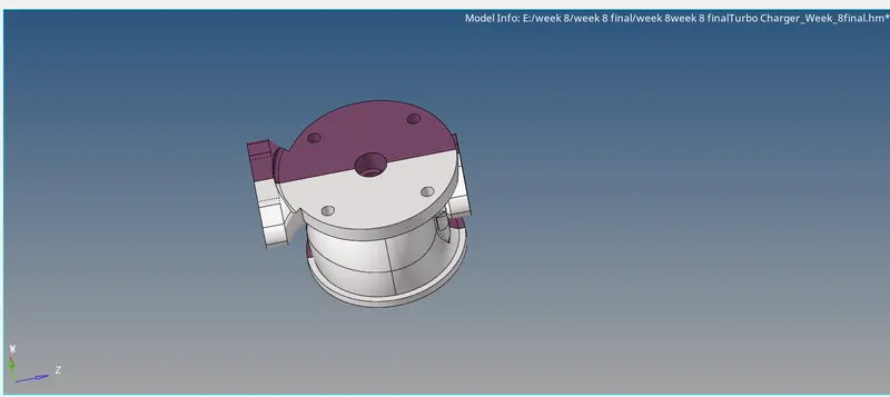
error
tetra mesh creation by volume tetra option:
checking the creation of the elements
check for tet collapse:
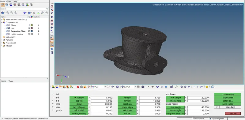
elements failed for tet collapse are 7
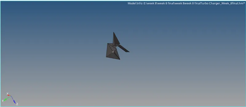
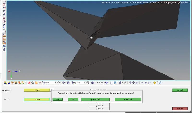
these can be clear by replacing the points
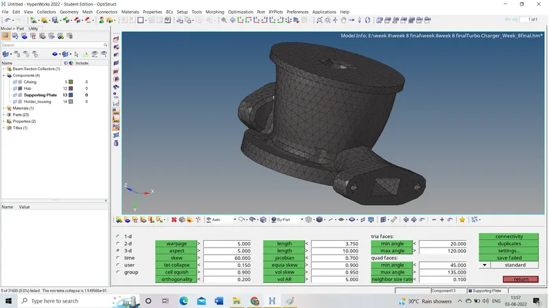
zero tet collapse
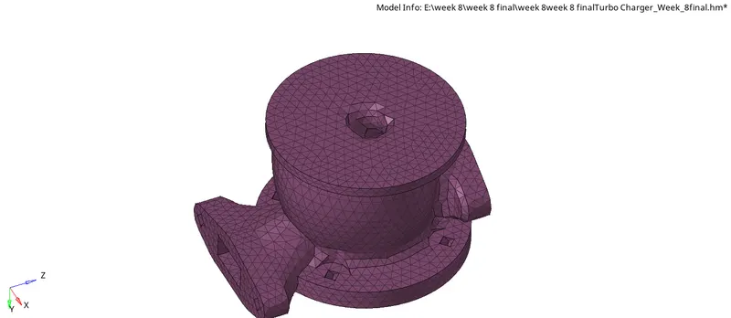
result
supporting plate:
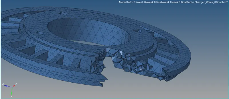
this one also faces the same surface errors while creating a mesh it causing the below-shown connectivity errors in the mesh part.
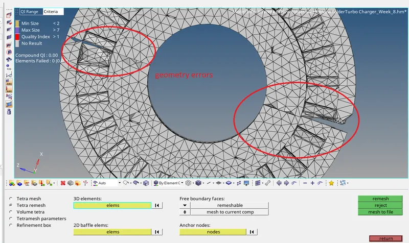
element connection error
geometry clean-up:
this error can be solved by deleting the surfaces by following the process followed for the above two components.
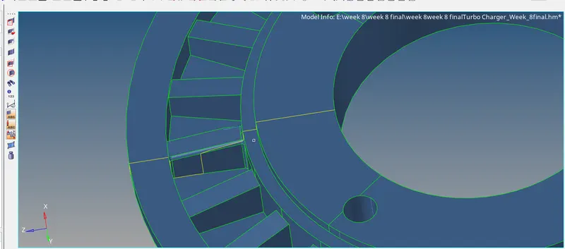
self-intersection surface
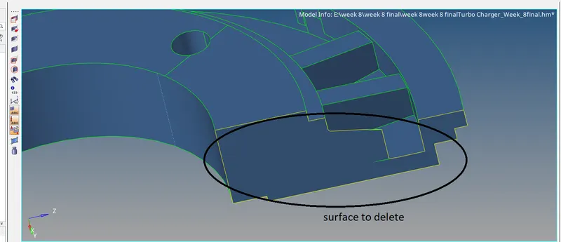
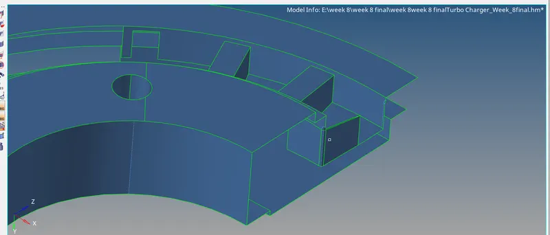
the result after deleting the surface
creation of 3d tetra mesh:
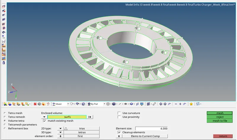
result
check for tet collapse:
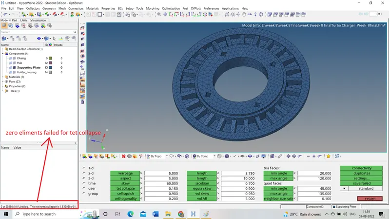
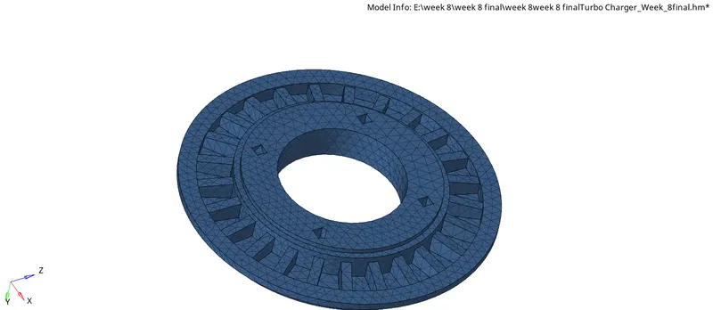
result
holder housing:
in this component, we face the same surface problem and also be solved as the above ones
quick tetra mesh:
this is the second method to create tetra mesh directly
View-browser-hypermesh-utility-Geom/mesh-in mesh tools select quick tetra
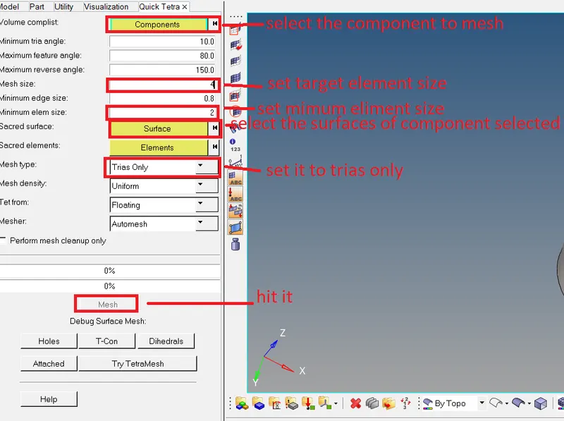
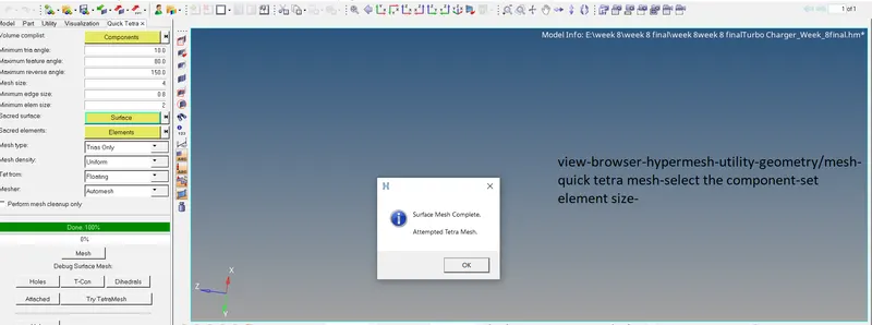
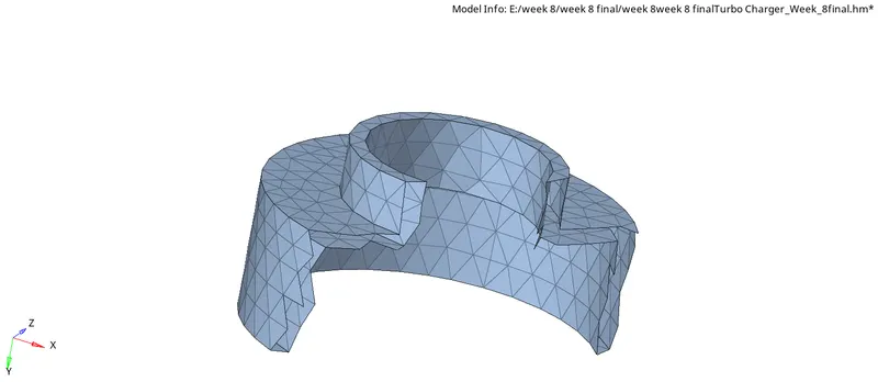
2d mesh created by quick tetra mesh
it shows quick tetra mesh created surface mesh and attending to create 3d tetra mesh.
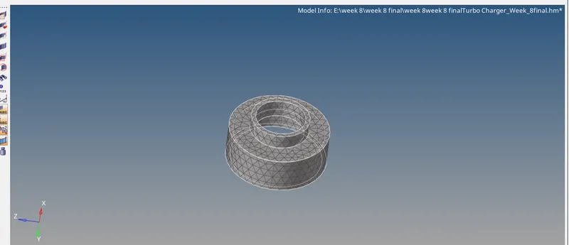
quick tetra mesh
quick tetra mesh create a mesh in separate component as quick tetra as shown below
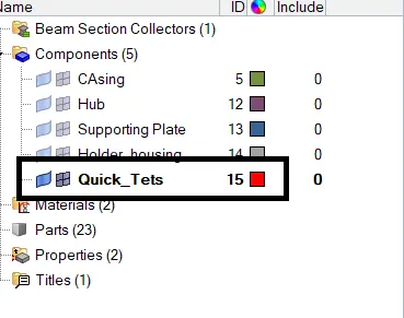
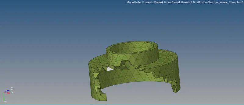
check for 3d elements created
for visualisation colour of the component is changed
quality check:

elements failed for tet collapse
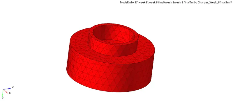
result
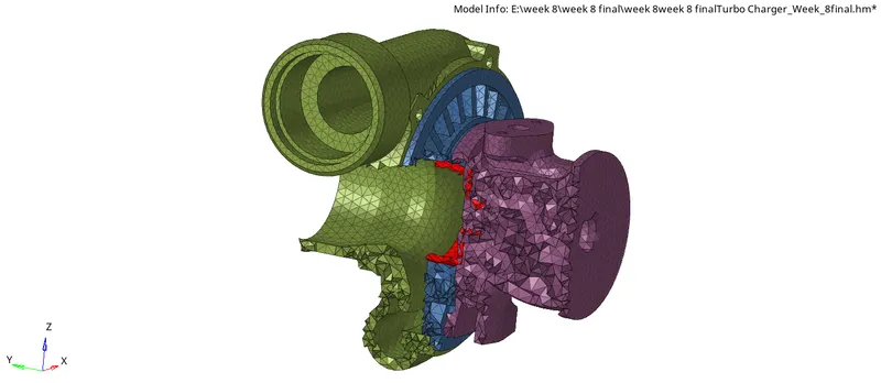
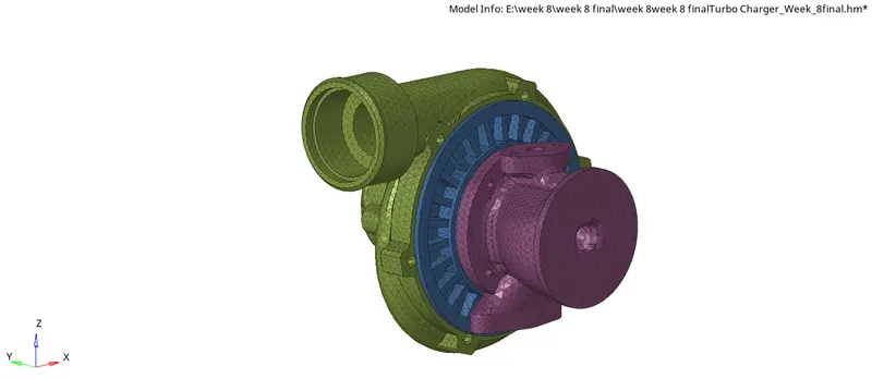
model 3
conclusion:
while creating mesh three steps to follow
A.geometry cleanup
B.creating mesh can be possible in different ways as follow
1. from 2d to 3d using tetra mesh
2. direct 3d by
a.void tetra mesh
b. quick tetra mesh
C. quality check
1. if the mesh is created by the first method we should check 2d elements for minimum and maximum failure and also check 3d elements for tet collapse failure.
2. if the mesh is created directly then it's enough to check for tet collapse.
D. clearing the failure elements
1. manual method by using options like replace points/translate/distance/edit element
2. tetra remesh
the end