Week 8:- 3D Finishing - Challenges 1
1.) What do you understand by the 3D finish process?
This is the final stage where the design process is completed and getting freezed (no modification in design after this). Then it is ready for final simulation to check for flaws and feasibility and 2D detailing.
2.) What are the points need to be taken care of while finishing the design?
- Hole concentricity and sizes: All the holes of mating part in the fixture should be checked for hole concentricity.
- Avoiding clash between different parts: Standard gap should be maintained to avoid clash between different parts.
- Pneumatic Layouting: pneumatic layouting is collection of different pneumatic pipes which works as a inlet to the pneumatic cylinder. It should be done properly for proper functioning of the units.
- Proper renaming of parts or assemblies as per the standards:It is done in the design tree consists of lot & lot of parts which ease in identification and modification of parts.
- Follow the hole colouring standard: It should be done as per the customer requirements.
- Machining area: The area should be defined and identified using standard colour code.
- Mylar splitting as per panel profile: The mating face of both rest and clamp mylar should be spilited along with the shape of work piece.
3.) What are rough Locators & what is their use?
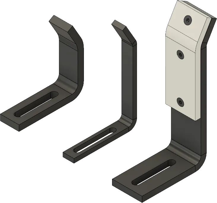
- Rough locators are used to position or locate the workpiece on the fixture pin in the automation process.
- The accuracy in the location of workpiece defines the quality of the final product.
- It is a fool protfing method because it positions the part/workpiece with respect to the angle of respective panel.
4.) What are the points you need to consider while designing a rough locator?
- The pin top must be above 10 to 15 mm from the top surface of workpiece at the particular location.
- The tip of rough locator is designed with a particular entry angle it ranges between 30 t 45 degree which eases the entry of workpiece.
- Rough locator has to be placed in the same angle of the car part edge with a minimum distance of 2-5 mm from the edge of the car part.
- The rough locator must have slot in the direction of car panel guiding.
- The rough locator should guiding the panel before 10 to 15 mm to the start of pin engagement.
5.) What is the gun study process?
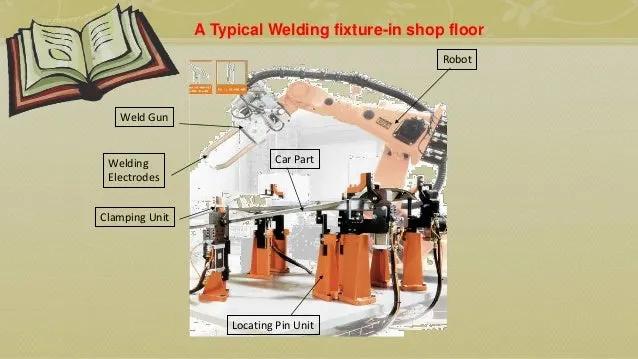
- It is the process of checking feasibility of whether the gun is able to weld at the car panels selected weld spot point.
- The below images shows the weld gun doing spot welding and the weld location where the spot is created on the car panel.
- Gun study is necessary as the BIW fixture design.
- In 3D software gun study is done by actually introducing welding gun in fixture that we have designed, at all the individual points by placing the electrode using constrain option and check for clash between gun assembly and car panel or some other components in fixture.
- If the clash occurs between any of the component, rectify it by adjusting the shape or size or orientation of the parts.
- According to that units are designed so that there's no problem while welding process.
6.) What are the points need to consider during the gun study?
- The weld electrode axis must be perpendicular to the surface of the workpiece.
- Check for standard clearance between gun assembly and parts while at welding and movement from one weld point to other point.
- It ensure that the gun should not colloid or clash with any of the component in the assembly.
- The number of weld spots and the time required for welding at each spot shows the total time required for spot welding.
- Robot cycle time is calculated while doing proper gun study.
- Collision checking is done on simulation software to check whether the welding process is done without ant collision with any units in fixture.
7.) What is pneumatic routing?
Pneumatic systems should be efficient and leak free. Sometimes, they are not, because of improper tube line routing which resulted due to either lack of knowledge, or corners cut on planning time, or both.
Planning tube line routing is a time investment, but it can have a big ROI, especially for complex systems. During system design, routing should be developed as the next step after sizing the tube lines and selecting the appropriate fittings.
There are some guidelines provided for routing as shown below
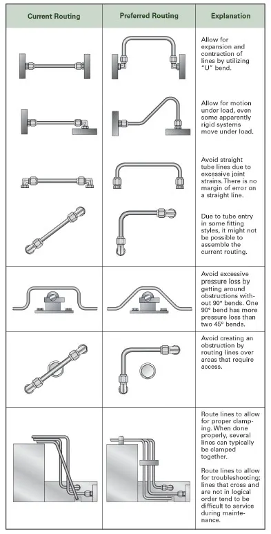
- Leave fitting joints as accessible as possible. Inaccessible joints are difficult and time-consuming to assemble, tighten and service.
- Use software tools to make labor-intensive calculations such as pressure drop.
- Employ U-bends to allow for line contraction and expansion.
- Include offset bends to allow for motion under load, regardless of how ‘rigid’ the system seems.
- Favor bends rather than straight tube lines, because a straight line tube assembly with no bends, like the example of the test stand mentioned above, can cause joint stain, which may lead to leaking.
- Make sure routing design allows room for assembly of any connections required.
- Minimize pressure drop by getting around obstructions with as few 90° bends as possible. One 90° bend has more pressure loss than two 45° bends.
- Route lines around rather than over areas that require regular access or maintenance.
- Design routing with clamping in mind. Appropriate design leads logically to proper clamping. Often, it’s possible to clamp several lines together.
- Keep troubleshooting and maintenance in mind: focus on logical design and avoid crossed lines.
- Design the tube line routing to reduce likelihood of users standing or climbing on plumbing
8.) What is the solenoid valve?
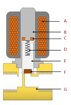
A solenoid valve is an electrically controlled valve. The valve features a solenoid, which is an electric coil with a movable ferromagnetic core (plunger) in its center. In the rest position, the plunger closes off a small orifice. An electric current through the coil creates a magnetic field. The magnetic field exerts an upwards force on the plunger opening the orifice. This is the basic principle that is used to open and close solenoid valves.
A solenoid valve consists of two main components: a solenoid and a valve body (G). Figure 2 shows the components. A solenoid has an electromagnetically inductive coil (A) around an iron core at the center called the plunger (E). At rest, it can be normally open (NO) or normally closed (NC). In the de-energized state, a normally open valve is open and a normally closed valve is closed. When current flows through the solenoid, the coil is energized and creates a magnetic field. This creates a magnetic attraction with the plunger, moving it and overcoming the spring (D) force. If the valve is normally closed, the plunger is lifted so that the seal (F) opens the orifice and allows the flow of the media through the valve. If the valve is normally open, the plunger moves downward so that the seal (F) blocks the orifice and stops the flow of the media through the valve. The shading ring (C) prevents vibration and humming in AC coils.
Solenoid valves are used in a wide range of applications, with high or low pressures and small or large flow rates. These solenoid valves use different operating principles that are optimal for the application. The three most important ones are explained in this article: direct acting, indirect acting, and semi-direct acting operation
9.) What is the valve bank?
The valve blank is the collection of the valve together which are needed in the BIW fixture unit. Valve bank are basically a system in which n numbers of solenoid vlaves are mounted, in order to maintain one common inlet and outlet of air to all the valves. Valve banks are mostly mounted on the fixture sides or on the base plate depending upon the various conditions.
HYDRAULIC VALVE BANK:
A hydraulic valve is a mechanical device designed to control the direction of liquid, usually oil, through a hydraulic circuit. Crucial to any hydraulic system, they can regulate the speed of motors and movement of cylinders
PNEUMATIC VALVE BLANK:
Pneumatic valve is a valve that operates inside a pneumatic system (a system that operates with pressurized air or gas).
SOLENOID BANK:
Full Product Description. On the solenoid bank, each of the solenoid valves separately controls the feed of high pressure servo air to a single pneumatic valve. The valve is actuated by selectively energizing the corresponding solenoid to allow servo air to the servo port of the valve.
10.) Sensor and its application:
A sensor is a device that measures physical input from its environment and converts it into data that can be interpreted by either a human or a machine. Most sensors are electronic (the data is converted into electronic data), but some are more simple, such as a glass thermometer, which presents visual data. People use sensors to measure temperature, gauge distance, detect smoke, regulate pressure and a myriad of other uses.
There are two types of electronic sensors: analog and digital. Analog sensors convert physical data into an Analog signal. Analog sensors are much more precise than digital sensors, which are limited to a finite set of possible values.
Application:
- To check the pressence of car panel
- To detect the position of sliding unit
- When there is no. of similar car panels weld on same fixture sensor are used to detect car panel place in fixture.
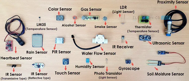
11.) What are the types of the sensor?
- Temperature sensor
- pressure sensor
- Force sensor
- Smoke sensor
- Ultrasonic sensor
- IR sensor
- Proximity sensor
- Touch sensor
- Humidity sensor
- Color sensor
- Tilt sensor
12.) What are the fundamental points that need to consider while designing or selection of sensor?
- The sensor should withstand working/operating temperature.
- The sensor should withstand working/operating pressure.
- It is used to find/sense the presence of workpiesce in the fixture.
- It helps in reducing the manual error.
- It is used to check the quality of welding at particular area.