Week 8:- 3D Finishing - Challenges 1
Q1. What do you understand by the 3D finish process?
3D- finishing is final step of fixture design.
Once all positions of different units are finlaised, gun study is performed, 3D finish is performed, 3D finishing is perfomed.
Designed assembly using a software is virtual represntation of fixture. It should be complete and perfect with all the minor details.
along with design, tree structure shoul be with perfect sequence and names to each invidual part, no repetition as per standards.
Each dimension and positin of each part shoul be nominal .
Either Pin or panel hole can be a master dimension to take referance or a hole ona base plate.
Evary part shoul be nominal to this master dimension.
Also renaming as per guidelines and restructuring tree structure is a part of 3D finishing part.
While perfoming a 3D finish, if required, corrections can be made to ensure proper design so that while actual assemly performed, there wont be issues.
Q2. What are the points need to be taken care of while finishing the design?
For each part in each product, Naming should be uniqe.
All dimensions and positions should nominal.
No sharp edges and corners.
Representation of Machined surface with a color to identify easily.
holes should be concentric and Nominal.
All standard parts, valve, sensors are selected by the standards and located at respective postions.
Colour codes for holes- 1. Threade hole- yellow
2. Dowel Hole- Blue colour
3. OPen hole- cyan color.
Design for Trunking chanel, and Valve box based on the standard provided by customer.
- While finishing the design the nominality of holes is checked which ensures the easy assembly of all the units.
- The hole concentricity & holes sizes are checked which ensures the easy assembly of different parts.
- The gaps between the different units are checked to ensure the proper individual working of different units.
- Designed the rough locators, which help to load a panel in a correct orientation.
- Designed the pneumatic layout for pneumatic connection.
- the gun study is a major and most important part in 3D finishing.
- Selection of sensors, solenoid valve as per requirement, and implementing in design.
- Fasteners are implemented as per the hole size & the standard colour codes as per the customer requirement are applied to differentiate the type of hole wheather its Dowel hole, threaded hole or Clearance hole.
- Renaming of the assembly & the part is done to give every part a different identity so everyone can identify in which assembly this part is going to be fit.
- After doing all these things the model is sent for simulation & 2D detailing.
Q3. What are rough Locators & what is their use?
A rough locator is a guiding part to panel on fixture for manual loading.
Correct Loading Position for rough loactor is finalised by Poka-Yoke proncipal, it assure loading of panel Only in Correct direction.
In case by mistake, operator try to load panel in a wrong way, it wont happen.
It can be a standard part or a make part.
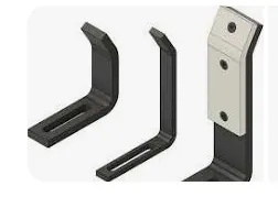
It can have flat surface or a round shape is also possible if needed.
The number of rough locators per panel can vary, depending on geometry of the panel.
Q4. What are the points you need to consider while designing a rough locator?
Following are the points need to be considered while designing the rough locator
- Rough locator should be placed at the edges of the car panel, which it has to guide.
- It has to be placed in the same angle of the car part edge with a minimum distance of 2-5 mm from the edge of the car part.
- It should guide the panel in pin arresting direction.
- It should start guiding the panel before 10 to 15mm to the start of the pin engagement.
- It should be designed with an entry angle for the car panel, it ranges between 30-45 degree.
- It should be designed with slots to mount the easy adjustments.
- The slots should be in the direction of car part guiding.
Q5. What is the gun study process?
Study for positiong weld gun at all the weld spots one by one, and while doing so there should not be any collision of gun and surounding parts.
Once design of various unit sis done, gun Study is performed.
Purpose of gun study is to provide obstacle free path to weld Gun tip and nozzle to each spot.
If the weld gun falls to the fixture unit then, either orientation of gun is changed if required or redesigning of that unit or the repositioning of that unit is done till satisfactory solution is not obtained.
This process is repeated for each spot and path of gun to spot is cleared.
This collective correct postions of gun is called Gun Cloud.
This gun cloud data is further provided to simulation team.
Q6. What re the points need to consider during the gun study?
Following are the points need to consider during the gun study-
1 The axis of weld spot along welding direction must be nominal to the weld surface.
2 The no. of weld spots for the panel, the time required to spot each weld & the total time required to complete all the weld spots.
3 Adequate space between the weld gun and other near by units.
4. If required, adequate changes in near by units can be done to clear the path of gun.
Q7. What is pneumatic routing?
In BIW fixture design, for different operations like Retractable Pin Units, clamp units , slider units and some times Dump units actiations is performed with the help of Pnematic Actuation. For this purpose, compressed air need to supply in required amount to each unit, each station. The safe and systematic network for smooth supply of compressed air from compressor to every invidividual unit is known as Pneumatic Routing.
In order to do so we need different equipment to generate, treat and handle compressed air.
Hoses, control valves, cylinders, fittings tubes are the components of an Pneumatic Router.
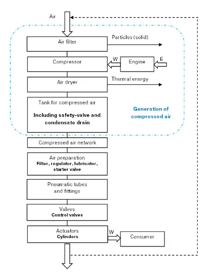
When designing a pneumatic system, typically the individual elements are distributed spatially depending on their task. Although they are spatially separated, they are still connected systematically.
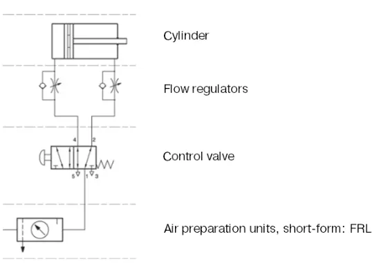
Q8. What is the solenoid valve?
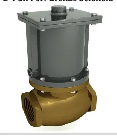
Solenoid valves are electrically activated on/off valve which consists of an electromagnetic actuator (solenoid) and a valve body, typically used to control the flow or direction of air or liquid in fluid power systems.
A solenoid valve is an electromechanically operated.
Compact profile and ease o f control makes a solenoid valve the best choice.
They are used in both pneumatic and hydraulic fluid power functions.
- Ordinary solenoid valves are two-position valves. There is no intermediate, or in-between position.
- Proportional solenoid valves are a special type of solenoid valve that can throttle flow or pressure in response to the electrical input.
- A solenoid valve has two main parts: the solenoid which is responsible for the opening and closing of the valve; and the valve body which contains the fluid and its pressure.
- Solenoids valves can operate with either DC or AC.
In automation, Solenoid valves are used whenever fluid flow must be controlled automatically, such as in factory automation.
These solenoid valves are controlled by microcontrollers or programmable logic circuits with a coded set of actions.
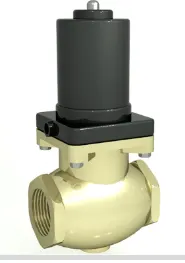
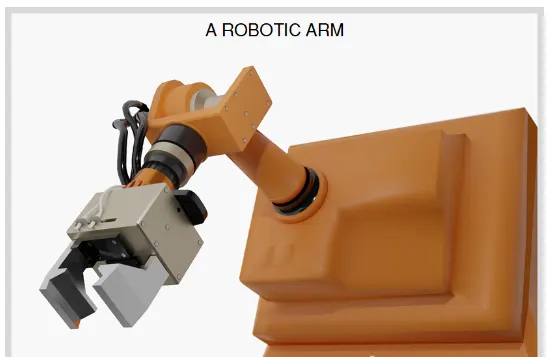
This control of fluid flow allows a defined sequence of actions to be executed precisely and accurately by a robot.
The solenoid-plunger assembly is the valve actuator responsible for opening and closing the valve.
This actuator can be arranged in such a way that the plunger action can either open or close only.
There is no intermediate, or in-between position, henc eno throtteling is possible.
The valve body consists of the pressure containing parts in-contact with the process fluid.
Q9. What is the valve bank?
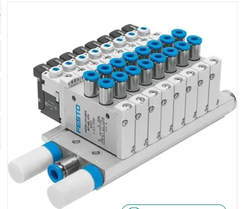
A valve bank- The directional seated valves are available as chained valves in a valve bank.
This facilitates the combination of different circuit symbols or actuation types in order to save space, and such systems can also be used to actuate independent units.
Each Valve operates a single unit. a valve bank is provides single nput and single output port.
From this single, common input, each valves operates.
A valve bank consists of total number of sequences plus one extra valve for future expansio.
From valve bank to each units, hosesand cables are passes through canal called truning channel.
Q10. What is sensor & brief about its application in automation?
A sensor is a device that detects and responds to some type of input from the physical environment in an opertaion.
It is also defined as a device that converts a physical stimulus into a readable output.
The role of a sensor in control system and automation system is to detect and measure some physical effect and providing this information to the control system.
Sensors play a vital role in the industrial automation.
These permit one to detect, to analyze, to measure and process a variety of transformations like alteration in position, diemensiona, exterior and dislocation that occurs in the Industrial manufacture sites.
These sensors also play a pivotal role in predicting and preventing numerous potential proceedings.
Q11. What are the types of the sensor?
In general sensors are classified into various categories -
I- Active and Passive.
Active Sensors are those which require an external excitation signal or a power signal.
Passive Sensors, on the other hand, do not require any external power signal and directly generates output response.
II- According to the means of detection used in the sensor. Some of the means of detection are Electric, Biological, Chemical, Radioactive etc.
III- According to conversion phenomenon i.e., the input can be converted into and the output of desired form.
e.g. Photoelectric, Thermoelectric, Electrochemical, Electromagnetic, Thermooptic, etc.
IV- Last catagory can be uotput type Analog or Digital.
The following are the various types of sensors used in automation:
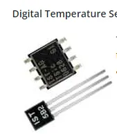
- Temperature Sensor
- Proximity Sensor
- Accelerometer
- IR Sensor (Infrared Sensor)
- Pressure Sensor
- Light Sensor
- Ultrasonic Sensor
- Smoke, Gas and Alcohol Sensor
- Touch Sensor
- Color Sensor
- Humidity Sensor
- Position Sensor
- Magnetic Sensor (Hall Effect Sensor)
- Microphone (Sound Sensor)
- Tilt Sensor
- Flow and Level Sensor
- PIR Sensor
- Touch Sensor
- Strain and Weight Sensor
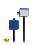
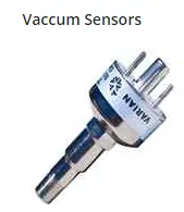
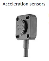
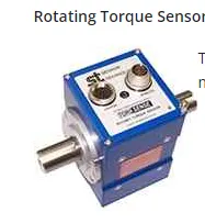
Non-tactile sensors- sensors operates without direct contact to the object in a specified rage around it.
Proximity sensors- A proximity sensor is a non-contact sensor that detects the presence of an object (target) when the target enters the sensor's field.
Sound, light, infrared radiation (IR), or electromagnetic fields may be utilized by the sensor to detect a target, depending on the type of proximity sensor.
2. Photoelectric Sensors detect photo-optical workpieces.
A photoelectric sensor emits a light beam (visible or infrared) from its light-emitting element.
A reflective-type photoelectric sensor is used to detect the light beam reflected from the target.
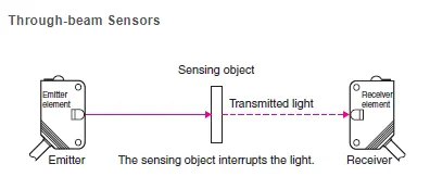
3. LASER- Sensors- It is a sensor that uses laser light or rays for sensing an object.
It makes optics and photo electricity into pictures for working.
It converts light energy into electrical energy. It is used in many industrial automation applications.
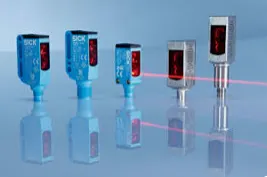
In BIW Fixtures, one can need Sensors to -
1.Check the presence of panel at desired UNit Location,
2. To check position of weld gun at acuurate position.
For these applications Photo electrci sensors, LASER sensors.
Q12. What are the fundamental points that need to consider while designing or selection of sensor?
Sensor selection depends on the application type, the variable operating environment of product and the condition.
Following are some points to conside-
1. Perfect type of Target and Goal
2. To know target size, to decide required sonsors specifications- A sensor light spot be sufficient enought to identify presence of target.
3. Distance between target ans a sensor-
When evaluating sensors based on distance.
Choose a sensor that will provide reliable detection and place it at the optimum distance.
4. Type of surface needed to sense-
5. Measuring Range- Minimum and Maximum qty that a sensor can sense.
While selecting a sensor (temperature sensor, proximity sensor, accelerometer sensor, etc), the measuring range should directly correspond with the physical measuring range so that one can obtain the most precise reading and optimal sensor.
6. Environmental conditions- Surrounding mediun in which sensor will work.
Sensors can be affected by the environmental conditions (such as temperature variation, gas, humidity, chemicals, etc.)
One must be aware of environmental conditions while selecting a sensor.
7. Accuracy and Precesion- One must know accuracy and precesion requirement of the process.
8. Less Power consumtion-
9. Cost should be low- for economical purpose.
10. Repeatability- No. of parts to be sensed, frequency of parts.