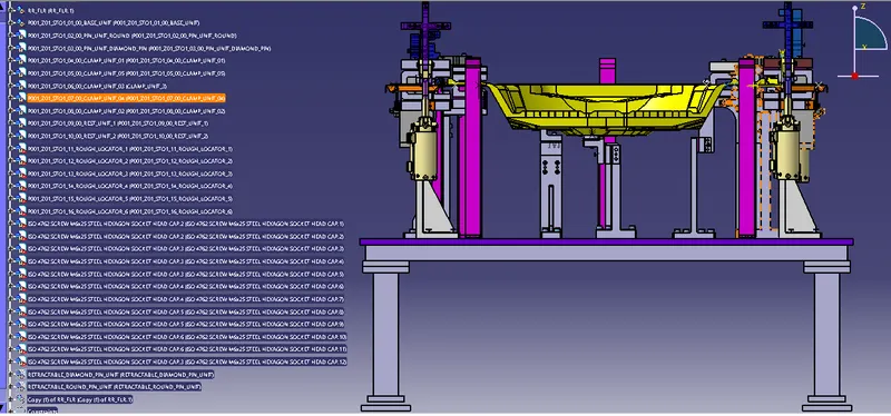
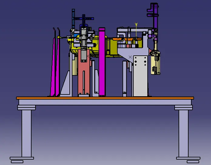
Week 8:- 3D Finishing Challenge 2
--------------------REPORT-------------------------
Aim/Introduction: To perform 3D Finish for various units designed in previous challenges for the input car panel and to create Rough locators
3-D-Finishing-
In BIW Fixture design, after complete design of different units on base plate, finishing of design is performed.
This process is checking for corrective actions to be taken before simulation.
In this step, following points for each unit are checked-
- Each dimension is Nominal, itself and with respect to base plate.
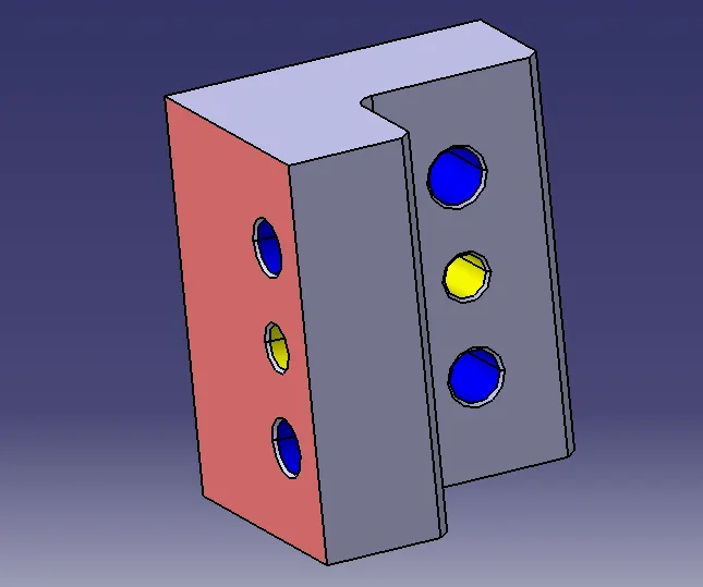
- Representation of Machined surface, Different type of hole
e.g. Threaded hole- is colored yellow,
Dowel Hole – is colored blue ‘
Open (clearance hole) – is cyan colored.
- Holes concentricity
- Proper clearances for panel and adjacent units.
- No clash should present.
- Proper implementation of fasteners.
- Splitting of Mylar at Panel Surface.
- Renaming of parts and sub-assemblies.
- Chamfer and Fillets provided to avoid sharp corners.
This process is 3D finishing of design.
For completing the same challenge, i follow all these steps for each unit like Fixed Pin Unit, Diamond-Fixed Pin UNit, Clamp Units and Rest Units. Also Rough locators are designed and finished in same way.
Few Points Unit wise-
Pin Units- Guiding Dist pf pin and Pnel-3 to 5 mm
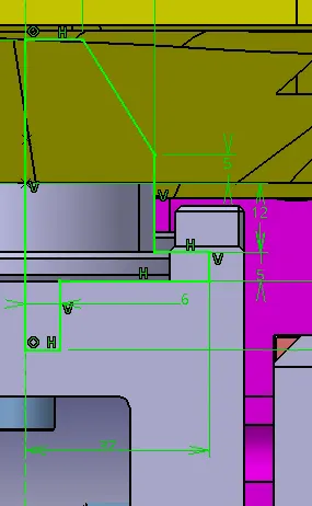
Dist between Pin Collar and Panel 10 to 12 mm.
L block- chamfer, fillet, machined surface are shown and Holes are represented with color codes.
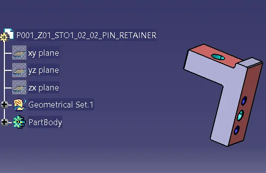
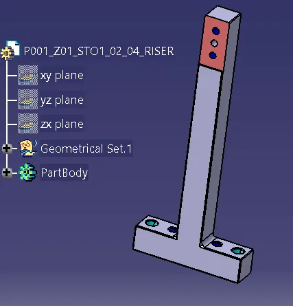
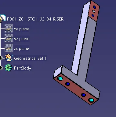
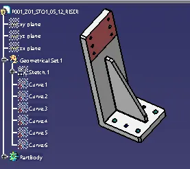
Retainer and Riser also finished with machined surface and holes , chamfer and fillets.
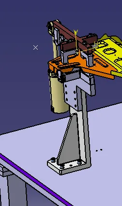
3-D Finishing in Clamp Unit-
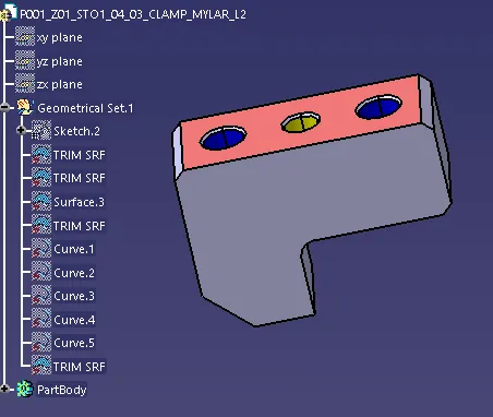
same Methodology is used to 3 D finish a clamp unit.
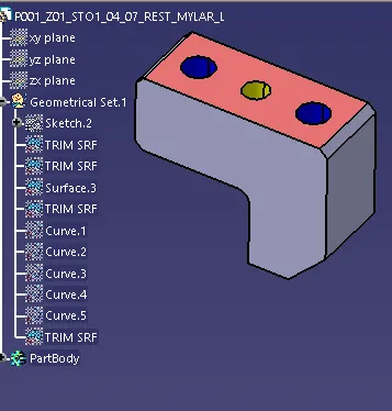
for Clamp and Rest Mylars, Maching surface, Holes colored as per codes, Chamfer, Fillet.
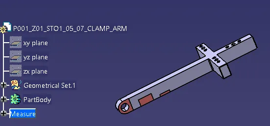
Clamp Arm- Based on Cylinder type, ther are 2 type of clamp arms.
1. Clamp Arm for Power Clamp Cylinder-
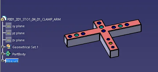
2. Clamp arm for Swivel Cylinder-
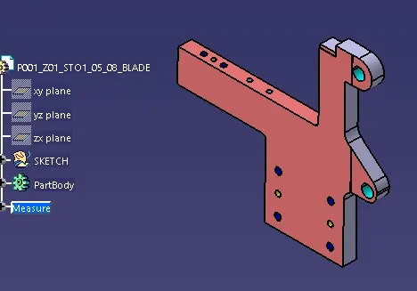
Similarly Spacer block, Mounting plate and blades designs vary as per cylinder.
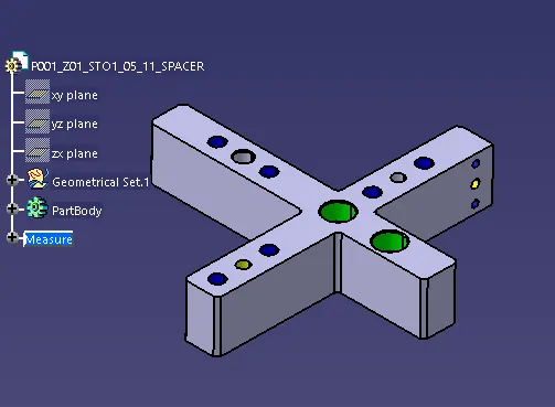
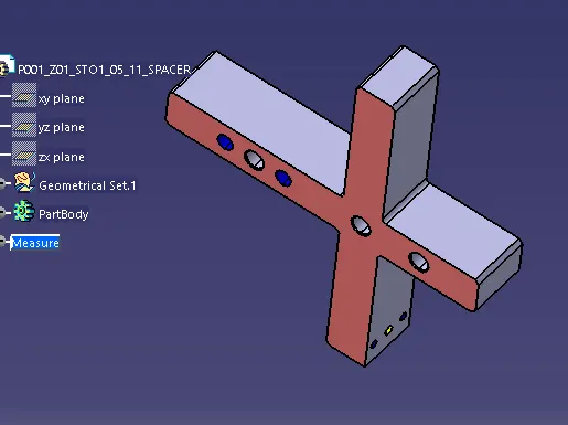
Green Holes are Counter Bored Holes.
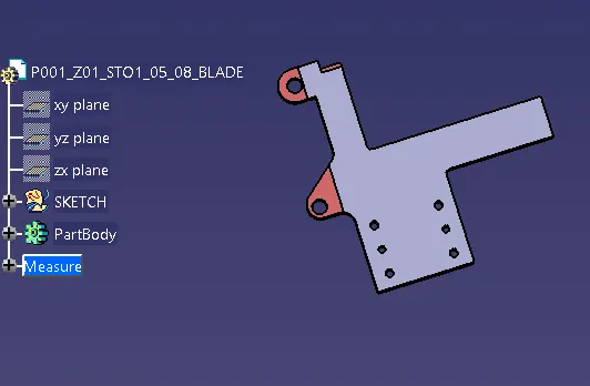
Blade design-
Riser Design-
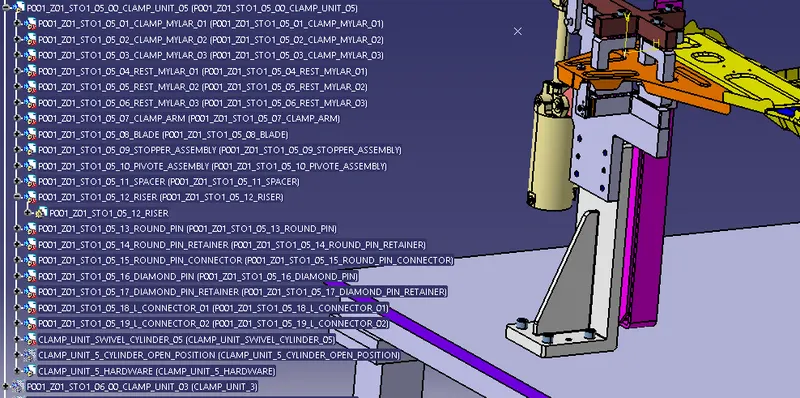
Same Methodology is used for other Units in design.
Rough Locators Design-
Rough locators are provided for guiding the panel ONLY in CORRECT side to its desired position in manual operation.
POKA-YOKE, a Japanese principle is used to design it. It assures Correct Position and Direction of panel on units.
In case by mistake, one tried to load in in a wrong way, it won’t allow loading.
They can either mounted on Base plate or on a mount plate, which further mounted on nearby units’ plate (if possible)
Guidelines to design a rough locator-
- It can be a STD part or a make part
- They should start guiding a panel, 10 to 15 mm before pin guiding starts.
- Slot should be provided for mounting.
- Minimum 3 mm gap should be between rough locator and a panel.
- Angle should be 150 degree.
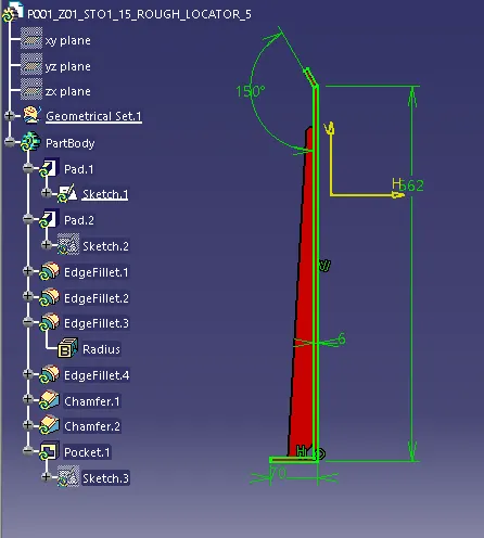
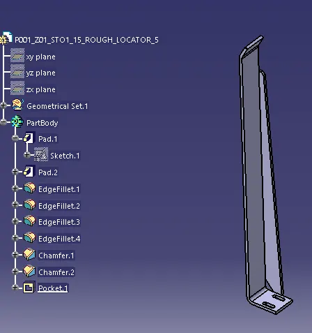
All Rough locators are designed to mount on base plate only, as there is not sufficient space on other near by unis.
They are mounten with a M6 bolt to base plate.
all Rough Locators are at Nominal to base plate.