Week 8:- 3D Finishing Challenge 2
AIM: Perform 3D finish for all units of assembly and Create a Rough locator.
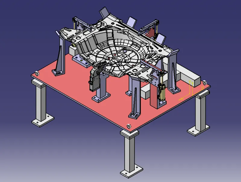
3D FINISHING:
- 3d Finish is a process where the design is being fully finish and to be ready for final simulation and 2d detailing.
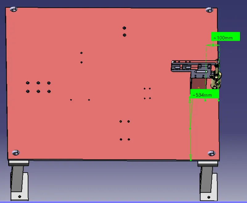
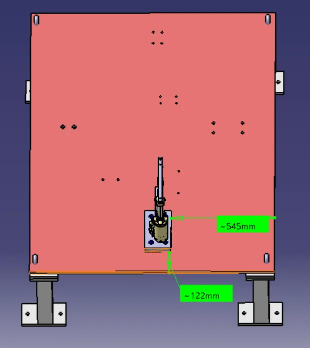
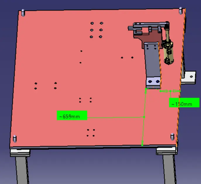
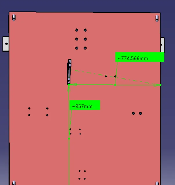
- While finishing the design the nominality is checked which ensures the easy assembly of all the units.
- The hole concentricity and holes sizes are checked which ensures the assembly of different corridor.
- The gaps between the different units are checked to insure the proper existent working of different units.
- Design the rough locators, which helps to loading a panel in correction exposure.
- Design the pneumatic lay spin for pneumatic connection.
- Gun study is major and most important part in 3d finishing.
- Selection of sensors, Solenoid valves as per the demand and applying in design.
- Fasteners are applied as per the hole size and the standard colour codes as per the client condition are applied to separate the type of
hole whether its dowel hole, Threaded hole or allowance hole. - Renaming of the assembly and the part is done to give every part a different identity so everyone can identify in
- which assembly this part is going to be fit.
- After doing all these effects the model is transferred for simulation and 2d detailing.
Points Need to Be Taken Care of While Finishing the Design
The following are the points taken into consideration while finishing the design.
1. Hole Concentricity and Hole Sizes:
Concentricity of a hole refers to the tolerance allowed for the deviation between the location of the entrance and exit of a hole and hole sizes are checked for easy assembly while finishing the parts.
2. Machining Area:The machining area in every part should be defined and the machining area should be highlighted by using standard colour code. Machining is to be done on parts to properly Mount with mating parts. Machining only on desired faces reduces cost and save time. And also Machining increases accuracy of dimension. So before going to simulation or detailing machining area should be defined.
3. Nominality:
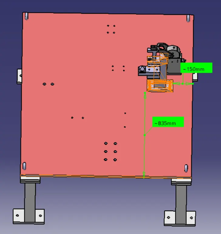
All unit’s dimension should be maintained nominal to facilitate easy assembly of the unit.
4. Holes Colouring Standard:
In a 3D finish hole colouring should be done because it helps to identify what type of hole it is. It depends on customer standards. Customer specific colour like:Dowel hole should be given blue colour. Threaded hole should be coloured with yellow.Counter bore, open hole should be given cyan blue colour.
5. Pneumatic Lay outing:
Pneumatic lay outing is collection of different pneumatic pipes which work as a inlet to the pneumatic cylinder. It should be done properly for proper functioning of the units.
6. Gaps Checking:
The gaps between the different units are checked to ensure the proper individual working of different units.
7. Fasteners Implementation:
Fast should be implemented in all the units as per the requirement and load on the part.
8. Avoiding Clash Between Different Parts:
Proper gap should be maintained between units to avoid the clashes between the different units.
9. Mylar Splitting as Per Panel Profile:
Mylar splitting as for panel profile should be confirmed while finishing the design.
10. Proper Renaming of Parts or Assemblies as Per the Standards:
Proper renaming of parts and assembly should be done while finishing the design and hence we can identify each and every part easily with Unique Identification.
ROUGH LOCATORS :
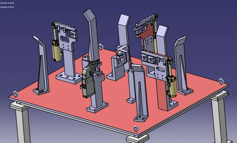
It is used to locate car panel and also guide the operator to load the car panel in the fixture perfectly. Standard Rough locators are also available. It can be also called as fool proofing method. Because without rough locator the part cannot be loaded in correct position
Uses:
- It is used to locate the car panel in the fixture.
- It is also known as Pokayoke or Fool Proofing as part is located in fixture accurately
- Accuracy is maintained due to use of rough locators.
4. The points you need to consider while designing a rough locator.
- Height of rough locators should not be more than the permissible ergo height of the fixture.
- The entry poit/ top point of the rough locator must be 10mm-15mm above the panel surface.
- Rough locators should habe adjustment in the direction of guiding plane.
- 2mm gap to be maintained between rough locator and panel at the time of design and we can provide adjustment of 5-10mm in the positive or negative direction of guide plane.
- Rough locators can be rod type or flat type, depending upon the standards and other conditions.
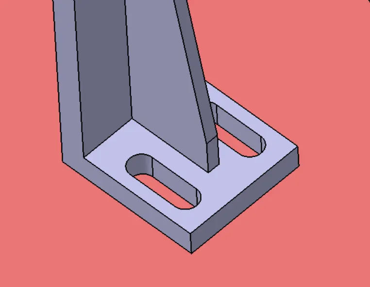
Slot given to rough locator to adjust the position:
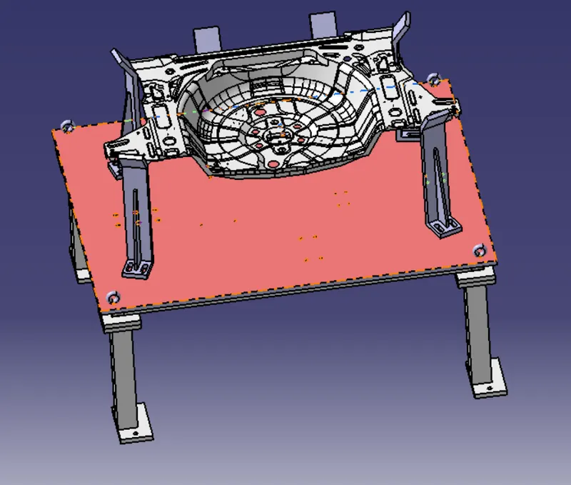
Positioning of rough Locators on the Base Plate:
Gun study:
It is the process of checking whether the gun is able to weld the selected car panels. The below images shows the weld gun dong spot welding and the weld location where the spot is created on the car panel. Gun study is necessary as the BIW car panels are complex in share and sixe. In 3D software gun study is done by actually introducing welding gun in fixture that we have designed. According to that units are designed so that there's no problem while welding process.

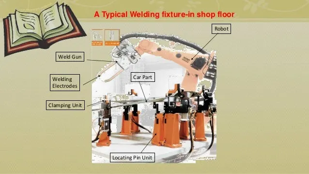
The points need to consider during the gun study :
- The axis of weld spot along weld direction must be normal to the weld surface
- Total no. of weld spot and time required for each is calculated for knowning total time required for welding that car panel.
- Robot cycle time is calculated while doing proper gun study.
- Collision checking is done on simulation software to check whether the welding process is done without ant collision with any units in fixture.
FIXTURE ASSEMBLY:
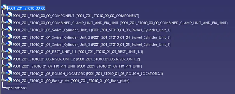
Renaming and structuring of the design tree:
Renaming of the design tree is done. and structuring design tree in way that its simple to identify the units. some units use multiple time those are easy to
identify by its name.
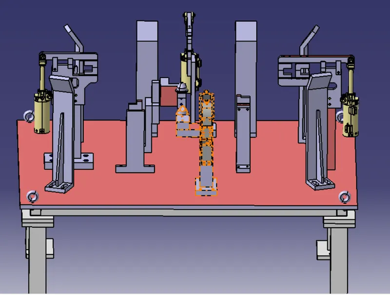
Base Unit: Base unit is the unit designed to mount all the other units (clamp unit, pin unit, rest unit etc..) of the tool, also other parts necessary for a tool like pneumatic valve box, trunking cable path will also be mounted on to a base unit.
The base structure 50x50x2xL Square tubing is used and the pedastal Support is provided with 80x80x5xL square tubing.
Typical parts of Base units :-
Base plate:- Base plate is a machined plate of 25 to 40mm thickness made of steel and aluminium , on which the holes are drilled to mount the individual units like clamp unit, pin unit,etc., of a tool.
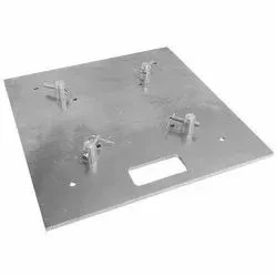
Pedestal: A pedestal is a part which connects the base plate to the floor plate. A pedestal is a standard part in general , and in some cases it can be a welded frame integrated with the base plate.
- A standar pedestal can be of different height and different sizes.
- Depends on the size of the base plate, the number of pedestal varies for load distribution.
- A pedestal are of different types with different inclinations.
Trunking channel: A trunking channel is a duct which accomodates all the pneumatic and electrical hoses and wires for the units of the tool.
Valve Box: Valve box is a standard part which will accomodates the pneumatic valves for the units.
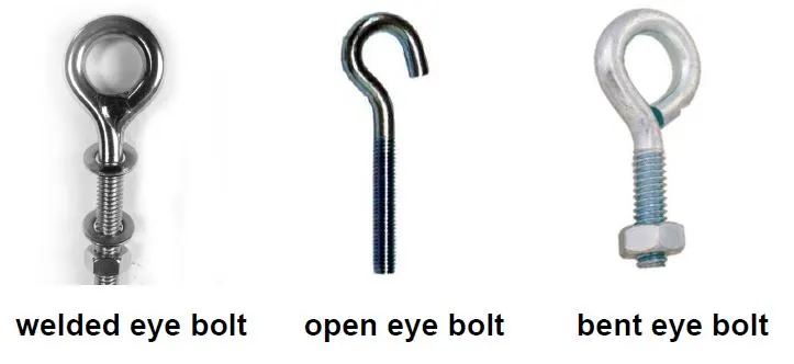
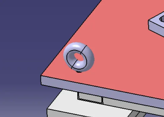
Eye Bolt: Eye bolts are used for the transporting of the tool, using lift hooks, Fork lift holes will also be provided in some cases for transporting purpose.
Floor Plate: Flooe plate is grouted to the floor with fixed bolt on the ground. Floor plates are also called as foundation plates.
- There will be a clearance of 10mm maintained between the pedestal base plate and the floor plate.
- This clearance will be used by levelling screws, for levelling the entire tool.
- Weld bars are be used to weld the positions permanently, After levelling is done.
- A weld bar is a plate along the sides of the base plate of the pedestal.
Weld bars: These bars are used to position the fixture. Weld bar is steel plate placed along side of base plate of pedestal.
Design Methodology:
The points need to account while designing a Base Unit as below:
- Working Height: it is depend upon type of operation whether it is manual welding or robotic welding height of base unit decided. For manual welding fixture working height must be 850 to 1100mm for ease in welding operation for the operator.
- Selection of Eyebolt depend upon weight of fixture. According to the weight of fixture tapping for eyebolt is provided on base plate like M24 or M20. Generally four eyebolt are provided on base plate.
- Depending on no of units, sizes and weight base are designed. base designed are made up of square or rectangular tubes or c channels with machined plate.
- Generally four dowel holes are provide at four corner of base plate with its coordinates displayed on aluminium plate
- Base unit is designed in such a way that there is mon possibility of deflection vibration.
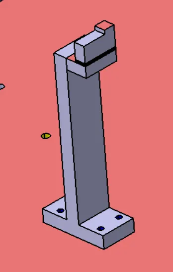
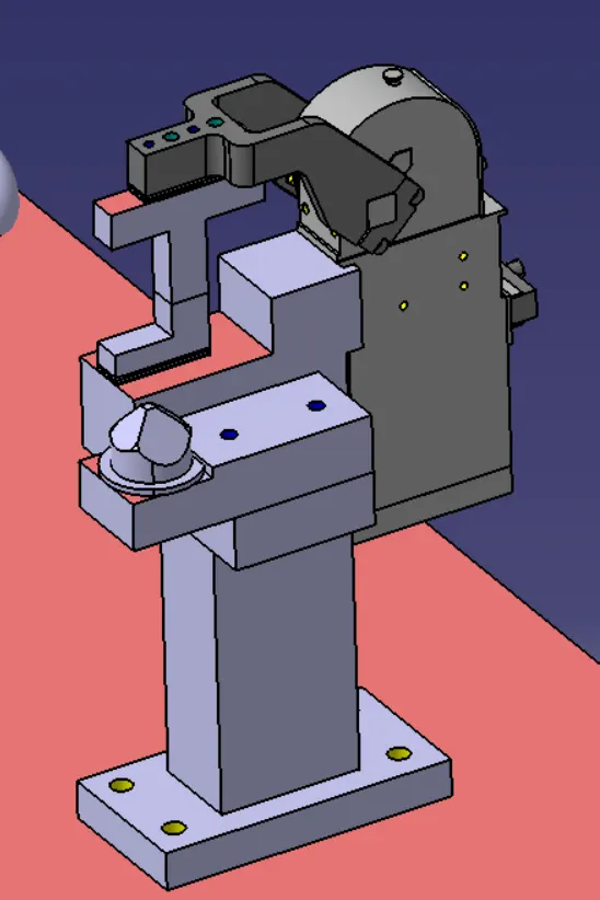
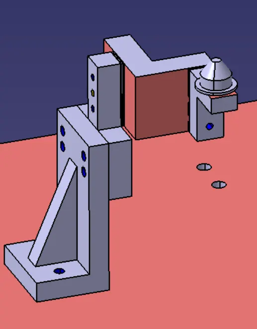
MARKING OF MACHINING AREA:
THE HIGHLITED AREA IS THE MACHINING AREA
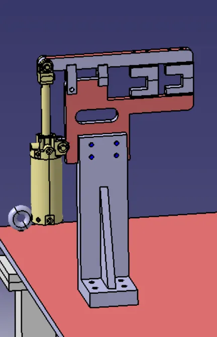
CHECKING THE NOMINALITY OF THE UNIT:
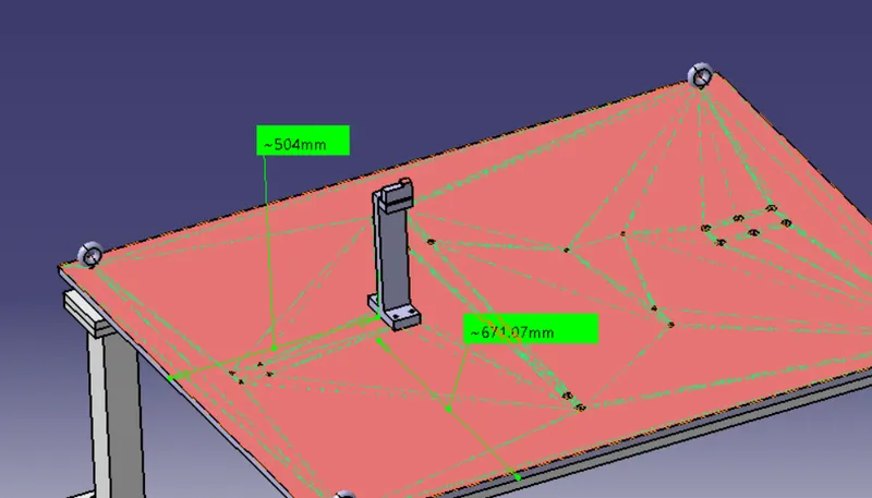
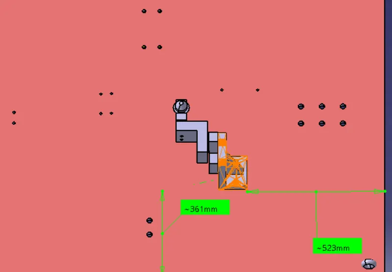
COLOURING STANDARDS:
DOWEL - BLUE COLOUR
YELLOW - THREADED HOLE
BLUE - CLEARANCE HOLE
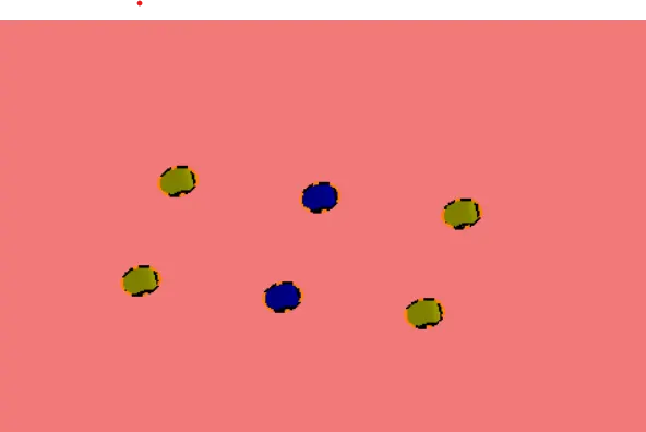
HOLE CONCENTRICITY:
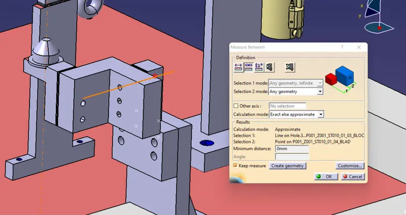
RENAMING OF ALL THE PARTS OF UNITS:
CONCLUSION:
Hence, 3D finishing is performed on the designed assembly of fixtures and rough locatorss were designed for the given panel.