Week 7 State of charge estimation
For this challenge, download the simulink model from the link given below and extract the file
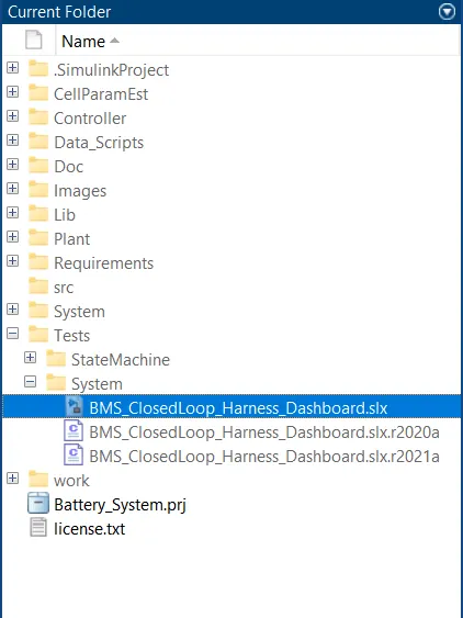
Open MATLAB and make the extracted folder as current folder. From the folder list open Battery_System_R2020a\Tests\System\BMS_ClosedLoop_Harness_Dashboard.slx
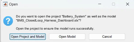
From the pop up window select "Open Project and Model"
BMS
Battery management system (BMS) is technology dedicated to the oversight of a battery pack, which is an assembly of battery cells, electrically organized in a row x column matrix configuration to enable delivery of targeted range of voltage and current for a duration of time against expected load scenarios.
The oversight that a BMS provides usually includes:
- Monitoring the battery
- Providing battery protection
- Estimating the battery’s operational state
- Continually optimizing battery performance
- Reporting operational status to external devices
Test Harness:
To Create a test-specific simulation environment for the model we use a test harness method.
Here, we isolate the individual blocks for unit testing and add inputs, verification logs, and dashboard blocks, and perform closed-loop testing by adding physical plant models to the test harness Test.
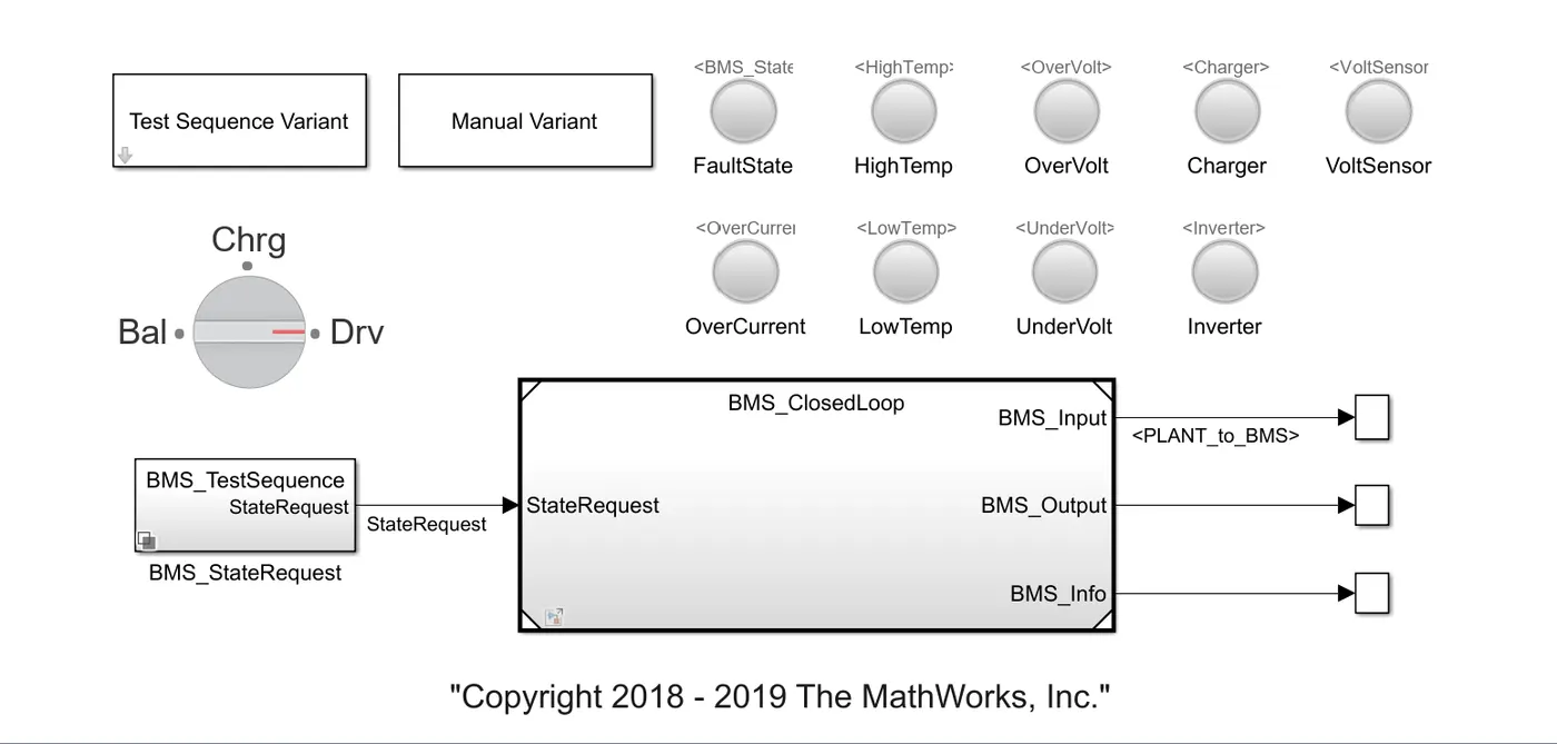
BMS Closedloop Test harness Dashboard Model
Components
* Lamps are given indicate fault state, high temperature, over current, charging voltage, sensor operation, low temperature, and under-voltage. If any fault in these readings, indication will be given and if all in good conditions, it is indicated by green indication.
*Rotating switch to select between different modes
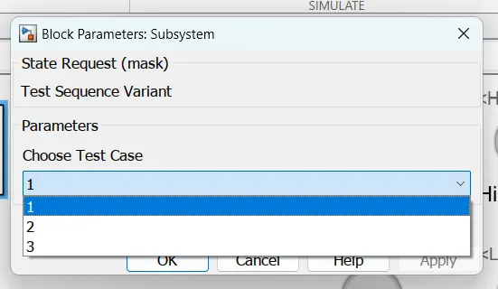
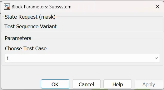
*Test sequence variant is used to select the test sequence. There are 3 test sequence programmed.
Sequence 1

- In this sequence, first 3000 seconds, BMS is in driving mode.
- After 3000 seconds, for the next 1000 s BMS is in balancing
- After balancing, charging mode selected for next 5000sec
-For the remaining time, again BMS in balancing
Sequence 2

- In this, for the first 10000sec BMS in driving mode and remaining time in charging mode
Sequence 3

- In this sequence, BMS is in charging mode only
BMS CLOSED LOOP
The closed loop consist of two subsystems BMS ECU and Plant
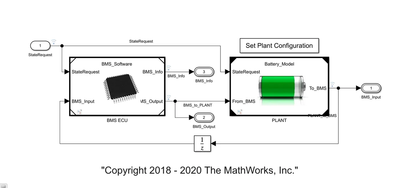
BMS ECU:
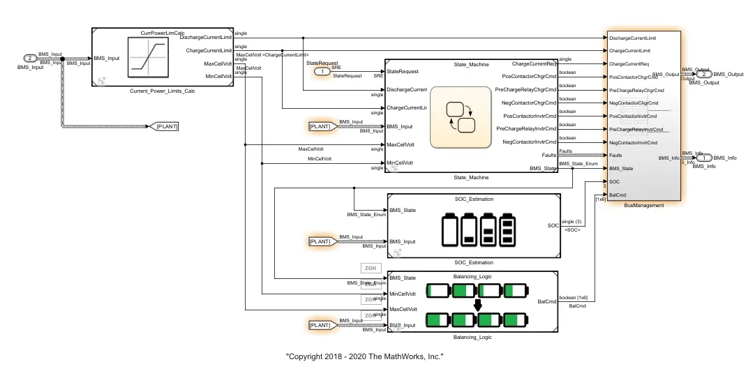
BMS ECU is the control unit which controls,protects,balance and manage the battery,
It consists of subsystems
current power limits calculation - This block controls and calculate the charge current limit,discharge current limit,min voltage of cell and max voltage of cell.
state machine - This gets the input from the state request,based on the state request st,ate machine goes through the logic of charging,discharging,balancing by open the contactors of the battery,inverter and monitor the fault states and give the BMS output.
SOC estimation - SOC is accurately estimated by coulomb counting and using the Kalman filters,
Balancing logic - This is the subsystem which consist of state machine which will balance the cell according to the BMS state,It will activate balacing or deactivate the balancing according to the BMS state requirements.
PLANT:
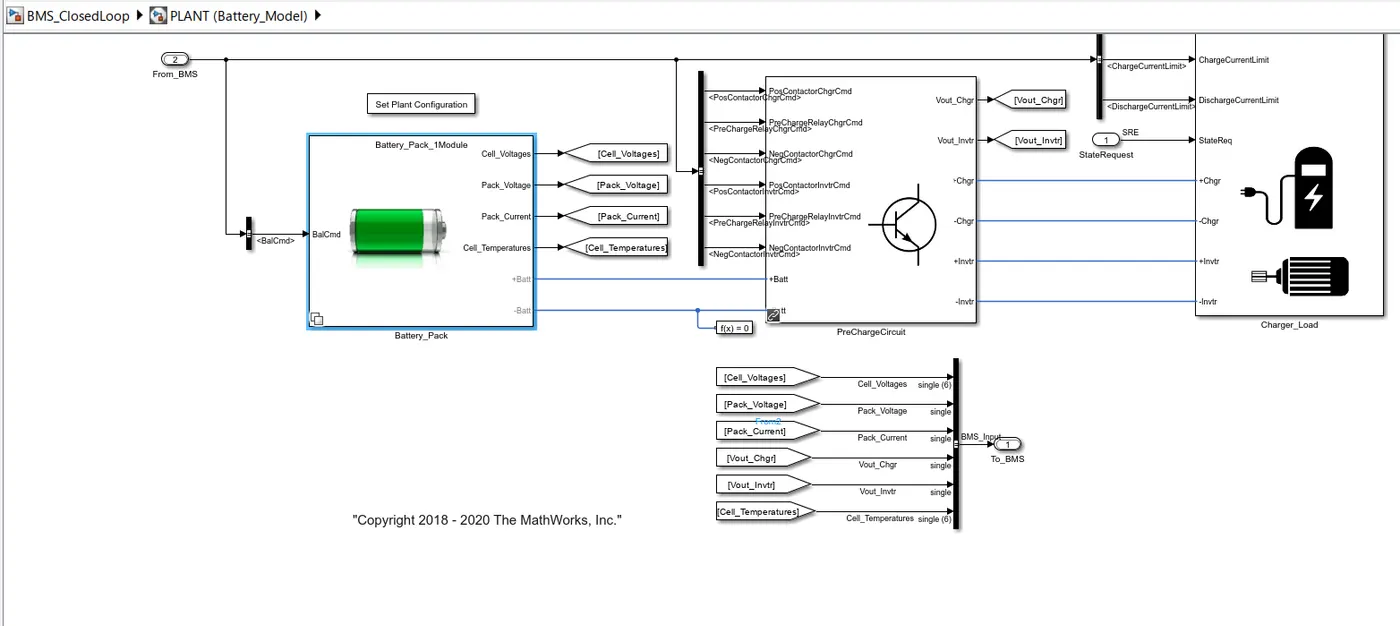
This consist of battery pack, precharge circuit and charger & load.
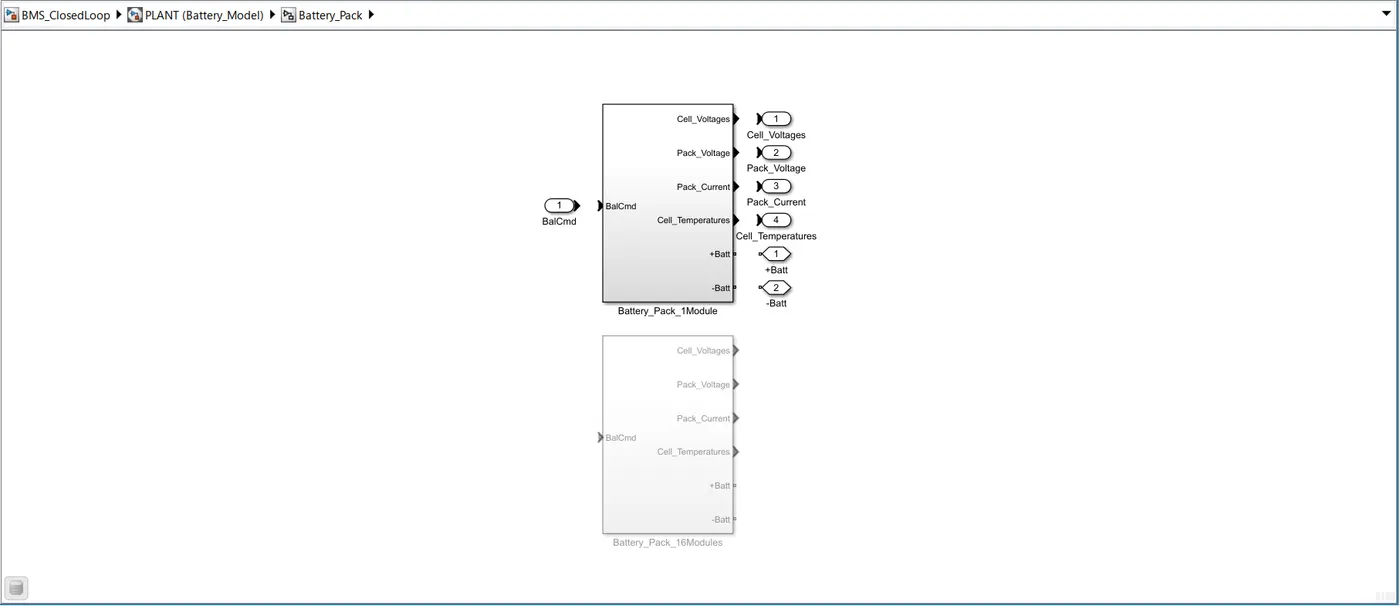
Battey pack - consists of the cell with some configurations of voltage and capacity. This has 2 different pack configurations consisting of 16 cell pack and a single cell pack.
Precharge circuit - It is used to limit the Input current to slowly charge the downstream capacitance.
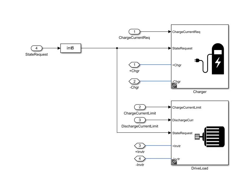
Charger and Load - charger subsytem is with controlled current source which charges the battery according to the BMS state and drive load subsystem consist of load requirements of the drive cycle which draws the current and discharge the battery according to the load.
After the compilation is successful the scope opens up. The scope consist of the measurements of cell voltages,cell temperatures,SOC,pack current,BMS State,Balancing command.
Case 1:
The 3 test cases from harness dashboard is simulated one by one.
Sequence 1
Sequence 1 is selected and model is simulated
Observations:
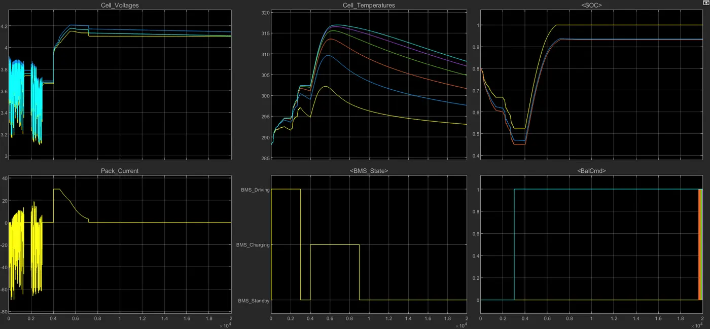
Driving state (0-3000 secs):
- All the cells for the first 3000 secs are in driving state so the discharge of all the cells occurs and its varies in the range of 3.1 to 3.9 V (min and max.).
- Cell temprature increases from 288K to 305 K.
- SOC also reduces from 80 % to 45%.
Balancing State (3000-4000 secs):
- After 3000sec for next 1000 secs, cell balancing occur and the Modules are in standby mode and they are having constant voltage near about 3.7V.
- Cell temperature reduces slowly as no current flow through the cells during balancing.
- SOC is also constant during this period at 45% .
Charging and Balancing state (4000- 9000 sec):
- After 4000 sec the charging occurs and the cell voltages increased from 3.7 to nearly about 4.2 V in Constant current mode with current of nearly 30A and then the constant voltage charging starts and current reduces from 30A to 2.5 A Charging and balancing of cells occur till 9000 sec.
- Cell temperature also start to increase exponentially upto constant current region and reduces as current flow reduces in constant voltage mode.
- SOC also increases from 45% to 94%.
Post charge Balancing state(9000- 20000sec):
- After 9000 sec the post cell balancing starts under standby mode.
- Cell temperature reduces in this mode and tries to reach the ambient temperature.
- SOC remains constant to 94%.
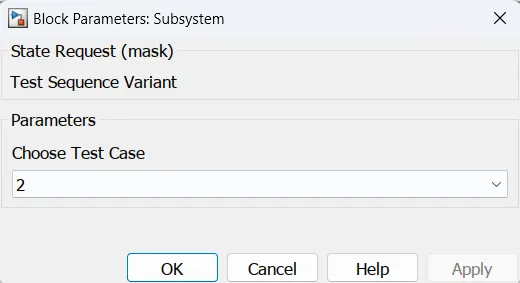
Sequence 2
Sequence 2 is selected and model is simulated
Observations:
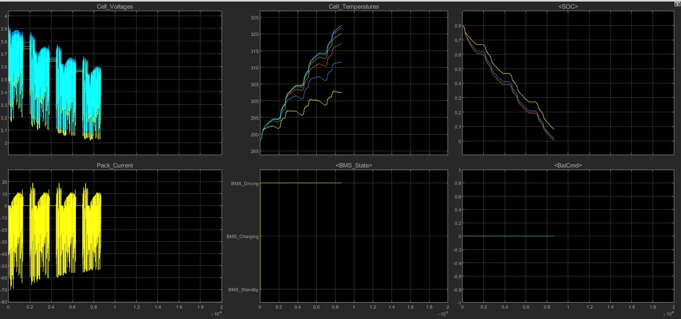
Driving State (0-10000 sec):
- The cell voltages varies from maximum 3.9V and reduces to 3.05V as cutoff voltage upto 9000 secs.Entire capacity drained at 8692 secs..
- The pack current discharges upto maximum 70A
- Here cell 1 having lesser temperature variations from 288K to approximately 302.5K. Cell 6 is having higher temperature variation from 288K to approximately 322.5K.
- SOC reduces from 80% to 0% (cell got fully drained) in the drive mode under 8692 sec.
- Some stand by mode conditions are in between the drive modes.
- balancing of cells are not performed as shown as balance states are in 0 for entire drive mode.
Sequence 3
Sequence 3 is selected and model is simulated
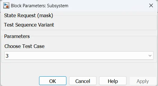
Observations:
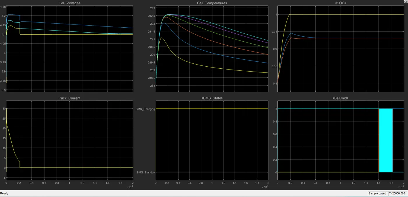
Charging state (0-20000 sec):
- Cell Voltages increases from there intial values and after 2000 sec they got constant .
- Pack current initally start from 0 to 30A and then start decreasing when the constant voltage mode is there to 2.5 A and got full charged upto 2000 sec.
- SOC was initally 80% and in 2000 sec it got fully charged that is 100%.
- Cell temperature starts to incraeses initally and when battery got fully charged then decrease down to the ambient temperature.
- Balancing of all cells is done at end of simulation.
Case 2
SOC:The state of charge (SOC) is a measurement of the amount of energy available in a battery at a specific point in time expressed as a percentage. For example, the SOC reading for a computer might read 95% full or 10% full. The SOC provides the user with information of how much longer the battery can perform before it needs to be charged or replaced. Understanding the state of charge is important because understanding the remaining capacity of a batter can help make a control strategy. SoC is usually expressed as percentage (0% = empty; 100% = full). An alternative form of the same measure is the depth of discharge (DOD), calculated as 100 - SoC (100% = empty; 0% = full). SoC is normally used when discussing the current state of a battery in use, while DoD is most often seen when discussing the lifetime of the battery after repeated use.
Usually, SoC cannot be measured directly but it can be estimated from direct measurement variables in two ways: offline and online. In offline techniques, the battery desires to be charged and discharged in constant rate such as Coulomb-counting. This method gives precise estimation of battery SoC, but they are protracted, costly, and interrupt main battery performance. In general there are five methods to determine SoC indirectly
- chemical
- voltage
- current integration
- Kalman filtering
- pressure
Coulomb-counting
Coulomb counting, calculates the SoC by measuring the battery current and integrating it in time. Since no measurement can be perfect, this method suffers from long-term drift and lack of a reference point: therefore, the SoC must be re-calibrated on a regular basis, such as by resetting the SoC to 100% when a charger determines that the battery is fully charged
In this method, a discharging/charging current I(t) is measured and integrated over time to calculate the amount of energy remaining inside the battery. In this method, SOC is taken at the previous time step SOC(t-1) and the amount of energy removed/added at the current time step is subtracted/added from the SOC of the previous time step SOC(t-1) to obtain the amount of energy present in the battery at the present instant.
`SOC(t)=SOC(t-1) + (I(t))/(Q(n))*Deltat`
In the model, a subsystem is created for the SOC estimation as shown below
Once the SOC estimation is opened, different subsystems corresponding to different strategies for SOC estimation is given including kalman filtering.
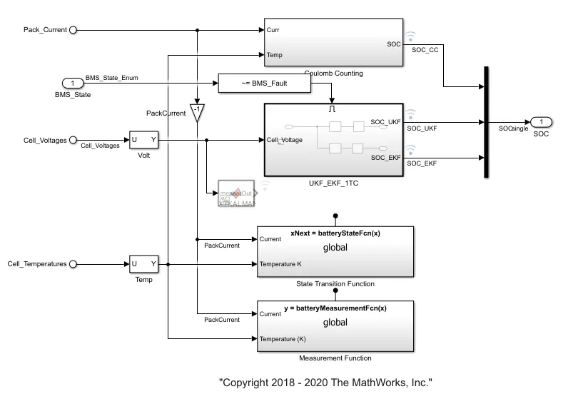
Coulomb counting subsystem is opened and the inputs to the model are cell temperature and pack current.
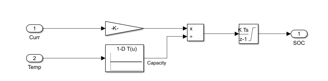
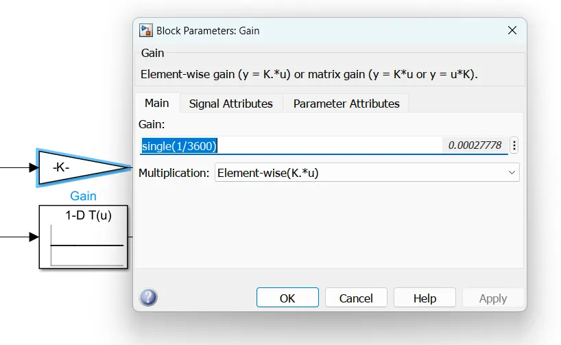
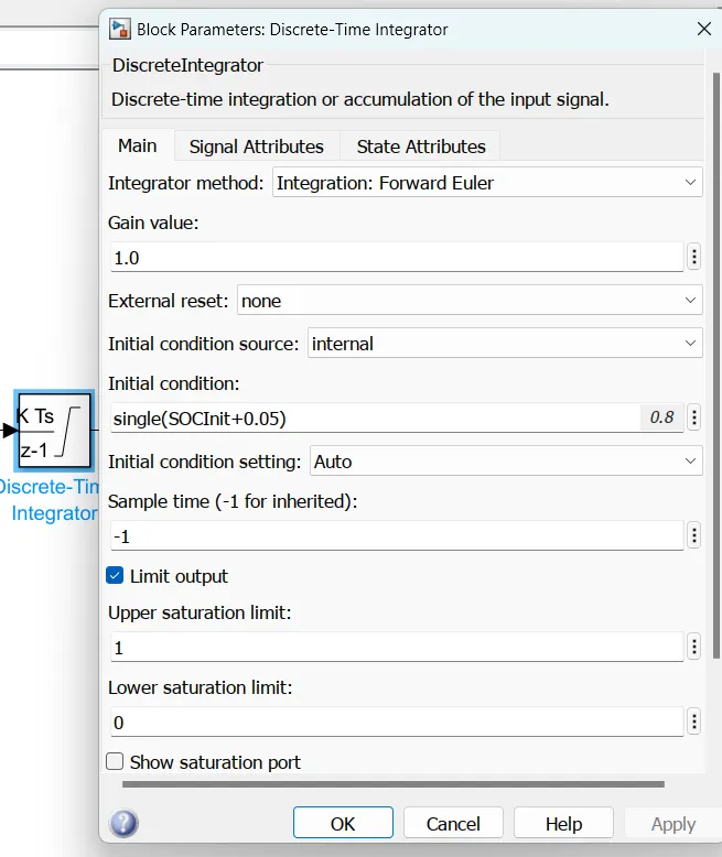
The pack current is passed through gain which will divide the value by 3600 to convert it to Ah. cell temperature capacity factor is taken from the look up table data and divided from the current value. Now the current is integrated over time to get the SOC value between 0 and 1 and this value can be multiplied by 100 to get the SOC in %.
Conclusion
All 3 test sequences were simulated and different parameters analysed. Observed that cell temperatures increases while driving and also in charging in CC condition while temperature reduces during cell balancing, standby and charging in CV mode.
Coulomb counting method is studied and the model is explained.