Week -2
1. Doorbell model
Aim:
To Create a simulink model for a doorbell and observe the movement of the plunger
Doorbell model is created in simulink using various blocks as shown below
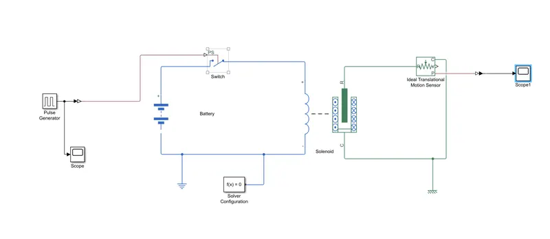
1. Pulse generator : This block is used to create a simulink pulse signal according to the parameters mentioned .
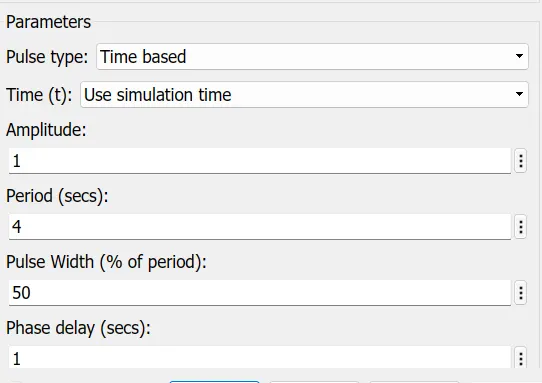
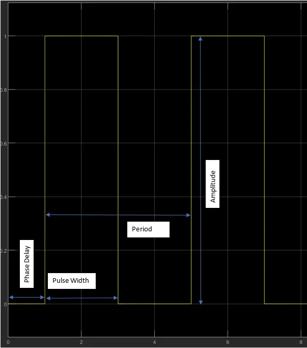
When the time is greater thann the phase delay, the pulse is on and the vertical displacement of pulse will be equal to amplitude. The various parameters of the pulse to be confogured are given in the above graph. Pulse width is given as a % of period.
2. Simulink to PS converter: this block is used to convert the simulink pulse signal to a physical signal
3. Switch : this is used to switch ON & OFF the circuit w.r.t the physical signal from the converter
4. Battery: DC source
5.Solenoid : This block simulates the actions of a solenoid (both electrical 7 mechanical). the power supply is connected to the coil and the mechanical motion of plunger is measured using a sensor
6. Ideal translational motion sensor is used to measure the movement of the plunger
7. The movement of the plunger movement is converted in to a simulink signal using PS simulink converter and plotted using a scope.
Electrical refernce is given to the electrical circuit and mechanical reference to the mechanical side of the circuit.
The results of the model is as given below
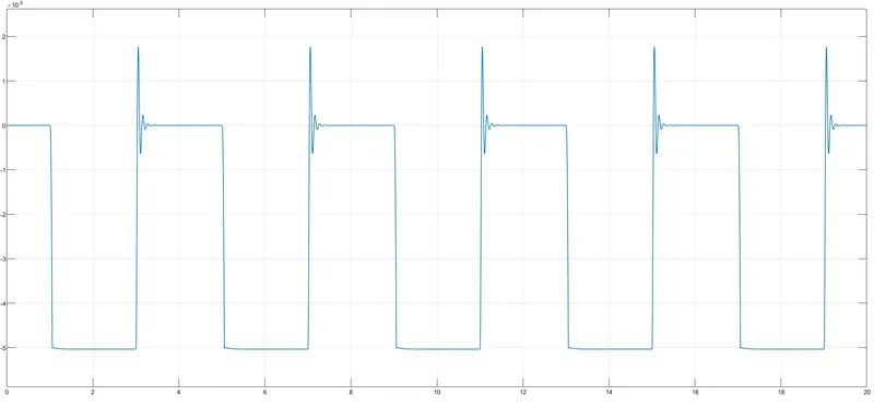
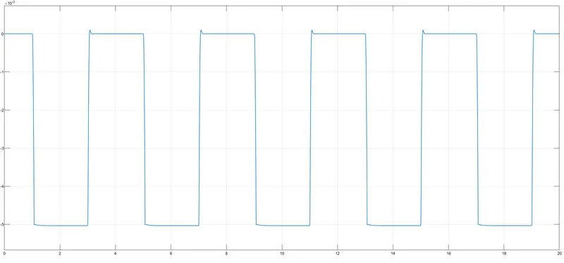
The movement of the plunger can be smoothened by increasing the dampening constants of the spring. Once the damping factor is 5 Ns/m, the movement is much more smoother as given below.
2. Using a Thermistor to switch ON & OFF a fan
Temperature source – 20 from 0 to 10 seconds, 27 from 10 to 30 seconds, 23 from 30 to 50 seconds.
Fan conditions – ON if temperature above 25 degrees , OFF otherwise.
Aim
Create a simulink model to use thermistor to sense temperature of a heater and turn on/off the fan as per the given conditions
Theory:
Thermistors are a type of semiconductor, meaning they have greater resistance than conducting materials, but lower resistance than insulating materials. The relationship between a thermistor’s temperature and its resistance is highly dependent upon the materials from which it’s composed. The manufacturer typically determines this property with a high degree of accuracy, as this is the primary characteristic of interest to thermistor buyers.
Thermistors are made up of metallic oxides, binders and stabilizers, pressed into wafers and then cut to chip size, left in disc form, or made into another shape. The precise ratio of the composite materials governs their resistance/temperature “curve.” Manufacturers typically control this ratio with great accuracy, since it determines how the thermistor will function.
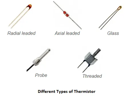
Thermistors are highly accurate (ranging from ± 0.05°C to ± 1.5°C), but only over a limited temperature range that is within about 50°C of a base temperature. The working temperature range for most thermistors is between 0°C and 100°C.
Thermistors are employed in a broad array of commercial and industrial applications to measure the temperature of surfaces, liquids and ambient gasses.
NTC thermistors are resistors which have a negative temperature coefficient. It means that the resistance is reduced based on increasing temperature. They are typically introduced as resistive temperature transducers and current-limiting systems.NTC thermistors are resistors which have a negative temperature coefficient. It means that the resistance is reduced based on increasing temperature. They are typically introduced as resistive temperature transducers and current-limiting systems.
PTC types of thermistor are instruments with a positive temperature coefficient. They operate in the opposite method of an NTC thermistor which means that the resistance improves with an increase in temperature. They are typically not common but can provide a particular niche function like using in a safety fuse. 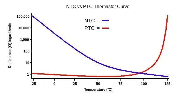
Fan control using Thermistor
The model created in simulink is as given below
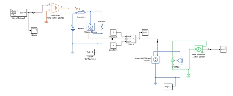
Here in the problem, the conditions of temperature are given. So first step is to create a signal accordingly. All temperture values are converted to kelvin and signal is created with the help of signal builder. We can specify the values of time in x axis and tempreture in y axis. 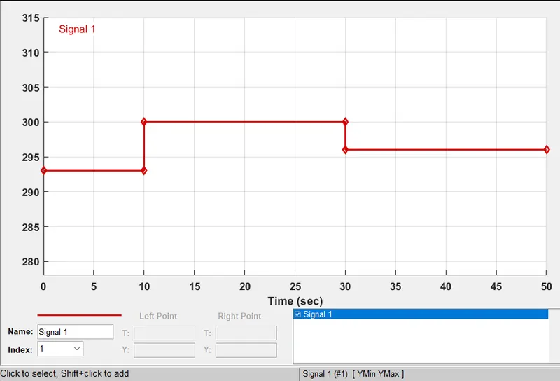
Now we use a controlled Temperature source which will output a specific temperature as per the physical input signal given. The simulink signal created in the signal builder is converted to Physical signal using simulink PS converter. The temperature refernce is connected at port A and port B is connected to thermistor
The thermistor is connected in a circuit with a battery and an additional resistor to measure the resistance of thermistor and a volt meter is connected across the resistor to measure the voltage drop across. The threshold value of voltage is measured when the temperature given to the thermistor is 25 deg C. The output of the voltage sensor is given to a switch. if the voltage is less than the threshold value, the switch will output 0 and when the voltage is higher than the threshold value, the output is 1.
Now if the model is compiled, it is seen that when the temperature is above 25 only, the signal is 1which means that the device connected to this switch will only be ON when the temperature is above25 degrees. 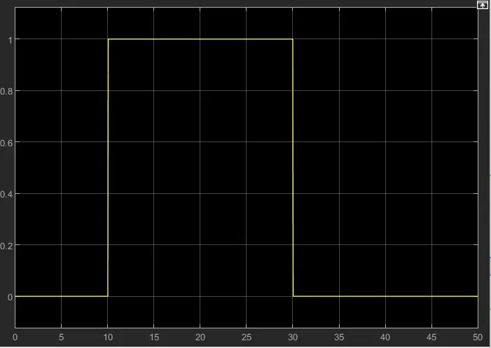
Now we can actually use this signal from the switch and use it to run a DC motor. For this we have to use the following blocks
Controlled Voltage Source: this block will maintain a constant voltage irrespective of the current passing through it. The voltage is supplied with respect to the signal from the switch
Converter : The signal from the switch is converted in to a physical signal
DC motor: This block simulates the operation of a DC motor. The controlled volatge source is connected to the electrical terminals of the DC motor
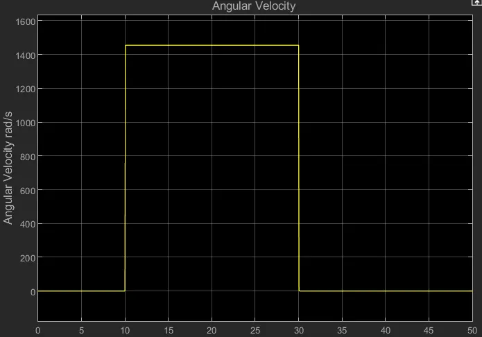
Once the voltage is supplied, the DC motor will start rotating.
Ideal rotational motion Sensor: This is used to measure the rotational motion of the DC motor. A scope can be used to plot the values