Week 7 State of charge estimation
1. Simulate the 3 test cases from the harness dashboard and write a detailed report on the results.
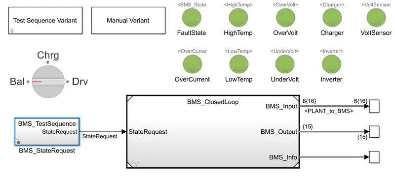
BMS Closedloop harness dashboard:
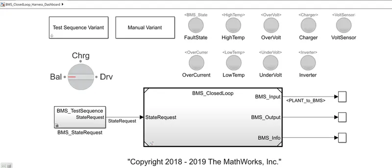
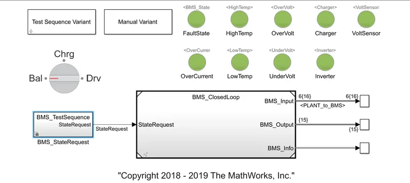
A harness dashboard has a test sequence variant that has 3 different test cases. In a dashboard, the green color indicates that a particular parameter working correctly and Red indicates there is an error in that parameter. here, the parameters are fault state, high temperature, Over voltage, Charger condition, Over current, Low Temperature, Under voltage, and inverter condition.
There are three modes of the driving condition of the vehicle, there are
Driving: Discharging of battery and vehicle is moving),
Charging: The battery is charged at a standstill (Plugin )or running (due to regenerative braking ), and
Standby: neither charging nor discharging of battery and vehicle in standstill condition)
The simulation time is set to 20000 sec.
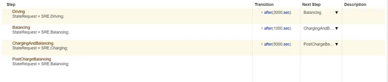
In a 1 test sequence:
Scope for test sequence 1:
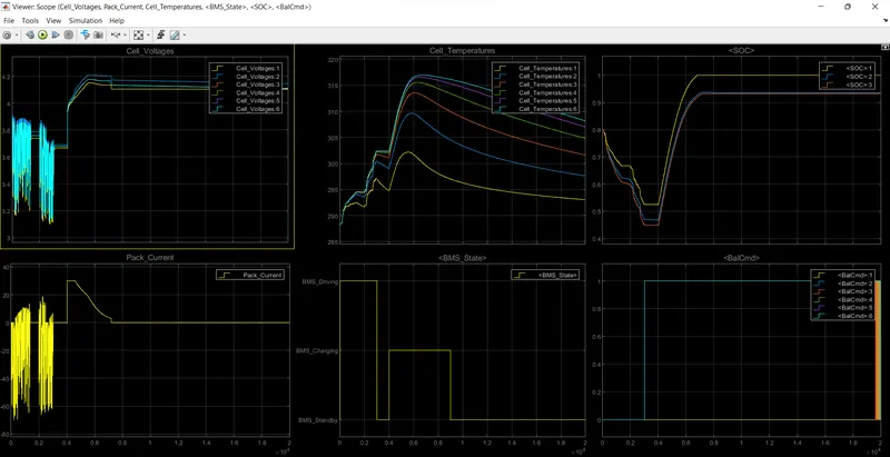
Driving (0 to 3000 sec); The vehicle is in the driving state, The SOC will decrease from 80% to 45%. Voltage is changed varying Between 3.9 to 3.1 V. Temperature of the cell is increased in charging and discharging mode. After driving, it goes to balance the state
Balancing (3000 to 4000 sec); for 1000 sec, The vehicle is in standby mode, and the Soc is in constant phase. The temperature of the cell is decreased in standby mode. After a balanced state, it goes to the charging state.
Charging (4000 to 9000 sec); for 5000 sec, The vehicle is in charging mode, Voltage reaches its maximum charged voltage, and SOC is increased from 45% to 100%. After the battery gets charged the temperature starts to fall.
Balancing (after 9000 sec); The vehicle is on standby mode.
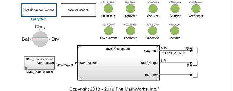
In a 2 test sequence:
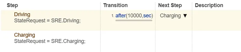
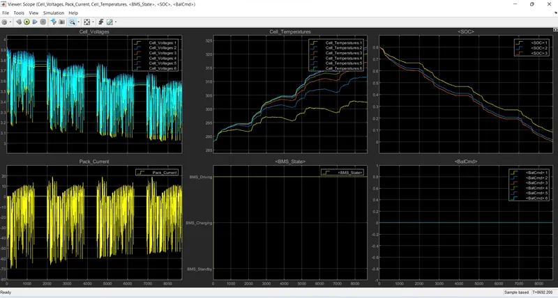
Driving (0 to 10000 sec); The vehicle is in a driving state, and the battery gets fully discharged at 8692 sec. so then the vehicle stop working and becomes standstill. The temperature keeps on rising till 8692 sec.
After 10000-sec charging operation won't take place.
All the dashboards lights are in green all are working without error.
Let's change the 2 test sequences; By changing the driving period to 8000 secs.
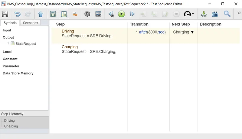
Driving (0 to 8000 sec); The vehicle is in a driving state, and the battery gets discharged till 8000 sec. SOC of the battery gets decreases to 5%. The temperature keeps on rising.
After 8000-sec charging operation take place at some instant, the battery temperature reaches its higher 323.15 kelvin i.e., 50 degrees Celsius. 8208 sec the battery temperature reaches its abnormal state and the charging soc is stopped.
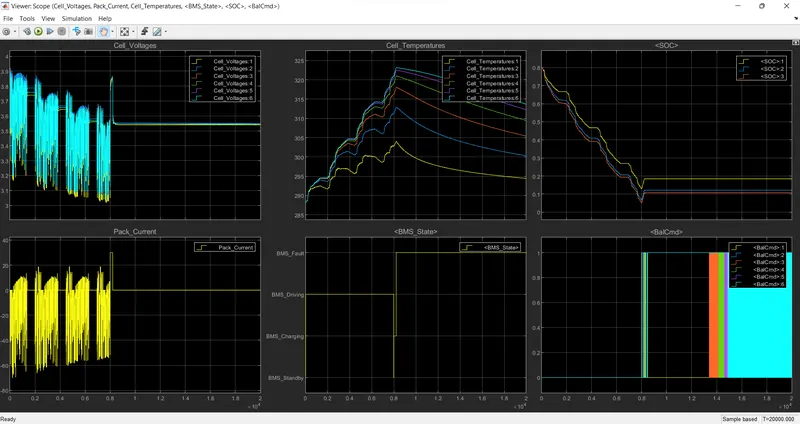
BMS state shows that BMS enters into a fault state at 8208 sec.
Bms state and temperature state shows red light which indicates the error (shown below figure)
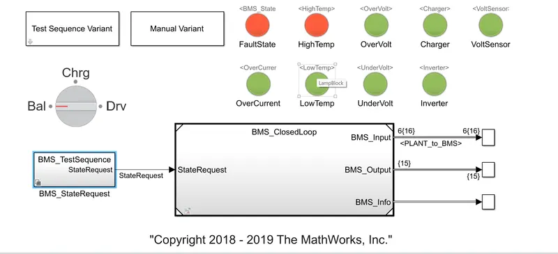
figure 3.
In 3 test sequences;
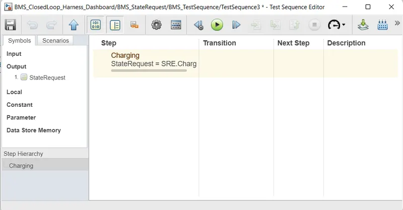
Charging 0 to 20000 sec; the vehicle is in charging mode and the battery gets charged up to 100% within 2000 secs. temperature raised up to 2000sec.
Soc is constant after 2000sec, temperature is falling, and Voltage get decreased.
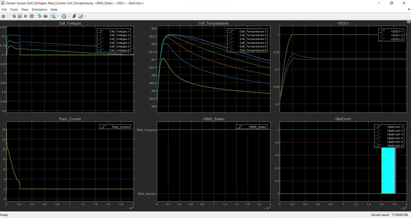
Dashboard all glows green.
2. What is coulomb counting? Refer to the above model and explain how BMS implements coulomb counting for SOC estimation.
SOC is the level of charge of a battery relative to its capacity. SOC 0(0%) is empty and 1(100%) is full.
It is the ratio of the charge stored in the battery at time instant 't' to the nominal capacity
Coulomb counting:
The coulomb counting method measures the charging and discharging current of the battery and integrates their values over time.
SOC equation for coulomb counting method
`SOC(t) = SOC(t-1)+ (i(t))/C_(bat) *Deltat`
where
- SOC(t) = Battery state of charge at time t
- SOC(t-1) = Battery initial state of charge (previous state)
- i(t) = Charge/ discharge current at time t. i(t) is positive for charging and negative for discharging.
- t = Time in an hour
- C_bat = Battery capacity in ampere-hour.
Few parameters are not taken into account (temperature, aging effect, discharge rate, etc) in the coulomb counting method.
Coulomb counting in the model
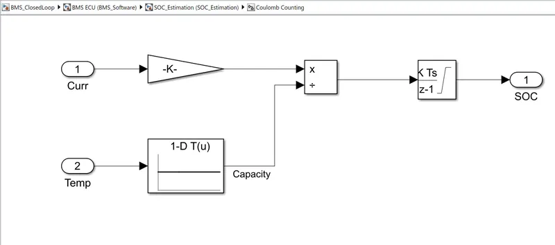
Current is divided by 3600 to convert sec to hr
Temp and its corresponding battery nominal capacity is given to the lookup table block. By dividing the current(ah) and battery capacity(ah) and integrating the coming result we get the SOC of the battery.
Related Matlab files are attached below for reference